John Deere 5083E and 5093E Tractors Diagnosis and Test Service Technical Manual (TM608919)
Catalog:
Model:
Complete Diagnosis & Tests Technical Manual with electrical wiring diagrams for John Deer 5083E and 5093E Tractors, with workshop information to maintain, diagnose, and rebuild like professional mechanics.
John Deer 5083E and 5093E Tractors workshop Diagnosis & Tests technical manual includes:
* Numbered table of contents easy to use so that you can find the information you need fast.
* Detailed sub-steps expand on repair procedure information
* Numbered instructions guide you through every repair procedure step by step.
* Troubleshooting and electrical service procedures are combined with detailed wiring diagrams for ease of use.
* Notes, cautions and warnings throughout each chapter pinpoint critical information.
* Bold figure number help you quickly match illustrations with instructions.
* Detailed illustrations, drawings and photos guide you through every procedure.
* Enlarged inset helps you identify and examine parts in detail.
TM608919 English - John Deer 5083E and 5093E Tractors Diagnostic Technical Manual (February 2015).pdf
TM608980 Turkish - 5083E ve 5093E Traktörler Arıza Tanı Teknik El Kitabı.pdf
PRODUCT DETAILS:
Total Pages: 1,203 pages
File Format: PDF (bookmarked, ToC, Searchable, Printable)
Category: Diagnosis and Tests
Language: English Turkish
Published on 2015/02/26
TABLE OF CONTENTS................1
Section 210: General................22
Group 05: Safety................22
Recognize Safety Information................26
Understand Signal Words................27
Follow Safety Instructions................28
Prepare for Emergencies................29
Wear Protective Clothing................30
Protect Against Noise................31
Handle Fuel Safely—Avoid Fires................32
Fire Prevention................33
In Case of Fire................34
Use Foldable ROPS and Seat Belt Properly................35
Stay Clear of Rotating Drivelines................36
Use Steps and Handholds Correctly................38
Read Operator Manuals for ISOBUS Implements................39
Use Seat Belt Properly................40
Vibration................41
Operating the Tractor Safely................42
Avoid Backover Accidents................44
Limited Use in Forestry Operation................45
Operating the Loader Tractor Safely................46
Keep Riders Off Machine................47
Passenger Seat................48
Use Safety Lights and Devices................49
Towing Trailers/Implements Safely (Mass)................50
Use Caution On Slopes and Uneven Terrain................51
Freeing a Mired Machine................52
Avoid Contact with Agricultural Chemicals................53
Handle Agricultural Chemicals Safely................54
Handling Batteries Safely................56
Avoid Heating Near Pressurized Fluid Lines................58
Remove Paint Before Welding or Heating................59
Handle Electronic Components and Brackets Safely................60
Practice Safe Maintenance................61
Avoid Hot Exhaust................62
Clean Exhaust Filter Safely................63
Work In Ventilated Area................66
Support Machine Properly................67
Prevent Machine Runaway................68
Park Machine Safely................69
Transport Tractor Safely................70
Service Cooling System Safely................71
Service Accumulator Systems Safely................72
Service Tires Safely................73
Service Front-Wheel Drive Tractor Safely................74
Tightening Wheel Retaining Bolts/Nuts................75
Avoid High-Pressure Fluids................76
Do Not Open High-Pressure Fuel System................77
Store Attachments Safely................78
Dispose of Waste Properly................79
Group 15: General References................23
General References - Summary of References................81
Metric Bolt and Screw Torque Values................82
Unified Inch Bolt and Screw Torque Values................84
Glossary of Terms................87
Hydraulic Circuit Symbols................91
Wiring Diagram and Schematic Information................92
Electrical Schematic Symbols................93
Reading Wiring Schematics and Diagrams................96
Visually Inspect Electrical System................100
Electrical Procedure................101
Using a Probe Light................105
Circuit Types................107
Circuit Malfunctions................109
Understanding Electrical vs. Electronic Circuits................112
Relay Circuit Types................115
Using a Digital Multimeter................128
Troubleshooting Unresolved Electrical/Electronic Problems................130
Section 211: Diagnostic Trouble Codes................131
Group CCU: CCU Code Diagnostics................131
CCU 000629.12 - CCU Control Unit Fault................131
CCU 001638.00 - Hydraulic Oil Temperature Very Hot................131
CCU 001638.03 - Hydraulic Oil Temperature Sensor Circuit Voltage High................131
CCU 001638.04 - Hydraulic Oil Temperature Sensor Circuit Voltage Low................131
CCU 001883.00 - Rear PTO Overspeed................131
CCU 001883.01 - Rear PTO Underspeed................131
CCU 524016.04 - CCU Switched Supply Voltage Low................131
CCU 524037.02 - MFWD Switch Circuit Fault................131
CCU 524224.14 - Rear PTO Disabled................131
CCU 524235.05 - MFWD Solenoid Circuit Fault................131
CCU 524252.05 - Rear PTO Solenoid Circuit Fault................131
CCU 600006.31 - Default DTC................131
Group PTR: PTR Code Diagnostics................131
PTR 000168.01 - PTR Unswitched Supply Voltage Low................131
PTR 000190.18 - Engine Speed Low................131
PTR 000191.00 - Transmission Overspeed During Calibration................131
PTR 000191.17 - Transmission Underspeed................131
PTR 000598.02 - Clutch Pedal Switch/Sensor Circuit Conflict................131
PTR 000598.04 - Clutch Pedal Switch/Transmission Enable Sensor Circuit Conflict................131
PTR 000628.02 - EOL Data Fault................131
PTR 000630.07 - PTR Calibration Fault/Tractor Movement................131
PTR 000630.14 - PTR Not Calibrated................131
PTR 000734.05 - Forward Solenoid Circuit Fault................131
PTR 000735.05 - Reverse Solenoid Circuit Fault................131
PTR 000752.03 - Infinitely Variable Shuttle Control Circuit Voltage High................131
PTR 000752.04 - Infinitely Variable Shuttle Control Circuit Voltage Low................131
PTR 001079.03 - Sensor Reference Circuit Voltage High................131
PTR 001079.04 - Sensor Reference Circuit Voltage Low................131
PTR 001504.30 - Seat Switch Circuit Fault................131
PTR 523959.31 - Operator Left Seat with Directional Reverser Lever in Gear................131
PTR 523960.31 - Operator Not Seated During a Directional Reverser Lever Command................131
PTR 524017.07 - Gearshift Lever in Park with Directional Reverser Lever in Gear................132
PTR 524020.31 - Directional Reverser Lever in Gear at Power-Up................132
PTR 524021.31 - Directional Reverser Lever Switch Circuit Fault................132
PTR 524029.02 - Clutch Pedal Sensor Circuit Conflict................132
PTR 524029.15 - Clutch Pedal Sensor Circuit Voltage High................132
PTR 524029.16 - Clutch Pedal Sensor Circuit Voltage High, Neutral Recoverable................132
PTR 524029.17 - Clutch Pedal Sensor Circuit Voltage Low................132
PTR 524029.18 - Clutch Pedal Sensor Circuit Voltage Low, Neutral Recoverable................132
PTR 524060.03 - Transmission Enable Signal High During Operation................132
PTR 524060.04 - Transmission Enable Signal Low During Operation................132
PTR 524081.31 - Come Home Detected................132
PTR 524160.02 - Not Neutral Signal Conflicts with Neutral Signal................132
PTR 524230.05 - Enable Proportional Valve Circuit Fault................132
PTR 524230.07 - Enable Valve Stuck Open................132
PTR 524234.03 - Enable Pressure Sensor Circuit Voltage High................132
PTR 524234.04 - Enable Pressure Sensor Circuit Voltage Low................132
Section 212: Observable Symptoms................237
Group 20: Engines................237
Engine Problems................237
Group 30: Fuel and Air................237
Fuel and Air Problems................237
Group 40: Electrical................237
Starting and Charging Problems................237
Lighting Problems................237
Instrument Cluster Problems................237
Miscellaneous Electrical Problems................237
Group 45: Control Units................237
Control Unit Problems................237
Group 50: Transmission................237
PowrReverser™ Problems................237
Group 56: Drive Systems................237
Differential Lock Problems................237
MFWD Problems................237
Rear Mechanical PTO Problems................237
Group 60: Steering and Brakes................237
Steering Problems................237
Brake Problems................237
Group 70: Hydraulics................237
SCV Problems................237
Hitch Problems................237
Hydraulic Problems................237
Group 90: Operator Station................237
HVAC Problems................237
Radio Problems................237
Seat Problems................237
Wiper Problems................237
Section 213: System Diagnosis................267
Group 40: Electrical................267
Starting System Diagnosis................267
Group 50: Transmission................267
PowrReverser™ Transmission System Diagnosis................267
Group 56: Drive Systems................267
Differential Lock System Diagnosis................267
MFWD System Diagnosis................267
Rear Mechanical PTO System Diagnosis................267
Group 60: Steering and Brakes................267
Steering System Diagnosis................267
Rear Brake System Diagnosis................267
Group 70: Hydraulics................267
Single and Dual Rear SCV System Diagnosis................267
Dual Mid-Mount SCV System Diagnosis................267
Rear Mechanical Hitch System Diagnosis................267
Hydraulics - Hydraulic Trailer Brake System Diagnosis................267
Group 90: Operator Station................267
HVAC System Diagnosis................267
Section 220: Engines................314
Group 05: General Information................314
Engine General Information - Summary of References................316
John Deere Engine Repair—Use Component Technical Manual................317
General Engine Specifications................318
Tractor-Specific Engine Information................319
Group 15: Tests and Adjustments................314
Engine Tests and Adjustments - Summary of References................321
Throttle Lever Adjustment................322
Group 20: Theory of Operation................314
Engine Theory of Operation - Summary of References................324
Overview of Tractor Engines................325
Section 230: Fuel and Air................326
Group 05: General Information................326
Fuel and Air General Information - Summary of References................328
John Deere Engine Fuel Systems Repair—Use Component Technical Manual................329
Group 20: Theory of Operation................326
Fuel and Air Theory of Operation - Summary of References................331
Fuel System Operation—Cab................332
Fuel System Operation—OOS................334
Air Intake System Operation................336
Section 240: Electrical System................338
Group 05: General Information................338
Electrical System General Information - Summary of References................343
Load Center Fuses and Relays................344
Group SE01: SE01—Starting and Charging, SE02—Fuel Supply System................338
SE01—Starting and Charging System, SE02— Fuel System - Summary of References................352
Key Switch, Starter, Alternator and Starting Aid Functional Schematic................353
PTO and Fuel Supply System Functional Schematic................355
Air Heater Circuit Test................356
Battery Inspection Test................358
Cold Advance Circuit Test................367
Charging System Circuit Test................369
Fuel Flow Circuit Test................372
Key Switch Circuit Test................375
Rear PTO Lever Position Switch Circuit Test................377
Starter Circuit Test................378
Group SE03: SE03—Accessory Power, SE04—Horn................338
SE03—Accessory Power, SE04—Horn - Summary of References................381
Accessory Power and Horn Functional Schematic................382
Accessory Power Circuit Test................383
Horn Circuit Test................386
Group SE07A: SE07A, SE08A—Cab Lighting................338
SE07A, SE08A—Cab Lighting - Summary of References................390
Cab Lighting Functional Schematic................391
Headlight Circuit Test (Cab)................394
Tail Light Circuit Test (Cab)................402
Light Switch Circuit Test (Cab)................409
Right Turn Signal Light Circuit Test (Cab)................411
Left Turn Signal Light Circuit Test (Cab)................417
Warning Light Circuit Test (Cab)................423
Front Work Light Circuit Test (Cab)................429
Rear Work Light Circuit Test (Cab)................434
Beacon Light Circuit Test (Cab)................439
License Plate Light Circuit Test (Cab)................442
Group SE07B: SE07B, SE07C, SE08B—OOS Lighting................339
SE07B, SE07C, SE08B—OOS Lighting - Summary of References................447
OOS Lighting Functional Schematic................448
Headlight Circuit Test (OOS)................451
Tail Light Circuit Test (OOS)................457
Tail Light Circuit Test (OOS) (with Warning Light Switch)................461
Light Switch Circuit Test (OOS)................465
Right Turn Signal Light Circuit Test (OOS)................467
Right Turn Signal Light Circuit Test (OOS) (with Warning Light Switch)................473
Left Turn Signal Light Circuit Test (OOS)................479
Left Turn Signal Light Circuit Test (OOS) (with Warning Light Switch)................485
Warning Light Circuit Test (OOS)................491
Warning Light Circuit Test (OOS) (with Warning Light Switch)................498
Front Work Light Circuit Test (OOS)................507
Rear Work Light Circuit Test (OOS)................510
Rear Work Light Circuit Test (OOS) (with Rear Work Light Switch)................513
Beacon Light Circuit Test (OOS)................517
License Plate Light Circuit Test (OOS)................520
Group SE09: SE09—Junction Block................339
SE09—Junction Block - Summary of References................524
Junction Block Functional Schematic................525
Junction Block Power Circuit Test................526
Group SE11: SE11—Trailer Connector................339
SE11—Trailer Connector - Summary of References................531
Trailer Connector Functional Schematic................532
Trailer Power Circuit Check................533
Group SE13: SE13—BackUp Alarm, SE15—Power Outlet (Cab Only)................339
SE13—BackUp Alarm, SE15—Power Outlet - Summary of References................537
Backup Alarm and Power Outlet Functional Schematic................538
Backup Alarm Circuit Test................540
Convenience Outlet Circuit Test................542
Power Outlet Circuit Test................545
Auxiliary Power Strip Circuit Test................547
Group SE16: SE16—Heating and Air Conditioning................340
SE16—Heating and Air Conditioning - Summary of References................551
Heating and Air Conditioning Functional Schematic................552
Heater and Blower Circuit Test................553
Air Conditioner Control and Compressor Circuit Test................561
Group SE20: SE20—Front Wiper System, SE21—Rear Wiper System................340
SE20—Front Wiper System, SE21—Rear Wiper System - Summary of References................566
Front and Rear Wiper/Washer Functional Schematic................567
Front Wiper/Washer Circuit Test................569
Rear Wiper/Washer Circuit Test................574
Group SE22: SE22—Dome Light, Door Switch, and Radio (Cab Only)................340
SE22—Dome Light, Door Switch, and Radio (Cab Only) - Summary of References................580
Dome Light, Door Switch, and Radio Functional Schematic................581
Dome Light Circuit Test................582
Right Hand Console Light Circuit Test................586
Radio/Clock Circuit Test................588
Radio Speaker Circuit Test................593
Radio Antenna Circuit Test................595
Group SE24: SE24—Instrument Cluster................340
SE24—Instrument Cluster - Summary of References................598
Instrument Cluster Functional Schematic................599
Instrument Cluster Test................600
Engine Oil Pressure Input Circuit Test................604
Air Filter Restriction Switch Circuit Test................606
Fuel Level Sensor Circuit Test................608
Engine Coolant Temperature Sensor Circuit Test................610
Left Turn Signal Indicator Input Circuit Test................613
Right Turn Signal Indicator Input Circuit Test................615
High Beam Headlight Input Circuit Test................617
Flasher (Turn Signal Light and Warning Light) Output Circuit Test................619
Battery Charge Indicator Input Circuit Test................621
PTO Switch Input Circuit Test................623
Seat Switch Input Circuit Test................625
Secondary Brake Switch Circuit Test................627
Group SE25: SE25—Seat Switch, SE26—ELX Relay and Fuses, SE28—Brake Switch................341
SE25—Seat Switch, SE26—ELX Relay and Fuses, SE28—Brake Switch - Summary of References................630
Seat Switch, ELX Relay and Fuses, and Brake Switch Functional Schematic................631
Brake Light Circuit Test................632
Seat Switch Circuit Test................634
Group SE29: SE29—Electrohydraulic Control (EHC) Unit, SE33—Service ADVISOR™................341
SE29—Electrohydraulic Control (EHC) Unit, SE33—Service ADVISOR™/Power - Summary of References................638
Electrohydraulic Control (EHC) Unit and Service ADVISOR™ Functional Schematic................639
Electrohydraulic Control (EHC) Unit (CCU and PTR) Test................640
Clutch Enable Proportional Valve Circuit Test................646
Clutch Pedal Position Sensor Circuit Test................650
Enable Pressure Sensor Circuit Test................655
Engine Speed Sensor Circuit Test................661
Forward Neutral Reverser (FNR) Switch Circuit Test................665
Park Switch Circuit Test................669
Power Shuttle Control Circuit Test................674
Topshaft Speed Sensor Circuit Test................679
Transmission Forward Solenoid Circuit Test................684
Transmission Reverse Solenoid Circuit Test................687
Hydraulic Oil Temperature Sensor Circuit Test................690
Section 245: Control Units................695
Group 05: General Information................695
Control Units General Information - Summary of References................700
Electro-Hydraulic Controller General Information................701
Access Control Unit Addresses................718
Performance Monitor General Operation................709
Diagnostic Trouble Code Listing................713
PRF Code List................714
CCU Code List................715
PTR Code List................716
Control Unit Addresses................718
Address 223-251 — General Control Unit Data................870
CCU Address List................720
PTR Address List................722
Programming Control Units................725
CAN Communication System Theory of Operation................732
VIN Security Fault Diagnosis................734
CAN Network Voltage Checks................735
Group CCU: CCU - Chassis Control Unit................695
Control Units CCU - Summary of References................741
Chassis Control Unit (CCU) Calibration................742
CCU 000 — Initial Address................751
CCU 001 — Recall Diagnostic Codes................752
CCU 002 — System Beep Address With Speed Sensors................753
CCU 003 — System Beep Address Without Speed Sensors................756
CCU 004 — Engine and Rear PTO Speed Sensor Status................758
CCU 005 — Wheel Speed Sensor Status................759
CCU 006 — Rear PTO Switch Status................760
CCU 007 — MFWD Switch Status................761
CCU 008 — Secondary Hand Brake, Left Brake, Right Brake Switch Status................762
CCU 009 — Sensor Supply Status................763
CCU 010 — Hydraulic Oil Temperature Sensor Voltage................764
CCU 030 — System Voltage................765
CCU 031 — Sensor Reference Voltage................766
CCU 032 — Engine Speed................767
CCU 033 — Rear PTO Speed................768
CCU 034 — Wheel Speed................769
CCU 036 — Hydraulic Oil Temperature................770
CCU 060 — MFWD Configuration................771
CCU 061 — Rear PTO Setup 1................772
CCU 062 — Rear PTO Setup 2................773
CCU 063 — Engine Pulses Per PTO Shaft Revolution Configuration................774
CCU 064 — Rear PTO Pulses Per PTO Shaft Revolution Configuration................775
CCU 065 — Wheel Speed Pulses Per Axle Revolution Configuration................776
CCU 066 — Rear Tire Rolling Circumference................777
CCU 069 — Diagnostic Code Purge Setting................779
CCU - Beep Mode Test With Speed Sensors................780
CCU - Beep Mode Test Without Speed Sensors................782
CCU - Controller Theory of Operation................783
CCU - Hydraulic Oil Temperature Sensor Theory of Operation................785
CCU - Engine Speed Sensor Theory of Operation................786
Group PTR: PTR - Power Train Reverser................696
Control Units PTR - Summary of References................788
Power Train Reverser (PTR) Control Unit Configuration and Calibration................789
PTR 000 — Initial Address................814
PTR 001 — Recall Diagnostic Codes................815
PTR 002 — PTR System Beep Mode................816
PTR 003 — PTR System Beep Mode With Speed Sensors................818
PTR 004 — Engine and Countershaft Speed Sensor Status................820
PTR 005 — Come Home, Trans Enable, Clutch Pedal Switch, and Seat Switch Status................822
PTR 006 — Forward, Neutral, Not Neutral, and Reverse Switch Status................824
PTR 007 — High/Low Switch Status................825
PTR 008 — Park Switch Status................826
PTR 009 — Seat Switch Status................827
PTR 010 — Clutch Disengaged Switch Status................828
PTR 011 — Power Shuttle Input Voltage................829
PTR 012 — Trans Enable Pressure Sensor Voltage................830
PTR 013 — Clutch Pedal Potentiometer Channel A Voltage................832
PTR 014 — Clutch Pedal Potentiometer Channel B Voltage................833
PTR 022 — Clutch Pack Overfill Protection Status................834
PTR 030 — PTR Switched Supply Voltage................835
PTR 031 — PTR Sensor Supply Voltage................836
PTR 032 — Clutch Pedal Position................837
PTR 033 — Clutch Pedal Pressure Command................838
PTR 034 — Trans Enable Actual Pressure................839
PTR 035 — Countershaft Pulses Per Revolution................841
PTR 036 — Countershaft Speed................842
PTR 037 — Hydraulic Oil Temperature................843
PTR 060 — Transmission Type................844
PTR 061 — Hydraulic Oil Type Selection................845
PTR 062 — Temperature Offset For Alternate Hydraulic Oil................846
PTR 063 — Transmission Calibration................847
PTR 064 — Transmission Fill Pressure and Fill Time Calibration Values................849
PTR 065 — Forward Valve Fill Pressure Adjustment................851
PTR 066 — Reverse Valve Fill Pressure Adjustment................852
PTR 067 — Forward Valve Fill Time Adjustment................853
PTR 068 — Reverse Valve Fill Time Adjustment................854
PTR 069 — PowerShuttle Setup Status................855
PTR 070 — PowerShuttle Minimum Wheel Speed Fill Pressure................856
PTR 071 — PowerShuttle Minimum Wheel Speed................857
PTR 072 — Forward and Reverse Current Shift Pressure................858
PTR 073 — Coefficient for V◦2 Shift Logic (Non-PowrShuttle)................859
PTR 074 — Starting Shift Pressure for V◦2 Shift Logic (Non-PowrShuttle)................860
PTR 075 — Maximum Shift Pressure for V◦2 Shift Logic (Non-PowrShuttle)................861
PTR 076 — Vehicle model number................862
PTR 080 — Forward and Reverse Valves Test Mode................863
PTR 081 — Enable Valve Test Mode................864
PTR 082 — Enable Pressure................865
PTR 083 — Hi/Lo Switch Setup................866
PTR 084 — Park Switch Polarity................867
PTR 085 — Seat Switch Polarity................868
PTR 100 — Come Home Mode Enable................869
Address 223-251 — General Control Unit Data................870
PTR - Control Unit Beep Mode Test With Speed Sensors................871
PTR - Control Unit Beep Mode Test Without Speed Sensors................875
PTR—Clutch Pedal Switch Circuit Test................876
PTR - Control Unit Theory of Operation................878
PTR - Directional Reverser Switch Theory of Operation................882
PTR - Clutch Disengaged Switch Theory of Operation................883
PTR - Optional Infinitely Variable Shuttle Control Theory of Operation................884
PTR - Park Switch Theory of Operation................885
PTR - Seat Switch Theory of Operation................886
PTR - Forward Solenoid Theory of Operation................887
PTR - Reverse Solenoid Theory of Operation................888
PTR - Clutch Enable Proportional Valve Theory of Operation................889
PTR - Clutch Pedal Position Sensor Theory of Operation................890
PTR - Enable Pressure Sensor Theory of Operation................891
PTR - Countershaft Speed Sensor Theory of Operation................892
Section 250: Transmission................893
Group 10: Preliminary and Operational Checks................893
Transmission Preliminary and Operational Checks - Summary of References................895
Transmission Preliminary Checks................896
Transmission Operational Checks................898
Group 15: Tests and Adjustments................893
Transmission Tests and Adjustments - Summary of References................902
Install Test Equipment—PowrReverser™................903
PowrReverser™ Control Valve Tests................909
PowrReverser™ Pump Flow Test................1038
PowrReverser™ Main Pressure Relief Valve Adjustment................917
Group 20: Theory of Operation................893
Transmission Theory of Operation - Summary of References................920
PowrReverser™ Transmission Hydraulic Schematic................921
Power Train Components................923
Mechanical PTO Clutch Components................924
Mechanical PTO Clutch Operation—Clutch Disengaged................925
Mechanical PTO Clutch Operation—Clutch Engaged................927
PowrReverser™ General Information................929
PowrReverser™ Clutch Components................930
PowrReverser™ Clutch Operation in Forward................931
PowrReverser™ Clutch Operation in Reverse................933
PowrReverser™ Control Valve Operation—Electro-Hydraulic Directional Reverser in Neutral................935
PowrReverser™ Control Valve Operation—Electro-Hydraulic Directional Reverser in Forward................937
PowrReverser™ Control Valve Operation—Electro-Hydraulic Directional Reverser in Reverse................939
Transmission Components................941
PowrReverser™ Transmission—Gearshift Power Flow................943
PowrReverser™ Transmission—Range Shift Power Flow................945
Gearshift Synchronizer Operation................947
PowrReverser™ Transmission Lubrication System................949
Section 256: Drive Systems................950
Group 10: Preliminary and Operational Checks................950
Drive Systems Preliminary and Operational Checks - Summary of References................952
Drive Systems Preliminary Checks................953
Rear Differential Lock Operational Check................955
PTO Operational Checks................956
MFWD Operational Checks................958
Group 15: Tests and Adjustments................950
Drive Systems Tests and Adjustments - Summary of References................961
Adjust PTO Clutch Lever Linkage................962
Park Brake Band Adjustment................964
Park Brake Linkage Adjustment................966
Group 20: Theory of Operation................950
Drive Systems Theory of Operation - Summary of References................969
Final Drive Components................970
Differential Power Flow................971
Differential Lock Operation................973
Final Drive Operation................975
Mechanical Front Wheel Drive (MFWD) Drop Gearbox Operation................976
Standard Mechanical PTO Components................978
Standard Mechanical PTO Operation................979
540/540E Mechanical PTO Components................981
540/540E Mechanical PTO Operation................982
Park Brake Components................984
Park Brake Operation................986
Section 260: Steering and Brakes................988
Group 10: Preliminary and Operational Checks................988
Steering and Brakes Preliminary and Operational Checks - Summary of References................990
Steering Preliminary Check................991
Steering Operational Check................992
Rear Brakes Preliminary Check................993
Rear Brakes Operational Check................994
Group 15: Tests and Adjustments................988
Steering and Brakes Tests and Adjustments - Summary of References................997
Install Test Equipment—Steering and Brakes................998
Steering Pump Flow Test................1038
Steering Valve Relief Test................1002
Steering Leak Test................1003
Bleed Rear Brakes................1005
Rear Brake Valve Leak Test................1006
Brake Pedal Adjustment................1007
Adjust Brake Retractors................1009
Group 20: Theory of Operation................988
Steering and Brakes Theory of Operation - Summary of References................1011
Steering Valve Operation—Neutral and Manual Turning................1012
Steering Valve Operation—Power Turning................1014
Brake System Operation................1016
Brake Valve Operation................1018
Section 270: Hydraulics................1022
Group 10: Preliminary and Operational Checks................1022
Hydraulics Preliminary and Operational Checks - Summary of References................1025
Hydraulic System Preliminary Checks................1026
Rear Hitch System Operational Check................1028
Hydraulics - Hydraulic Trailer Brake System Operational Check................1030
Group 15: Tests and Adjustments................1022
Hydraulics Tests and Adjustments - Summary of References................1032
Hydraulic Oil Warm-Up Procedure................1033
Install Test Equipment—Hydraulics................1034
Pump Flow Test................1038
Main Relief Valve Test................1040
Rockshaft Load Sense Relief Valve Test................1042
SCV Leakage Test................1044
Rockshaft Leakage Test................1046
Mid-Mount Control Valve Cable Adjustment................1048
Rockshaft Draft-Sensing and Position Control Cable Adjustment................1050
Rockshaft Lever Friction Adjustment................1051
Rockshaft Position-Sensing Feedback Linkage Adjustment................1052
Rockshaft Draft-Sensing Feedback Linkage Adjustment................1056
Hydraulics - Hydraulic Trailer Brake Valve Test................1058
Group 20: Theory of Operation................1022
Hydraulics Theory of Operation - Summary of References................1062
Hydraulic System Operation................1063
Hydraulic Filter Operation................1067
Hydraulic Pump Operation................1069
Rockshaft Control Valve Operation—Two Flow Regulator Valves................1071
Rockshaft Control Valve Operation—Neutral Position................1073
Rockshaft Control Valve Operation—Raise Position................1075
Rockshaft Control Valve Operation—Lower Position................1077
Surge Relief Valve Operation................1079
Rate-of-Drop Valve Operation—Full Open................1081
Rate-of-Drop Valve Operation—Full Closed................1082
Rockshaft Draft-Sensing Operation................1083
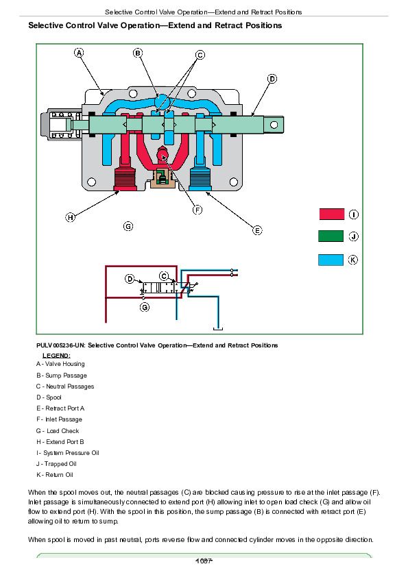
Selective Control Valve Operation—Neutral Position................1085
Selective Control Valve Operation—Extend and Retract Positions................1087
Selective Control Valve Operation—Boom Spool Float Position................1089
Dual Mid-Mount Control Valve Operation—Neutral Position................1091
Dual Mid-Mount Control Valve Operation—Extend and Retract Positions................1093
Dual Mid-Mount Control Valve Operation—Float Position................1095
Dual Mid-Mount Control Valve Operation—Regenerative Position................1097
Double-Acting Sleeve Coupler Operation................1099
Selective Control Valve Operation—Bucket Spool Regenerative Position................1101
Hydraulics - Hydraulic Trailer Brake Operation................1103
Section 290: Operator Station................1106
Group 10: Preliminary and Operational Checks................1106
Operator Station Preliminary and Operational Checks - Summary of References................1108
HVAC Preliminary Checks................1109
HVAC Operational Checks................1112
Group 15: Tests and Adjustments................1106
Operator Station Tests and Adjustments - Summary of References................1119
Install Test Equipment - A/C System................1120
A/C System Pressure Test................1121
A/C System Static Pressure Test................1129
Temperature Drop Test................1134
Group 20: Theory of Operation................1106
Operator Station Theory of Operation - Summary of References................1141
Refrigerant Circuit Layout................1142
Air Conditioning Refrigerant Circuit................1144
Air Conditioning Compressor Operation................1146
Air Conditioning Condenser Operation................1147
Air Conditioning Receiver/Dryer Operation................1148
Air Conditioning Expansion Valve Operation................1149
Air Conditioning Thermostat Switch Operation................1152
Air Conditioning Evaporator Operation................1153
Air Conditioning High/Low Pressure Switch Operation................1154
Air Conditioning ON/OFF Switch and Temperature Control Knob Operation................1155
Heater Temperature Control Knob Operation................1156
Heating and Ventilation Operation................1157
Section 299: Service Tools................1159
Group 05: Dealer Fabricated Tools................1159
Dealer Fabricated Tools - Summary of References................1162
DFRW126................1163
DFRW213 — Hydraulic Trailer Brake Test / Bleed Assembly................1165
Group 10: Service Tools and Kits................1159
Service Tools and Kits - Summary of References................1168
AR94522................1169
D01074AA................1170
FKM10002................1171
FKM10302................1172
FKM10303................1173
FKM10305................1174
JDG774................1175
JDG10466................1176
JT02051................1177
JT02063................1178
JT02153................1179
JT02178................1180
JT03044................1181
JT03051................1182
JT03059................1183
JT03110................1184
JT03262................1185
JT03345................1186
JT03364................1187
JT03367................1188
JT03368................1189
JT03481................1190
JT03481-1................1191
JT03481-3................1192
JT03481-4................1193
JT03520................1194
JT05469................1195
JT05473................1196
JT05494................1197
JT05498................1198
JT05634................1199
JT05685................1200
JT05791................1201
JT05843................1202
JT07032................1203
JT07041................1204
JT07148................1205
John Deer 5083E and 5093E Tractors Diagnosis and Test Service Technical Manual (TM608919)


