TM1717 - Diagnostics and Repair Technical Manual for John Deere Tractors Models 5310N and 5510N
Catalog:
Model:
Complete All Inclusive Technical Manual with electrical wiring diagrams for John Deere 5310N, 5510N Tractors (North America), with all the technical information to maintain, diagnostic, repair, rebuild like professional mechanics (Diagnosis, Operation, Tests, Repair, Service, Troubleshooting).
John Deere Tractors 5310N, 5510N workshop technical service manual includes:
* Numbered table of contents easy to use so that you can find the information you need fast.
* Detailed sub-steps expand on repair procedure information
* Numbered instructions guide you through every repair procedure step by step.
* Troubleshooting and electrical service procedures are combined with detailed wiring diagrams for ease of use.
* Notes, cautions and warnings throughout each chapter pinpoint critical information.
* Bold figure number help you quickly match illustrations with instructions.
* Detailed illustrations, drawings and photos guide you through every procedure.
* Enlarged inset helps you identify and examine parts in detail.
TM1717 English - John Deere 5310N and 5510N Tractors Diagnostic and Repair Technical Manual .pdf
PRODUCT DETAILS:
Total Pages: 1,502 pages
File Format: PDF (PC/Mac/Android/Kindle/iPhone/iPad; bookmarked, ToC, Searchable, Printable)
Language: English
MAIN SECTIONS
Foreword
General Information
Safety
General Specifications
Fuel and Lubricants
Serial Number Locations
Features and Accessories
Engine Repair
Engine
Cooling System
Fuel and Air Repair
Fuel System
Air Intake System
Speed Control Linkage
Electrical Repair
Battery, Starter, and Alternator
Electrical System Components
Wiring Harness
Power Train Repair
Clutch Housing
Clutch Assembly
Synchronized Reverser
Transmission
Rear PTO Drive Shaft
Differential
Final Drives
Mechanical Front Wheel Drive
Creeper Assembly
Steering and Brake Repair
Steering Repair
Brake Repair
Hydraulic Repair
Hydraulic Pump and Filter
Hydraulic Oil Cooler
Rockshaft
Selective Control Valve (SCV)
Hydraulic Power Beyond
Miscellaneous Repair
Front Axle-2WD
Wheels
Fenders
3-Point Hitch
Operator Station Repair
Seat and Support
ROLL-GARD™
Rear Bar
Cab Components
Air Conditioning System
Heating System
Operational Checkout Procedures
Operational Checkout Procedures
Engine Operation, Tests and Adjustments
Component Location
Theory of Operation
Diagnosis, Tests and Adjustments
Fuel and Air Operation, Tests and Adjustments
Component Location
Theory of Operation
Diagnosis, Tests and Adjustments
Electrical System Operation, Tests & Adjust
Component Location
Theory of Operation
Diagnosis, Test and Adjustments
Wiring Schematics
Power Train Operation, Tests & Adjustments
Component Location
Theory of Operation
Diagnosis, Tests and Adjustments
Steering and Brake Operation, Test & Adjust
Component Location
Theory of Operation
Diagnosis, Tests and Adjustments
Hydraulic System Operation, Tests, and Adjustments
Component Location
Theory of Operation
Diagnosis
Hydraulic Tests
Adjustments
Hydraulic Schematics
Operator Station
Component Location
Theory of Operation
Diagnosis, Tests, and Adjustments
Dealer Fabricated Tools
TABLE OF CONTENTS
Section 10: General Information................27
Group 05: Safety................27
Recognize Safety Information................30
Understand Signal Words................31
Follow Safety Instructions................32
Handle Fluids Safely-Avoid Fires................33
Prevent Battery Explosions................34
Prepare for Emergencies................35
Prevent Acid Burns................36
Service Cooling System Safely................38
Handle Chemical Products Safely................39
Avoid High-Pressure Fluids................40
Park Machine Safely................41
Support Machine Properly................42
Wear Protective Clothing................43
Work in Clean Area................44
Service Machines Safely................45
Work in Ventilated Area................46
Illuminate Work Area Safely................47
Replace Safety Signs................48
Use Proper Lifting Equipment................49
Keep ROPS Installed Properly................50
Service Tires Safely................51
Avoid Harmful Asbestos Dust................52
Avoid Heating Near Pressurized Fluid Lines................53
Remove Paint Before Welding or Heating................54
Use Proper Tools................55
Dispose of Waste Properly................56
Live With Safety................57
Group 10: General Specifications................782
Machine Specifications................782
Service Recommendations for O-Ring Boss Fittings................72
Service Recommendations for Flat Face O-Ring Seal Fittings................74
Metric Cap Screw Torque Values-Grade 7................76
Metric Bolt and Cap Screw Torque Values................77
Unified Inch Bolt and Cap Screw Torque Values................79
Group 20: Fuel and Lubricants................28
Diesel Fuel Specifications................782
Storing Fuel................85
Do Not Use Galvanized Containers................86
Fill Fuel Tank................87
Diesel Engine Oil................89
Diesel Engine Coolant................90
Liquid Coolant Conditioner................91
Transmission and Hydraulic Oil................92
MFWD Gear Oil................93
Grease................94
Alternative and Synthetic Lubricants................95
Lubricant Storage................96
Group 25: Serial Number Locations................28
Serial Numbers................98
Product Identification Number Location................99
Engine Serial Number Location................100
Fuel Injection Pump Serial Number Location................101
Alternator Serial Number Location................102
Power Steering Valve Serial Number Location................103
Starter Serial Number Location................104
Transmission Serial Number Location................105
Front Axle (2WD) Serial Number Location................106
Mechanical Front Wheel Drive (MFWD) Serial Number Location................107
Air Conditioning Compressor Serial Number Location................108
Group 30: Features and Accessories................110
Features and Accessories................110
Standard Features................111
Factory Installed Optional Equipment................114
Field Installed Optional Kits and Accessories................115
Section 20: Engine Repair................116
Group 05: Engine................116
John Deere Engine Repair-Use CTM104, CTM125, and CTM207................118
Specifications................782
Service Equipment and Tools................785
Remove Engine-Tractors Without Cab................121
Install Engine-Tractors Without Cab................128
Remove Engine-Tractors With Cab................135
Install Engine-Tractors With Cab................146
Group 10: Cooling System................116
Engine Water Pump Repair-Use CTM104 or CTM125................157
Specifications................782
Remove and Inspect Radiator................159
Install Radiator................163
Replace Thermostat................167
Inspect and Replace Belt Tensioner................170
Section 30: Fuel and Air Repair................173
Group 05: Fuel System................173
Injection Pump, Nozzle and Governor Repair-Use CTM104 and CTM207 or CTM125................175
Specifications................782
Remove, Inspect, and Install Fuel Tank-Tractors Without Cab................177
Remove, Inspect, and Install Fuel Tank-Tractors With Cab................181
Replace Fuel Filter................185
Remove and Install Fuel Filter/Primer Pump Assembly................186
Group 10: Air Intake System................173
Turbocharger Repair-Use CTM104 or CTM125................188
Specifications................782
Remove, Inspect, and Install Air Cleaner Elements-5310N................190
Remove, Inspect, and Install Air Cleaner Elements-5510N................193
Remove Turbocharger-5310N................196
Install Turbocharger-5310N................198
Remove Turbocharger-5510N................200
Install Turbocharger-5510N................202
Turbocharger Break-In................204
Group 15: Speed Control Linkage................173
Inspect and Repair Speed Control Linkage................207
Section 40: Electrical Repair................209
Group 05: Battery, Starter, and Alternator................209
Starter Repair-Use CTM77................212
Remove and Install Battery-Tractor Without Cab................213
Remove and Install Battery-Tractor With Cab................215
Remove and Install Starter-5310N................217
Remove and Install Starter-5510N................219
Replace Alternator/Regulator-40 Amp Without Cab................222
Replace Alternator/Regulator-60 and 65 Amp With Cab................223
Group 10: Electrical System Components................209
Specifications................782
Service Equipment and Tools................785
Other Material................749
Replace Air Filter Restriction Switch-5310N................229
Replace Air Filter Restriction Switch-5510N................230
Replace Coolant Temperature Sender-5310N................231
Replace Coolant Temperature Sender-5510N................232
Replace Engine Speed Sensor................233
Replace Engine Oil Pressure Switch................234
Replace Manifold Heater................235
Replace Manifold Heater Relay................236
Replace Key Switch................238
Replace Light Switch................240
Replace Turn Signal Controller................242
Replace Instrument Panel................243
Replace Rear PTO Switch................247
Replace PTO Seat Switch................248
Replace Neutral Start Switch................249
Replace Fuel Level Sender-Tractors Without Cab................250
Replace Fuel Level Sender-Tractors With Cab................251
Replace Park Brake Switch................253
Replace Radio (Optional Equipment)................254
Replace Speakers (Optional Equipment)................256
Replace Antenna (Optional Equipment)................257
Replace Blower Control Switch................259
Replace Air Conditioning Temperature Control Switch................261
Replace Front Wiper/Washer Control Switch................265
Replace Dome Light................267
Replace Dome Light Switch................269
Replace Convenience Outlet................271
Replace Cab Plug-In Relays................1008
Replace Front Wiper Motor................274
Group 15: Wiring Harness................210
Special or Essential Tools................783
Service Parts Kits................786
Remove Connector Body-Blade Terminals................284
Replace WEATHER PACK WEATHER PACK is a trademark of Packard Electric. Connector................210
Install WEATHER PACK WEATHER PACK is a trademark of Packard Electric. Contact................210
Replace Front Wiring Harness-3-Cylinder................289
Replace Front Wiring Harness-4-Cylinder................291
Replace Rear Wiring Harness-Tractors Without Cab................293
Replace Rear Wiring Harness-Tractors With Cab................295
Replace Cab Wiring Harness-Lights................298
Replace Cab Wiring Harness-Main................300
Replace Cab Control Wiring Harness................302
Section 50: Power Train Repair................304
Group 05: Clutch Housing................304
Service Equipment and Tools................785
Other Material................749
Specifications................782
Separate Engine from Clutch Housing-Tractors Without Cab................312
Install Engine to Clutch Housing-Tractors Without Cab................318
Separate Engine from Clutch Housing-Tractors With Cab................324
Install Engine to Clutch Housing-Tractors With Cab................332
Inspect and Repair Clutch Pedal and Linkage................339
Group 10: Clutch Assembly................304
Essential Tools................783
Service Equipment and Tools................785
Other Material................749
Service Parts Kits................786
Specifications................782
Remove and Install Clutch Assembly................347
Disassemble and Inspect Clutch Assembly................348
Assemble Clutch Assembly................352
Traction Clutch Finger Adjustment................357
PTO Clutch Finger Adjustment................359
Remove and Inspect Clutch Release Mechanism and Shafts................361
Install Clutch Release Mechanism and Shafts................365
Group 15: Synchronized Reverser................304
Service Equipment and Tools................785
Specifications................782
Inspect and Repair F-N-R Selector Lever and Linkage................371
Inspect and Repair Synchronized Reverser................373
Group 20: Transmission................304
Service Equipment and Tools................785
Other Material................749
Specifications................782
Inspect and Repair Park Brake Lever................385
Separate Clutch Housing from Transmission................387
Install Clutch Housing to Transmission................394
Remove, Inspect, and Repair Gear Shift Lever................400
Remove, Inspect, and Repair Range Shift Lever................403
Remove Transmission................406
Disassemble and Inspect Transmission................412
Assemble and Install Transmission................416
Disassemble, Inspect and Assemble Shift Shaft Assemblies................425
Disassemble, Inspect, and Assemble Transmission Top Shaft................427
Disassemble, Inspect, and Assemble Range Reduction Shaft................430
Disassemble, Inspect, and Assemble Driven Shaft................432
Remove, Inspect, and Install MFWD and Range Gears................434
Remove, Inspect, and Repair Park Brake................436
Group 25: Rear PTO Drive Shaft................305
Service Equipment and Tools................785
Other Material................749
Specifications................782
Inspect and Repair Rear PTO Lever and Linkage................442
Inspect and Repair PTO Lever and Linkage (540/540E)................444
Remove and Install Rear PTO Drive Shaft Assembly................446
Disassemble, Inspect and Assemble Rear PTO Drive Shaft Assembly................448
Group 30: Differential................305
Essential Tools................783
Service Equipment and Tools................785
Other Material................749
Service Parts Kit................456
Specifications................782
Remove and Install Differential Assembly................458
Disassemble, Inspect, and Assemble Differential Assembly................460
Remove and Inspect Differential Drive Shaft................462
Install Differential Drive Shaft................466
Differential Cone Point Adjustment................470
Differential Backlash Adjustment................472
Remove, Inspect, and Install Differential Lock Assembly................474
Group 35: Final Drives................306
Essential Tools................783
Service Equipment and Tools................785
Other Material................749
Specifications................782
Remove and Install Final Drive Assembly................481
Remove and Inspect Planetary Drive Assembly................483
Install Planetary Drive Assembly................486
Remove, Inspect, and Install Axle Shaft Assembly................489
Group 40: Mechanical Front Wheel Drive................306
Essential Tools................783
Service Equipment and Tools................785
Other Material................749
Specifications................782
Inspect and Repair MFWD Lever and Linkage................497
Remove and Install MFWD Drop Gearbox................499
Disassemble and Inspect MFWD Drop Gearbox................501
MFWD Drop Gearbox Cross Section................504
Assemble MFWD Drop Gearbox................506
Remove, Inspect, and Install MFWD Drive Shaft................511
Remove and Install MFWD Axle................513
Remove and Install MFWD Axle Pivot Pin and Pivot Bushings................516
Disassemble and Inspect MFWD Outer Drive................518
Assemble MFWD Outer Drive................521
Remove, Inspect, and Install MFWD Swivel Housing................524
Remove, Inspect, and Install MFWD Axle Shaft................528
Remove and Install MFWD Differential Carrier Assembly................530
Disassemble and Inspect MFWD Differential Carrier Assembly................532
Assemble MFWD Differential Carrier Assembly................537
Group 45: Creeper Assembly................306
Other Material................749
Specifications................782
Remove and Install Creeper Assembly................549
Disassemble, Inspect, and Assemble Creeper Assembly................551
Section 60: Steering and Brake Repair................553
Group 05: Steering Repair................553
Specifications................782
Other Material................749
Service Parts Kits................786
Remove and Install Steering Column and Valve................558
Disassemble and Inspect Steering Valve................560
Assemble Steering Valve................564
Remove and Install Steering Cylinder-2WD Axle................569
Disassemble, Inspect and Assemble Steering Cylinder-2WD Axle................571
Disassemble, Inspect and Assemble Steering Cylinder-MFWD Axle................573
Remove, Inspect and Install Tie Rod Assembly-2WD Axle................576
Remove, Inspect and Install Tie Rod Assembly-MFWD Axle................578
Inspect and Replace Steering Hydraulic Lines-Without Oil Cooler................580
Inspect and Replace Steering Hydraulic Lines-With Oil Cooler................582
Group 10: Brake Repair................553
Specifications................782
Service Equipment and Tools................785
Other Material................749
Remove and Install Brake Valve................589
Disassemble and Inspect Brake Pedals................591
Brake Valve Cross Section................594
Assemble Brake Valve................596
Remove and Inspect Brakes................599
Install Brakes................602
Inspect and Replace Brake Hydraulic Lines................605
Section 70: Hydraulic Repair................607
Group 05: Hydraulic Pump and Filter................607
Specifications................782
Service Equipment and Tools................785
Service Parts Kits................786
Remove, Inspect, and Install Hydraulic Oil Pick-Up Screen................613
Remove and Install Hydraulic Pump-5310N................615
Remove Hydraulic Pump External Components-5310N................617
Disassemble and Inspect Hydraulic Pump-5310N................619
Assemble Hydraulic Pump-5310N................622
Install Hydraulic Pump External Components-5310N................624
Remove and Install Hydraulic Pump-5510N................626
Remove Large Capacity Hydraulic Pump External Components-5510N................628
Disassemble and Inspect Large Capacity Hydraulic Pump-5510N................630
Assemble Large Capacity Hydraulic Pump-5510N................633
Install Large Capacity Hydraulic Pump External Components-5510N................635
Remove and Install Hydraulic Oil Filter/Manifold................637
Inspect and Replace Hydraulic Supply/Return Lines................639
Group 06: Hydraulic Oil Cooler................607
Remove, Inspect, and Install Hydraulic Oil Cooler................643
Group 10: Rockshaft................607
Specifications................782
Service Equipment and Tools................785
Other Material................749
Service Parts Kits................786
Inspect and Repair Rockshaft Control Lever Assembly................650
Inspect and Repair Rockshaft Control Linkage................656
Inspect and Repair Draft Sensing Support Assembly................660
Remove, Inspect, and Install Secondary Relief Valve................662
Replace Rockshaft Surge Relief Valve................664
Remove, Inspect, and Install Rate-of-Drop Valve................665
Replace Rockshaft Control Valve................667
Replace Rockshaft End Cover................670
Remove and Install Rockshaft Case................674
Remove, Inspect, and Install Rockshaft Lift Arms................677
Remove, Inspect, and Install Rockshaft Piston and Cylinder................679
Group 15: Selective Control Valve (SCV)................608
Specifications................782
Other Material................749
Service Parts Kits................786
Remove and Install Selective Control Valve (SCV)................685
Disassemble, Inspect, and Assemble Selective Control Valve (SCV)................687
Group 20: Hydraulic Power Beyond................608
Inspect and Replace Power Beyond Lines and Fittings................694
Inspect and Replace Power Beyond Motor Control Lines and Fittings................696
Section 80: Miscellaneous Repair................697
Group 05: Front Axle-2WD................697
Specifications................782
Service Equipment and Tools................785
Remove and Install Front Axle-2WD................701
Inspect and Replace Pivot Pin and Bushings-2WD Axle................704
Remove and Install Spindle Assembly-2WD Axle................705
Inspect and Replace Spindle Shaft Bushings-2WD Axle................707
Group 10: Wheels................697
Specifications................782
Service Equipment and Tools................785
Inspect and Replace Front Wheel Bearings-2WD Axle................711
Group 15: Fenders................697
Specifications................782
Remove and Install Fenders................715
Group 20: 3-Point Hitch................697
Specifications................782
Inspect and Repair Draft Links................721
Inspect and Repair Adjustable Lift Links................722
Inspect and Repair Center Link................724
Remove and Install Drawbar and Support................726
Section 90: Operator Station Repair................728
Group 05: Seat and Support................728
Specifications................782
Remove and Install Seat and Support-Without Cab................732
Remove and Install Seat and Support-With Cab................733
Group 10: ROLL-GARDROLL-GARD is a trademark of Deere & Company.................728
Specifications................782
Remove and Install ROLL-GARD ROLL-GARD is a trademark of Deere & Company.................728
Group 15: Rear Bar................728
Specifications................782
Remove and Install Rear Bar-Without Cab................740
Remove and Install Rear Bar-With Cab................744
Group 20: Cab Components................728
Specifications................782
Other Material................749
Essential Tools................783
Remove Cab and Floor Plates................751
Install Cab and Floor Plates................759
Remove and Install Cab Outer Roof................765
Remove and Install Lower Front Window and Support................766
Remove and Install Rear Side Cab Windows................771
Remove and Install Rear Cab Window................773
Remove and Install Front Windshield................775
Remove and Install Cab Doors................777
Remove, Inspect, and Install Cab Recirculating/Fresh Air Filter................778
Group 25: Air Conditioning System................728
Specifications................782
Essential Tools................783
Service Equipment and Tools................785
Service Parts Kits................786
Hose and Tubing O-Ring Connection Torques................787
Recover/Recycle Air Conditioning Refrigerant................788
Replace Air Conditioning Receiver-Dryer................1441
Remove, Inspect, and Install Air Conditioning Condenser................1440
Remove, Inspect, and Install Air Conditioning Compressor................1439
Test Volumetric Efficiency of Compressor................1439
Test Compressor Shaft Seal Leakage................800
Disassemble and Assemble Compressor Clutch................802
Disassemble, Inspect, and Assemble Compressor................1439
Check Compressor Clutch Hub Clearance................807
Inspect Compressor Manifold................808
Remove and Install Compressor Relief Valve................809
Remove Evaporator/Heater Core Housing................810
Install Evaporator/Heater Core Housing................817
Remove and Install Blower Motors................822
Remove Evaporator/Heater Core................825
Leak Test Evaporator/Heater Core................829
Install Evaporator/Heater Core................830
Service Expansion Valve................1442
Expansion Valve Bench Test................833
Refrigerant Oil Information................835
Check Compressor Oil Charge................836
Determine Correct Refrigerant Oil Charge................837
Add Refrigerant Oil To System................839
System Information................840
Flush Air Conditioning System................841
Evacuate Air Conditioning System................844
Charge Air Conditioning System................846
Group 30: Heating System................729
Remove Heater Control Valve................850
Leak Test Heater Control Valve................852
Install Heater Control Valve................853
Section 210: Operational Checkout Procedures................855
Group 10: Operational Checkout Procedures................855
Operational Checkout Procedure Information................858
Engine Oil Level and Condition Check................859
Coolant Level and Condition Check................860
Transmission and Hydraulic Oil Check................861
Fan and V-Belt Check................862
Fan and Serpentine Belt Check................863
Compressor Belt Check................864
Fuel System Check................866
Air Intake System Check................867
Electrical System Check................869
Hydraulic System Check................870
MFWD Oil Check................871
MFWD Differential Oil Check................872
Indicator Lamps Check................873
Cab Blower Motor Check................874
A/C Compressor Clutch Check................883
Engine Start Check................876
Transmission Neutral Start Check................877
PTO Neutral Start Check................878
Engine Fast and Slow Idle Operation................879
Power Steering Check................880
Differential Lock Check................881
PTO Engagement Check................882
Clutch Check................883
Transmission Shift Check................884
Range Lever Shift Check................885
MFWD Drive Check................886
Park Brake Check................887
Rockshaft Check................888
Selective Control Valve Check................890
A/C Operational Check................892
Cab Heater Valve Check................893
Miscellaneous Checks................894
Section 220: Engine Operation, Tests and Adjustments................895
Group 05: Component Location................895
Component Location Information................1337
Engine External Components-Left Side................899
Engine External Components-Right Side................901
4-Cylinder Engine External Components-Left Side................899
4-Cylinder Engine External Components-Right Side................901
Group 10: Theory of Operation................895
Theory of Operation Information................1345
Engine Lubrication System Operation................909
Engine Cooling System Operation-3-Cylinder................913
Engine Cooling System Operation-4-Cylinder................915
Group 15: Diagnosis, Tests and Adjustments................1474
Diagnostic Information................1382
Engine Turns Over But Will Not Start or Starts Hard................919
Engine Runs Irregularly or Stalls Frequently................920
Engine Runs Rough................921
Engine Low Power................922
Engine Smokes-Black or Grey................924
Engine Smokes Excessively-White................925
Engine Uses Excess Fuel................926
Engine Has Excess Noise or Vibration................927
Engine Uses Excess Oil or Smokes Blue................928
Engine Has Low Oil Pressure................929
Engine Coolant Operating Temperature Incorrect................930
Oil In Coolant or Coolant in Oil................932
Radiator Bubble Test................933
Cooling System Test................935
Radiator Cap Pressure Test................936
Engine Oil Pressure Test................937
Cylinder Compression Pressure Test................939
Fuel Shut-Off Solenoid Check................941
Throttle Lever Adjustment................942
Slow Idle Adjustment................943
Fast Idle Adjustment................945
Injection Pump Timing Adjustment................947
Check and Adjust Valve Clearance................949
Fan/Alternator Drive Belt Adjustment-3-Cylinder without Cab................953
Compressor Drive Belt Adjustment-3-Cylinder with Cab................955
Turbocharger Boost Pressure Test................957
Bleed Fuel System................959
Section 230: Fuel and Air Operation, Tests and Adjustments................962
Group 05: Component Location................962
Component Location Information................1337
Fuel System Components................965
Air Intake System Components................967
Group 10: Theory of Operation................962
Theory of Operation Information................1345
Fuel System Operation................971
Fuel Filter and Priming Pump Operation................973
Fuel Injection Nozzle Operation................975
Air Intake System Operation................977
Turbocharger Operation................979
Group 15: Diagnosis, Tests and Adjustments................1474
Diagnostic Information................1382
Fuel and Air Diagnosis, Tests and Adjustments................1474
Section 240: Electrical System Operation, Tests Section 240: Electrical System Operation, Tests & Adjust{pgNO}984 Adjust................984
Group 05: Component Location................984
Component Location Information................1337
Engine Electrical Components................989
Dash Electrical Components................990
3-Cylinder Tractor Electrical Components-Without Cab................984
4-Cylinder Tractor Electrical Components-Without Cab................984
Tractor Electrical Components-With Cab................996
Cab Control Panel and Electrical Components................998
Group 10: Theory of Operation................984
Theory of Operation Information................1345
Fuse Block and Fuses-Tractors Without Cab................1002
Fuse Block and Fuses-Cab Tractors................1004
Cab Fuse Block and Fuses................1006
Relays................1008
Starting System Operation-Normal................1009
Starting System Operation-Bypass Attempt................1012
Manifold Heater System Operation................1014
Charging System Operation................1016
Lighting System Operation-Turn Signals................1018
Lighting System Operation-Warning Lights and Tail Light................1020
Lighting System Operation-Headlights and Instrument Lights................1022
Rear Field Light Operation-Tractors Without Cab................1024
Instrument Panel System Operation-Tachometer/Hour Meter................1026
Instrument Panel System Operation-Fuel Gauge................1028
Instrument Panel System Operation-Temperature Gauge................1030
PTO Warning System Operation................1032
Air Filter Restriction Indicator Operation................1034
Optional Horn Operation................1036
Accessory Relay and Optional Trailer Connection Operation................1037
Flood Light Operation-Tractors With Cab................1039
Blower Motor Operation-Tractors With Cab................1041
A/C Compressor Operation-Cab Tractors................1044
Front Wiper/Washer Operation-Cab Tractors................1047
Rear Wiper/Washer Operation-Cab Tractors................1049
Dome Light Operation-Cab Tractors................1051
Group 15: Diagnosis, Test and Adjustments................985
Diagnostic Information................1382
Wire Color Chart................1055
Starting System Test Points-Normal Operation................1057
Starting System Test Points-Bypass Attempt................1061
Manifold Heater Test Points................1064
Charging System Test Points................1067
Lighting System Test Points-Left Turn Signals (Tractors Without Cab)................1070
Lighting System Test Points-Right Turn Signals (Tractors Without Cab)................1074
Lighting System Test Points-Left Turn Signals (Tractors With Cab)................1078
Lighting System Test Points-Right Turn Signals (Tractors With Cab)................1082
Lighting System Test Points-Warning Lights (All Tractors)................1086
Lighting System Test Points-Rear Field Light (Tractors Without Cab)................1089
Lighting System Test Points-Flood Lights (Tractors With Cab)................1092
Lighting System Test Points-Dome Light (Tractors With Cab)................1096
Lighting System Test Points-Tail Light................1099
Lighting System Test Points-Headlights and Instrument Lights................1102
Instrument Panel System Test Points-Hourmeter and Tachometer................1106
Instrument Panel System Test Points-Fuel Gauge................1109
Instrument Panel System Test Points-Temperature Gauge................1112
Instrument Panel System Test Points-Oil Pressure................1115
PTO Warning System Test Points................1118
Air Filter Restriction Test Points................1121
Optional Horn Test Points................1124
Accessory Relay and Trailer Connector Test Points................1126
Blower Motor Test Points (Tractors With Cab)................1129
A/C Compressor Clutch Coil Test Points (Tractors With Cab)................1133
Front Wiper/Washer Test Points (Tractors With Cab)................1135
Battery Voltage and Specific Gravity Tests................1138
Charge Battery................1140
Battery Load Test................1142
Starter Amp Draw/RPM Test................1144
Starter No-Load Amp Draw/RPM Test................1146
Alternator/Regulator Test................1148
Starter Solenoid Test................1150
Starter Relay Test................1151
Key Switch Test................1153
Plug-In Relay Test................1155
Diode Pack Test................1157
Fuse Test................1159
Neutral Start Switch Test................1160
PTO Switch Test................1161
PTO Seat Switch Test................1163
Light Switch Test................1164
Turn Signal Controller Test................1166
Fuel Shut-Off Solenoid Test................1167
Blower Switch Test................1168
Blower Motor Resistors................1170
A/C Thermostatic Control Switch Test................1172
Front Wiper/Washer Switch Test................1173
Door Switch Test................1175
Dome Light Switch Test................1176
Group 20: Wiring Schematics................986
Schematic Information................1178
Component Identification Table................1179
Electrical Schematic-Without Cab................1181
Electrical Schematic-With Cab................1184
Section 250: Power Train Operation, Tests Section 250: Power Train Operation, Tests & Adjustments{pgNO}1189 Adjustments................1189
Group 05: Component Location................1189
Component Location Information................1337
Power Train Components................1194
Clutch Components................1196
Synchronized Reverser Components................1198
Transmission Components................1199
Park Brake Components................1201
Final Drive Components................1203
Rear PTO Components................1205
Group 10: Theory of Operation................1189
Theory of Operation Information................1345
Clutch Operation................1208
Synchronized Reverser Operation................1215
Synchronized Reverser Power Flow................1217
Transmission Lubrication System................1219
Transmission Power Flow-Gear Shift................1221
Transmission Gear Shift Synchronizer Operation................1223
Transmission Power Flow-Range Shift................1225
Park Brake Operation................1228
Differential Power Flow................1230
Differential Lock Operation................1232
Final Drive Operation................1234
Rear PTO Operation................1236
Mechanical Front Wheel Drive (MFWD) Operation................1238
Group 15: Diagnosis, Tests and Adjustments................1474
Diagnostic Information................1382
Isolate the Problem Area................1242
Traction Clutch Slips................1244
Traction Clutch Dragging................1245
Traction Clutch Does Not Engage................1246
Traction Clutch Grabs................1247
Traction Clutch Squeaks................1248
Traction Clutch Does Not Release................1249
Traction Clutch Chatters................1250
Traction Clutch Rattles................1251
Traction Clutch Engagement Is Noisy................1252
Excessive Vibration in Traction Clutch................1253
Clutch Pedal Does Not Return................1254
Clutch Pedal Loose................1255
Clutch Pedal Pulsates................1256
Jerky or Rough Transmission of Power................1257
Low Transmission Oil Level (Excessive Oil Leakage)................1258
Gears Clash, Shifts Hard, or Will Not Engage................1259
Two Speeds Engage Together................1260
Transmission Will Not Stay in Gear................1261
Transmission Noisy................1262
PTO Noisy................1263
PTO Hard to Engage................1264
PTO Will Not Operate................1265
PTO Will Not Stay Engaged................1266
Excessive Differential Noise................1267
Differential Does Not Work................1268
No Differential Lock................1269
Differential Chatters................1270
Axle Noise................1271
Axle Shaft Will Not Turn................1272
MFWD Lever is Hard to Engage................1273
MFWD Lever Will Not Stay in “ON” Position................1274
Noisy Front Wheel Drive Operation................1275
Clutch Pedal Free Play Adjustment................1276
PTO Clutch Lever Adjustment................1277
Park Brake Band Adjustment................1279
Park Brake Linkage Adjustment................1281
PTO 540/540E Lever and Linkage Adjustment................1283
Forward/Reverse Selector Lever Adjustment................1285
Section 260: Steering and Brake Operation, Test Section 260: Steering and Brake Operation, Test & Adjust{pgNO}1287 Adjust................1287
Group 05: Component Location................1287
Component Location Information................1337
Steering System Components-5310N................1290
Steering System Components-5510N and All Cab Tractors................1292
Brake System Components................1294
Group 10: Theory of Operation................1287
Theory of Operation Information................1345
Steering System Operation-5310N................1298
Steering System Operation-5510N and All Cab Tractors................1300
Steering Valve Operation-Neutral and Manual Turning................1302
Steering Valve Operation-Power Turning................1304
Brake System Operation................1306
Brake Valve Operation................1308
Group 15: Diagnosis, Tests and Adjustments................1474
Diagnostic Information................1382
Isolate the Problem-Steering System................1314
Steering Sluggish or Loss of Steering................1315
Isolate the Problem-Brakes................1316
Excessive Brake Pedal Leak-Down................1317
Excessive Brake Chatter................1318
Steering Pump Flow Test................1402
Steering Valve Relief Test................1321
Steering Cylinder Leakage Test................1322
Steering Valve Leakage Test................1323
Toe-In Check and Adjustment-Standard 2WD Axle................1325
Toe-In Check and Adjustment-MFWD Axle................1327
Steering Stop Adjustment-Standard 2WD Axle................1329
Steering Stop Adjustment-MFWD Axle................1330
Brake Pedal Adjustment................1331
Bleed Brake System................1333
Section 270: Hydraulic System Operation, Tests, and Adjustments................1334
Group 05: Component Location................1334
Component Location Information................1337
Hydraulic System Components-Without Oil Cooler................1338
Hydraulic System Components-With Oil Cooler................1340
Selective Control Valve (SCV) Components................1342
Group 10: Theory of Operation................1334
Theory of Operation Information................1345
Hydraulic System Operation................1346
Hydraulic Filter Operation................1349
Hydraulic Pump Operation................1351
Rockshaft Control Valve Operation-Two Flow Regulator Valves................1353
Rockshaft Control Valve Operation-Neutral Position................1355
Rockshaft Control Valve Operation-Raise Position................1357
Rockshaft Control Valve Operation-Lower Position................1359
Surge Relief Valve Operation................1363
Relief Valve Operation................1363
Rate-of-Drop Valve Operation-Full Open................1365
Rate-of-Drop Valve Operation-Partially Open................1367
Rate-of-Drop Valve Operation-Full Closed................1369
Rockshaft Draft-Sensing Operation................1371
Selective Control Valve Operation-Neutral Position................1373
Selective Control Valve Operation-Extend and Retract Positions................1375
Selective Control Valve Operation-Boom Spool Float Position................1377
Double-Acting Sleeve Coupler Operation................1379
Group 15: Diagnosis................1334
Diagnostic Information................1382
Preliminary Hydraulic System Inspection................1383
Hydraulic Oil Warm-Up Procedure................1384
Entire Hydraulic System Fails to Function/No Hydraulic Pump Output................1385
Insufficient Pump Delivery................1386
Hydraulic Functions Too Slow................1387
Excessive Pump Pressure................1388
Slow Hydraulic Pump Response................1389
Excessive Pump Noise During Operation................1390
Rockshaft Does Not Lift or Lifts Slowly................1391
Rockshaft Does Not Lower or Lowers Slowly................1392
Neutral Position Unstable, Rockshaft Drops after Engine Shut Down................1393
SCV Control Lever Does Not Return to Neutral Position................1394
Remote Cylinder Does Not Extend or Retract................1395
Remote Cylinder Settles Under Load................1396
Remote Cylinder Operates Too Fast or Too Slow................1397
Group 20: Hydraulic Tests................1335
Hydraulic System Tests................1400
Pump Flow Test................1402
Relief Valve Test................1404
Selective Control Valve (SCV) Leakage Test................1406
Rockshaft Leakage Test................1408
Rockshaft Lift Cycle Test................1410
Group 25: Adjustments................1335
Rockshaft Control Lever Friction Adjustment................1413
Rockshaft Draft-Sensing and Position-Sensing Linkage Adjustment................1414
Rockshaft Draft-Sensing Feedback Linkage Adjustment................1418
Relief Valve Adjustment................1420
Group 30: Hydraulic Schematics................1335
Hydraulic Circuit Symbols................1424
Hydraulic Schematic................1426
Power Beyond Hydraulic Schematic................1428
Section 290: Operator Station................1429
Group 05: Component Location................1429
Air Conditioning System Components................1432
Group 10: Theory of Operation................1429
Refrigerant R134a................1435
HVAC System Air Flow................1436
Air Conditioning System Cycle................1437
Compressor................1439
Condenser................1440
Receiver-Dryer................1441
Expansion Valve................1442
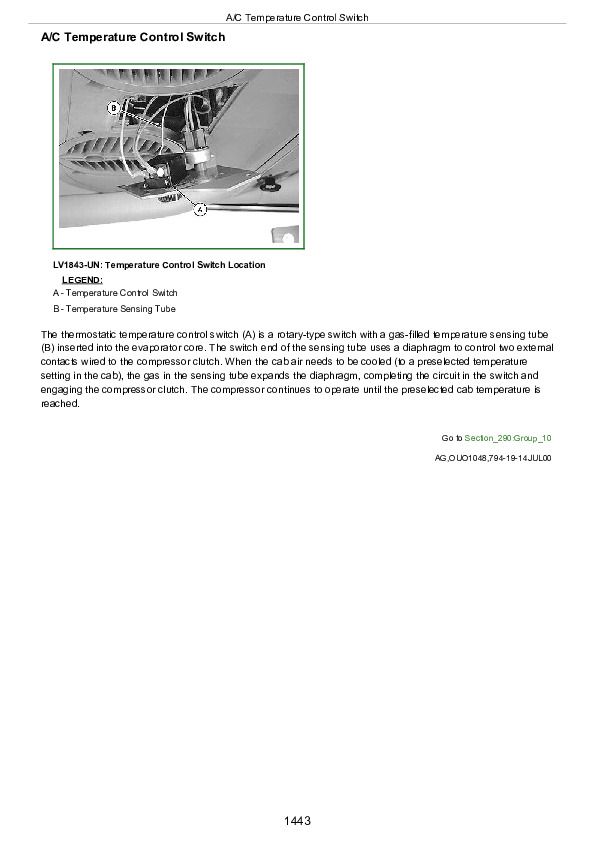
A/C Temperature Control Switch................1443
Evaporator................1444
Heater Temperature Control Knob................1445
High and Low Pressure Switches................1446
Group 15: Diagnosis, Tests, and Adjustments................1429
Diagnosis, Tests and Adjustments................1474
Section 299: Dealer Fabricated Tools................1501
Group 00: Dealer Fabricated Tools................1501
DFLV1A Final Drive Turning Tool................1503
DFRW20 Compressor Holding Fixture................1504
DFRW83 Nozzle Assembly................1505
JDG826 PTO Clutch Finger Height Gauge................1507
JDG827 Traction Clutch Finger Height Gauge................1508
JDG828 Traction Clutch Finger Height Adjustment Tool................1509
TM1717 - Diagnostics and Repair Technical Manual for John Deere Tractors Models 5310N and 5510N.pdf


