John Deere Tractors Models 5210, 5310, 5410 & 5510 Diagnostics & Repair Service Manual (TM1716)
Catalog:
Model:
Complete All Inclusive Technical Manual with electrical wiring diagrams for John Deere Tractors Models 5210, 5310, 5410, 5510, with all the shop information to maintain, diagnose, service, and rebuild like professional mechanics (Diagnosis, Operation, Tests, Repair, Service, Troubleshooting).
John Deere Tractors Models 5210, 5310, 5410, 5510 workshop technical manual includes:
* Numbered table of contents easy to use so that you can find the information you need fast.
* Detailed sub-steps expand on repair procedure information
* Numbered instructions guide you through every repair procedure step by step.
* Troubleshooting and electrical service procedures are combined with detailed wiring diagrams for ease of use.
* Notes, cautions and warnings throughout each chapter pinpoint critical information.
* Bold figure number help you quickly match illustrations with instructions.
* Detailed illustrations, drawings and photos guide you through every procedure.
* Enlarged inset helps you identify and examine parts in detail.
tm1716 - 5210, 5310, 5410, and 5510 tractors diagnostic and repair technical manual Technical Manual.pdf
Total Pages: 1,756 pages
File Format: PDF (bookmarked, ToC, Searchable, Printable)
Language: English
MAIN SECTIONS
Foreword
General Information
Safety
General Specifications
Fuel and Lubricants
Serial Number Locations
Features and Accessories
Engine Repair
Engine
Cooling System
Fuel and Air Repair
Fuel System
Air Intake System
Speed Control Linkage
Electrical Repair
Battery, Starter and Alternator
Electrical System Components
Wiring Harness
Power Train Repair
Clutch Housing
Clutch Assembly-CollarShift/SyncShuttle™ Transmissions
Clutch Assembly-PowrReverser™ Transmission
PowrReverser™
CollarShift/SyncShuttle™ Transmission
PowrReverser™ Transmission
Rear PTO Drive Shaft
Differential
Final Drives
Mechanical Front Wheel Drive
Creeper Assembly
Steering and Brake Repair
Steering Repair
Brake Repair
Hydraulic Repair
Hydraulic Pump and Filter
Hydraulic Oil Cooler
Rockshaft
Dual Selective Control Valve
Single (Third) Selective Control Valve
Hydraulic Mid Mount Coupler
Hydraulic Power Beyond
Miscellaneous Repair
Front Axle-2WD
Wheels
3-Point Hitch
Operator Station Repair
Seat and Support
Control Console and Panel-Tractors Without Cab
ROLL-GARD™
Cab Components
Air Conditioning System
Heating System
Operational Checkout Procedures
Operational Checkout Procedures
Engine Operation, Tests, and Adjustments
Component Location
Theory of Operation
Diagnosis, Tests, and Adjustments
Fuel/Air Operation, Tests, and Adjustments
Component Location
Theory of Operation
Diagnosis, Tests and Adjustments
Electrical System Operation, Tests & Adjust
Component Location
Theory of Operation
Diagnosis, Test and Adjust
Wiring Schematics
Power Train Operation, Tests, and Adjustments
Component Location-Collar Shift and SyncShuttle™ Transmissions
Component Location-PowrReverser™ Transmission
Theory of Operation-Collar Shift and SyncShuttle™ Transmissions
Theory of Operation-PowrReverser™ Transmission
Diagnosis, Tests, and Adjustments-CS/SS Transmissions
Diagnosis, Tests, and Adjustments-PowrReverser™
Steering and Brake Operation, Tests, and Adjustments
Component Location
Theory of Operation
Diagnosis, Tests and Adjustments
Hydraulic System Operation, Tests, and Adjustments
Component Location
Theory of Operation
Diagnosis
Hydraulic Tests-Without SCV
Hydraulic Tests-With SCV
Hydraulic Tests-All
Adjustments
Hydraulic Schematics
Operator Station
Component Location
Theory of Operation
Diagnosis, Tests, and Adjustments
Dealer Fabricated Tools
Dealer Fabricated Tools
TABLE OF CONTENTS
Section 10: General Information................31
Group 05: Safety................31
Recognize Safety Information................35
Understand Signal Words................36
Follow Safety Instructions................37
Handle Fluids Safely-Avoid Fires................38
Prevent Battery Explosions................39
Prepare for Emergencies................40
Prevent Acid Burns................41
Service Cooling System Safely................43
Handle Chemical Products Safely................44
Avoid High-Pressure Fluids................45
Park Machine Safely................46
Support Machine Properly................47
Wear Protective Clothing................48
Work in Clean Area................49
Service Machines Safely................50
Work in Ventilated Area................51
Illuminate Work Area Safely................52
Replace Safety Signs................53
Use Proper Lifting Equipment................54
Keep ROPS Installed Properly................55
Service Tires Safely................56
Avoid Harmful Asbestos Dust................57
Avoid Heating Near Pressurized Fluid Lines................58
Remove Paint Before Welding or Heating................59
Use Proper Tools................60
Dispose of Waste Properly................61
Live With Safety................62
Group 10: General Specifications................1739
Machine Specifications-5210 and 5310................68
Travel Speeds-5210 and 5310................73
Machine Specifications-5410................75
Travel Speeds-5410................78
Machine Specifications-5510................80
Travel Speeds-5510................83
Service Recommendations for O-Ring Boss Fittings................85
Service Recommendations for Flat Face O-Ring Seal Fittings................87
Metric Cap Screw Torque Values-Grade 7................89
Metric Bolt and Cap Screw Torque Values................90
Unified Inch Bolt and Cap Screw Torque Values................92
Abbreviations................94
Group 20: Fuel and Lubricants................32
Diesel Fuel Specifications................1739
Storing Fuel................99
Do Not Use Galvanized Containers................100
Fill Fuel Tank................101
Diesel Engine Oil................102
Diesel Engine Coolant................103
Liquid Coolant Conditioner................105
Transmission and Hydraulic Oil................106
MFWD Gear Oil................107
Grease (Specific Application)................108
Grease................109
Alternative and Synthetic Lubricants................110
Lubricant Storage................111
Group 25: Serial Number Locations................32
Serial Numbers................113
Product Identification Number Location................114
Engine Serial Number Location................115
Fuel Injection Pump Serial Number Location................116
Alternator Serial Number Location................117
Power Steering Valve Serial Number Location................118
Starter Serial Number Location................119
Transmission Serial Number Location................120
Front Axle (2WD) Serial Number Location................121
Mechanical Front Wheel Drive (MFWD) Serial Number Location................122
Air Conditioning Compressor Serial Number Location................123
Group 30: Features and Accessories................125
Features and Accessories................125
Standard Features-5210 and 5310................126
Standard Features-5410 and 5510................128
Standard Features-5210 through 5510................130
Factory Installed Optional Equipment (5210-5510)................131
Field Installed Optional Kits and Accessories-5210 Through 5510................133
Section 20: Engine Repair................135
Group 05: Engine................135
Service Equipment and Tools................1737
Specifications................1739
John Deere Engine Repair-Use CTM104 or CTM125................139
Remove Engine-Tractors without Cab................140
Install Engine-Tractors without Cab................147
Remove Engine-Tractors with Cab................154
Install Engine-Tractors with Cab................165
Group 10: Cooling System................135
Specifications................1739
Engine Water Pump Repair-Use CTM104 or CTM125................177
Remove and Inspect Radiator................178
Install Radiator................182
Replace Thermostat................186
Inspect and Replace Belt Tensioner-Models 5410 and 5510................189
Section 30: Fuel and Air Repair................192
Group 05: Fuel System................192
Specifications................1739
Injection Pump, Nozzle and Governor Repair-Use CTM104 or CTM125................195
Remove, Inspect and Install Fuel Tank-Without Cab................196
Remove, Inspect and Install Fuel Tank-With Cab................200
Replace Fuel Filter-5210 and 5310................204
Remove and Install Fuel Filter/Primer Pump Assembly-5210 and 5310................205
Replace Fuel Filter-5410 and 5510................206
Remove and Install Fuel Filter/Primer Pump Assembly-5410 and 5510................207
Group 10: Air Intake System................192
Other Material................1738
Specifications................1739
Turbocharger Repair-Use CTM104 or CTM125................211
Remove, Inspect, and Install Air Cleaner Elements-5210 and 5310................212
Remove, Inspect, and Install Air Cleaner Elements-5410 and 5510................215
Remove Turbocharger-5310................218
Install Turbocharger-5310................220
Remove Turbocharger-5510................222
Install Turbocharger-5510................224
Turbocharger Break-In................226
Group 15: Speed Control Linkage................192
Inspect and Repair Speed Control Linkage-Without 540/540E PTO................229
Inspect and Repair Speed Control Linkage-With 540/540E PTO................231
Section 40: Electrical Repair................233
Group 05: Battery, Starter and Alternator................233
Starter Repair-Use CTM77................236
Remove and Install Battery-Tractors Without Cab................237
Remove and Install Battery-Tractors With Cab................239
Remove and Install Starter-5210 and 5310................241
Remove and Install Starter-5410 and 5510................243
Replace Alternator/Regulator-40 Amp Without Cab................246
Replace Alternator/Regulator-60 and 65 Amp with Cab................247
Group 10: Electrical System Components................233
Specifications................1739
Service Equipment and Tools................1737
Other Material................1738
Replace Air Filter Restriction Switch-5210 and 5310................253
Replace Air Filter Restriction Switch-5410 and 5510................254
Replace Coolant Temperature Sender-5210 and 5310................255
Replace Coolant Temperature Sender-5410 and 5510................256
Replace Engine Speed Sensor................257
Replace Engine Oil Pressure Switch................258
Replace Air Intake Heater................259
Replace Air Intake Heater Relay................260
Replace Key Switch................262
Replace Tractor Light Switch................264
Replace Radio................266
Replace Speakers................267
Replace Antenna................268
Replace Turn Signal Controller................270
Replace Instrument Panel-CollarShift/SyncShuttle™ Transmission................271
Replace Instrument Panel-PowrReverser™ Transmission................274
Replace Rear PTO Switch-Tractors Without Cab................278
Replace Rear PTO Switch-Tractors With Cab................279
Replace Neutral Start Switch................280
Replace Seat Switch................281
Replace Fuel Level Sender-Tractors Without Cab................283
Replace Fuel Level Sender-Tractors With Cab................284
Replace Wiper Control Switch................288
Replace Wiper Motor................290
Replace Blower Control Switch................291
Replace Air Conditioning Temperature Control Switch................293
Replace Dome Light................296
Replace Dome Light Switch................297
Group 15: Wiring Harness................234
Special or Essential Tools................1736
Service Equipment and Tools................1737
Service Parts Kits................968
Replace Connector Body-Blade Terminals................303
Replace WEATHER PACK WEATHER PACK is a trademark of Packard Electric. Connector................234
Install WEATHER PACK WEATHER PACK is a trademark of Packard Electric. Contact................234
Replace Front Wiring Harness-3 Cylinder................308
Replace Front Wiring Harness-4 Cylinder................310
Replace Rear Wiring Harness-Tractors Without Cab................312
Replace Rear Wiring Harness-Tractors With Cab................314
Replace Cab Wiring Harness-Lights................316
Replace Cab Wiring Harness-Radio/Antenna................318
Replace Cab Wiring Harness-Main................320
Section 50: Power Train Repair................323
Group 05: Clutch Housing................323
Service Equipment and Tools................1737
Specifications................1739
Service Parts Kits................968
Separate Engine from Clutch Housing-Tractors Without Cab................332
Install Engine to Clutch Housing-Tractors Without Cab................338
Separate Engine from Clutch Housing-Tractors With Cab................345
Install Engine to Clutch Housing-Tractors With Cab................353
Replace Clutch Housing Seal................360
Inspect and Repair Clutch Pedal and Linkage-CollarShift/SyncShuttle™................362
Inspect and Repair Clutch Pedal and Linkage-PowrReverser™................364
Group 10: Clutch Assembly-CollarShift/SyncShuttle™ Transmissions................323
Essential Tools................1736
Other Material................1738
Specifications................1739
Service Parts Kits................968
Remove and Install Clutch Assembly................397
Disassemble and Inspect Clutch Assembly................398
Assemble Clutch Assembly................402
Traction Clutch Finger Adjustment................381
PTO Clutch Finger Adjustment................407
Remove and Inspect Clutch Release Mechanism and Shafts................409
Install Clutch Release Mechanism and Shafts................413
Group 11: Clutch Assembly-PowrReverser™ Transmission................323
Essential Tools................1736
Other Material................1738
Specifications................1739
Service Parts Kits................968
Remove and Install Clutch Assembly................397
Disassemble and Inspect Clutch Assembly................398
Assemble Clutch Assembly................402
PTO Clutch Finger Adjustment................407
Remove and Inspect Clutch Release Mechanism and Shafts................409
Install Clutch Release Mechanism and Shafts................413
Remove, Inspect, and Repair Transmission Pump................416
Group 12: PowrReverser™................324
Essential Tools................1736
Specifications................1739
Remove and Install PowrReverser™ Control Valve................421
Disassemble, Inspect, and Repair PowrReverser™ Control Valve................423
Remove and Install PowrReverser™................432
Disassemble, Inspect, and Repair Reverse Idle Gear................437
Disassemble, Inspect, and Repair Clutch Gear................439
Disassemble, Inspect, and Repair Driven Shaft................441
Disassemble, Inspect, and Repair PowrReverser™................443
Group 15: CollarShift/SyncShuttle™ Transmission................324
Service Equipment and Tools................1737
Other Material................1738
Specifications................1739
Separate Clutch Housing from Transmission................453
Install Clutch Housing to Transmission................523
Inspect and Repair Gear Shift Lever................463
Inspect and Repair Range Shift Lever................465
Remove Transmission................528
Disassemble and Inspect Transmission................536
Assemble Transmission................541
Install Transmission................548
Disassemble, Inspect and Assemble Gear Shift Shaft Assemblies................497
Disassemble, Inspect, and Assemble Transmission Top Shaft-CollarShift Transmission................500
Disassemble, Inspect, and Assemble Transmission Top Shaft-SyncShuttle™ Transmission................503
Disassemble, Inspect, and Assemble Range Reduction Shaft................572
Disassemble, Inspect and Assemble Driven Shaft................508
Remove, Inspect, and Install MFWD and Range Gears................510
Remove, Inspect, and Install Reverse Idler Shaft................512
Group 16: PowrReverser™ Transmission................325
Service Equipment and Tools................1737
Other Material................1738
Specifications................1739
Separate Clutch Housing From Transmission................518
Install Clutch Housing to Transmission................523
Remove Transmission................528
Disassemble and Inspect Transmission................536
Assemble Transmission................541
Install Transmission................548
Disassemble, Inspect, and Assemble Gear Shift Shaft Assemblies................567
Disassemble, Inspect, and Assemble Transmission Bottom Shaft................569
Disassemble, Inspect, and Assemble Range Reduction Shaft................572
Disassemble, Inspect, and Assemble Top Shaft................574
Remove, Inspect, Install MFWD and Range Gears................576
Remove, Inspect and Replace Hydraulic Reverser Control Lever................578
Group 20: Rear PTO Drive Shaft................325
Specifications................1739
Remove, Inspect and Install Rear PTO Lever and Linkage................585
Inspect and Repair PTO 540/540E Shift Lever and Linkage................587
Remove and Install Standard Rear PTO Drive Shaft Assembly................589
Disassemble, Inspect and Assemble Standard Rear PTO Drive Shaft Assembly................591
Remove and Install 540/540E Rear PTO Drive Shaft Assembly................594
Disassemble, Inspect, and Assemble Rear 540/540E PTO Drive Shaft Assembly................596
Group 25: Differential................325
Essential Tools................1736
Other Material................1738
Specifications................1739
Service Parts Kits................968
Remove and Install Differential Assembly................605
Disassemble, Inspect, and Assemble Differential Assembly................607
Remove and Inspect Differential Drive Shaft................609
Install Differential Drive Shaft................612
Remove, Inspect, and Install Differential Lock Assembly................616
Differential Cone Point Adjustment................618
Differential Backlash Adjustment................620
Group 30: Final Drives................326
Service Equipment and Tools................1737
Other Material................1738
Specifications................1739
Remove and Install Final Drive Assembly................626
Remove and Inspect Planetary Drive Assembly................628
Install Planetary Drive Assembly................631
Remove, Inspect, and Install Axle Shaft Assembly................634
Group 35: Mechanical Front Wheel Drive................326
Essential Tools................1736
Service Equipment and Tools................1737
Other Material................1738
Specifications................1739
Inspect and Repair MFWD Lever and Linkage................642
Remove and Install MFWD Drop Gearbox................644
Disassemble and Inspect MFWD Drop Gearbox................646
MFWD Drop Gearbox Cross Section................649
Assemble MFWD Drop Gearbox................651
Remove, Inspect and Install MFWD Drive Shaft................656
Remove and Install MFWD Axle Housing Assembly................657
Remove, Inspect and Install MFWD Axle Supports................659
Disassemble and Inspect MFWD Outer Drive................661
Assemble MFWD Outer Drive................665
Remove, Inspect, and Install MFWD Swivel Housing................668
Remove, Inspect, and Install MFWD Axle Shaft................672
Remove and Install MFWD Differential Carrier Assembly................674
Disassemble and Inspect MFWD Differential Carrier Assembly................676
Assemble MFWD Differential Carrier Assembly................681
Group 40: Creeper Assembly................326
Other Material................1738
Specifications................1739
Remove and Install Creeper Assembly................694
Disassemble, Inspect, and Assemble Creeper Assembly................697
Section 60: Steering and Brake Repair................699
Group 05: Steering Repair................699
Other Material................1738
Specifications................1739
Service Parts Kits................968
Remove and Install Steering Column and Valve................704
Disassemble and Inspect Steering Valve................706
Assemble Steering Valve................710
Remove and Install Steering Cylinder-2WD Axle................715
Disassemble, Inspect, and Assemble Steering Cylinder-2WD Axle................716
Remove and Install Steering Cylinder-MFWD Axle................718
Disassemble, Inspect, and Assemble Steering Cylinder-MFWD Axle................720
Remove, Inspect and Install Tie Rod Assembly-2WD Axle................721
Remove, Inspect and Install Tie Rod Assembly-MFWD Axle................723
Inspect and Replace Steering Hydraulic Lines-Without Oil Cooler................725
Inspect and Replace Steering Hydraulic Lines-With Oil Cooler................727
Group 10: Brake Repair................699
Other Material................1738
Specifications................1739
Remove and Install Brake Valve and Pedals................732
Disassemble and Inspect Brake Valve................734
Brake Valve Cross Section................737
Assemble Brake Valve................739
Remove and Inspect Brakes................742
Install Brakes................745
Inspect and Replace Brake Hydraulic Lines................748
Section 70: Hydraulic Repair................750
Group 05: Hydraulic Pump and Filter................750
Specifications................1739
Service Parts Kits................968
Remove, Inspect and Install Hydraulic Oil Pick-Up Screen................755
Remove and Install Hydraulic Pump-5210 and 5310................756
Remove Hydraulic Pump External Components-5210 and 5310................758
Disassemble and Inspect Hydraulic Pump-5210 and 5310................760
Assemble Hydraulic Pump-5210 and 5310................763
Install Hydraulic Pump External Components-5210 and 5310................765
Remove and Install Hydraulic Pump-5410 and 5510................767
Remove Hydraulic Pump External Components-5410 and 5510................769
Disassemble and Inspect Hydraulic Pump-5410 and 5510................771
Assemble Hydraulic Pump-5410 and 5510................774
Install Hydraulic Pump External Components-5410 and 5510................776
Remove and Install Hydraulic Filter/Manifold-Early Model................778
Remove and Install Hydraulic Filter/Manifold-Later Model................779
Inspect and Replace Hydraulic Supply/Return Line................780
Group 06: Hydraulic Oil Cooler................750
Remove, Inspect, and Install Hydraulic Oil Cooler................784
Group 10: Rockshaft................750
Other Material................1738
Specifications................1739
Service Parts Kits................968
Inspect and Repair Rockshaft Control Lever Assembly................790
Inspect and Repair Rockshaft Control Linkage................795
Inspect and Repair Draft Sensing Support Assembly................799
Replace Main Relief Valve................801
Replace Rockshaft Surge Relief Valve................803
Remove, Inspect and Install Rate-of-Drop Valve................804
Replace Rockshaft Control Valve................806
Remove and Install Rockshaft Case................809
Remove, Inspect and Install Rockshaft Lift Arms................811
Remove, Inspect and Install Rockshaft Piston and Cylinder................813
Group 15: Dual Selective Control Valve................751
Other Material................1738
Specifications................1739
Service Parts Kits................968
Inspect and Repair Joystick and Linkage-Without Cab................819
Inspect and Repair Joystick and Linkage-With Cab................822
Remove and Install Dual Selective Control Valve (SCV)................826
Disassemble, Inspect, and Assemble Dual Selective Control Valve (SCV)................829
Inspect and Replace Hydraulic Hoses-Dual Selective Control Valve (SCV)................833
Group 16: Single (Third) Selective Control Valve................751
Other Material................1738
Specifications................1739
Service Parts Kits................968
Inspect and Repair Single (Third) SCV Lever and Linkage................839
Remove and Install Single (Third) Selective Control Valve (SCV)................840
Disassemble, Inspect and Assemble Single (Third) Selective Control Valve (SCV)................842
Inspect and Replace Hydraulic Hoses-Single (Third) Selective Control Valve (SCV)................844
Group 20: Hydraulic Mid Mount Coupler................751
Inspect and Replace Hydraulic Hoses-Mid Mount Coupler Without Cab................848
Inspect and Replace Hydraulic Hoses-Mid Mount Coupler With Cab................850
Group 25: Hydraulic Power Beyond................751
Specifications................1739
Inspect and Replace Power Beyond Hydraulic Lines and Fittings................854
Inspect Power Beyond Motor Control Lines and Fittings................859
Section 80: Miscellaneous Repair................860
Group 05: Front Axle-2WD................860
Specifications................1739
Remove and Install Front Axle-2WD................863
Inspect and Replace Pivot Pin and Bushings-2WD Axle................866
Remove and Install Spindle Assembly-2WD Axle................867
Inspect and Replace Spindle Shaft Bushings-2WD Axle................869
Group 10: Wheels................860
Specifications................1739
Inspect and Replace Front Wheel Bearings................872
Group 15: 3-Point Hitch................860
Specifications................1739
Inspect and Repair Fixed Draft Links................876
Inspect and Repair Telescoping Draft Links................877
Inspect and Repair Standard Lift Link................879
Inspect and Repair Adjustable Lift Link................881
Inspect and Repair Center Link................883
Remove and Install Drawbar and Support................885
Section 90: Operator Station Repair................887
Group 05: Seat and Support................887
Specifications................1739
Remove and Install Seat and Support-Tractors Without Cab................892
Remove and Install Seat and Support Plate-Tractors With Cab................893
Group 06: Control Console and Panel-Tractors Without Cab................887
Remove and Install Right-Side Control Console and Panel-Tractors Without Cab................898
Remove and Install Left-Side Control Console and Panel-Tractors Without Cab................901
Group 10: ROLL-GARDROLL-GARD is a trademark of Deere & Company................887
Specifications................1739
Remove and Install ROLL-GARD ROLL-GARD is a trademark of Deere & Company................887
Group 15: Cab Components................887
Essential Tools................1736
Other Material................1738
Specifications................1739
Remove, Inspect, and Install Cab Interior Recirculating Air Filter................914
Remove, Inspect, and Install Exterior Cab Intake Air Filter................916
Remove and Install Front Headliner................917
Remove and Install Rear Headliner................919
Remove and Install Lower Front Windows................921
Remove and Install Windowpanes................923
Remove and Install Rear Window................924
Remove and Install Cab Doors................926
Remove and Install Cab Roof................928
Remove and Install Right-Side Control Console and Panel-Tractors With Cab................930
Remove and Install Left-Side Control Console-Tractors With Cab................933
Cab Remove and Install................935
Cab Floor Plate Remove and Install-Later Model Tractors................951
Cab Floor Plates Remove and Install-Early Model Tractors................958
Group 20: Air Conditioning System................887
Essential Tools................1736
Service Equipment and Tools................1737
Other Material................1738
Specifications................1739
Service Parts Kits................968
Hose and Tubing O-Ring Connector Torques................969
Recover/Recycle Air Conditioning Refrigerant................970
Replace Air Conditioning Receiver-Dryer................1729
Remove, Inspect, and Install Air Conditioning Condenser................1728
Remove, Inspect, and Install Air Conditioning Compressor................1727
Test Volumetric Efficiency of Compressor................1727
Test Compressor Shaft Seal Leakage................982
Disassemble and Assemble Compressor Clutch................984
Disassemble, Inspect, and Assemble Compressor................1727
Check Compressor Clutch Hub Clearance................989
Inspect Compressor Manifold................990
Remove and Install Compressor Relief Valve................991
Remove and Install Evaporator/Heater Core Housing Cover................992
Remove Blower Motors................996
Remove Evaporator/Heater Core................998
Leak Test Evaporator/Heater Core................1000
Install Evaporator/Heater Core................1001
Service Expansion Valve................1730
Expansion Valve Bench Test-Diagram................1004
Expansion Valve Bench Test................1006
Refrigerant Oil Information................1007
Check Compressor Oil Charge................1008
Determine Correct Refrigerant Oil Charge................1009
Add Refrigerant Oil to System................1011
System Information................1012
Flush Air Conditioning System................1013
Evacuate Air Conditioning System................1016
Charge Air Conditioning System................1018
Group 25: Heating System................888
Replace Heater Temperature Control and Cable................1026
Remove, Test, and Install Heater Control Valve................1035
Leak Test Heater Control Valve................1034
Install Heater Control Valve................1035
Section 210: Operational Checkout Procedures................1036
Group 10: Operational Checkout Procedures................1036
Operational Checkout Procedure Information................1039
Engine Oil Level and Condition Check................1040
Coolant Level and Condition Check................1041
Transmission and Hydraulic Oil Check................1042
Fan and V-Belt Check-5210 and 5310................1043
Fan and Serpentine Belt Check-5410 and 5510................1044
Compressor Belt Check................1045
Fuel System Check................1047
Air Intake System Check................1049
Electrical System Check................1051
Hydraulic System Check................1052
MFWD Oil Check................1053
Indicator Lamps Check................1054
Cab Blower Motor Check................1055
A/C Compressor Clutch Check................1065
Engine Start Check................1057
Transmission Neutral Start Check................1058
PTO Neutral Start Check................1060
Engine Fast and Slow Idle Operation................1061
Power Steering Check................1062
Differential Lock Check................1063
PTO Engagement Check................1064
Clutch Check................1065
Transmission Shift Check................1066
Range Lever Shift Check................1067
MFWD Drive Check................1069
Brake Check................1070
Rockshaft Check................1071
Selective Control Valve Check................1072
A/C System Operational Check................1074
Cab Heater Valve Check................1075
Miscellaneous Checks................1076
Section 220: Engine Operation, Tests, and Adjustments................1077
Group 05: Component Location................1077
Component Location Information................1611
Engine External Components-Left-Hand Side................1081
Engine External Components-Right-Hand Side................1083
4-Cylinder Engine External Components-Left-Hand Side................1081
4-Cylinder Engine External Components-Right-Hand Side................1083
Group 10: Theory of Operation................1077
Theory of Operation Information................1619
Engine Lubrication System Operation................1091
Engine Lubrication System Operation-Continued................1093
Engine Cooling System Operation-3-Cylinder................1095
Engine Cooling System Operation-4-Cylinder................1097
Group 15: Diagnosis, Tests, and Adjustments................1740
Diagnostic Information................1658
Engine Turns Over But Will Not Start or Starts Hard................1101
Engine Runs Irregularly or Stalls Frequently................1102
Engine Runs Rough................1103
Engine Has Low Power................1104
Engine Smokes-Black or Grey................1106
Engine Smokes Excessively-White................1107
Engine Uses Excess Fuel................1108
Engine Has Excess Noise or Vibration................1109
Engine Uses Excess Oil or Smokes Blue................1110
Engine Has Low Oil Pressure................1111
Engine Coolant Operating Temperature Incorrect................1112
Oil In Coolant or Coolant in Oil................1113
Radiator Bubble Test................1114
Cooling System Test................1116
Radiator Cap Pressure Test................1117
Engine Oil Pressure Test................1118
Cylinder Compression Pressure Test................1120
Fuel Shut-Off Solenoid Check................1122
Throttle Lever Adjustment................1123
Slow Idle Adjustment................1124
Fast Idle Adjustment................1126
Injection Pump Timing Adjustment................1128
Check and Adjust Valve Clearance................1130
Fan/Alternator V-Belt Adjustment (5210 and 5310)................1134
Compressor Drive Belt Adjustment-3-Cylinder................1136
Turbocharger Boost Pressure Test-5310 and 5510................1138
Bleed Fuel System................1140
Section 230: Fuel/Air Operation, Tests, and Adjustments................1143
Group 05: Component Location................1143
Component Location Information................1611
Fuel System Components................1146
Air Intake System Components-Without Turbocharger................1148
Air Intake System Components-With Turbocharger................1150
Group 10: Theory of Operation................1143
Theory of Operation Information................1619
Fuel System Operation................1154
Fuel Filter/Priming Pump Operation................1156
Fuel Injection Nozzle Operation................1158
Air Intake System Operation-Without Turbocharger................1160
Air Intake System Operation-With Turbocharger................1162
Turbocharger Operation-5310 and 5510................1164
Group 15: Diagnosis, Tests and Adjustments................1143
Diagnostic Information................1658
Fuel/Air Diagnosis, Tests and Adjustments................1168
Section 240: Electrical System Operation, Tests Section 240: Electrical System Operation, Tests & Adjust{pgNO}1169 Adjust................1169
Group 05: Component Location................1169
Component Location Information................1611
Engine Electrical Components-4-Cylinder................1174
Dash Electrical Components................1176
Machine Electrical Components-5210-5410 Without Cab................1178
Machine Electrical Components-5510 Without Cab................1180
Machine Electrical Components-5210-5510 With Cab................1182
Cab Control Panel and Electrical Components................1184
Group 10: Theory of Operation................1169
Theory of Operation Information................1619
Fuse Block and Fuses-Without Cab................1188
Fuse Block and Fuses-With Cab................1190
Cab Fuse Block and Fuses................1192
Relays................1194
Starting System Operation-Normal................1195
Starting System Operation-Bypass Attempt................1198
Manifold Heater System Operation................1200
Charging System Operation................1202
Lighting System Operation-Turn Signals................1204
Lighting System Operation-Warning Lights................1206
Lighting System Operation-Tail Light................1208
Lighting System Operation-Headlights and Instrument Lights................1210
Instrument Panel System Operation-Tachometer................1212
Instrument Panel System Operation-Fuel Gauge................1214
Instrument Panel System Operation-Temperature Gauge................1216
Instrument Panel System Operation-Hourmeter................1218
PTO Warning System Operation................1220
Air Filter Restriction Indicator Operation................1222
Rear Work Light Operation-Without Cab................1224
Optional Horn Operation................1226
Accessory Relay and Trailer Connector Operation................1227
Flood Light Operation-With Cab................1229
Blower Motor Operation-With Cab................1231
A/C Compressor Operation-Cab Only................1234
Front Wiper/Washer Operation-Cab Only................1237
Rear Wiper/Washer Operation-Cab Only................1239
Dome Light Operation-Cab Only................1241
Group 15: Diagnosis, Test and Adjust................1170
Diagnostic Information................1658
Wire Color Chart................1245
Starting System Test Points-Normal Operation................1247
Starting System Test Points-Bypass Attempt................1251
Manifold Heater Test Points................1254
Charging System Test Points................1257
Lighting System Test Points-Turn Signals (Tractors Without Cab)................1260
Lighting System Test Points-Turn Signals (Tractors With Cab)................1263
Lighting System Test Points-Warning Lights (All Tractors)................1268
Lighting System Test Points-Rear Work Light (Tractors Without Cab)................1271
Lighting System Test Points-Flood Lights (Tractors With Cab)................1274
Lighting System Test Points-Tail Lights (Tractors Without Cab)................1278
Lighting System Test Points-Tail Lights (Tractors With Cab)................1281
Lighting System Test Points-Headlights and Instrument Lights................1284
Lighting System Test Points-Dome Light (Tractors With Cab)................1288
Instrument Panel System Test Points-Tachometer/Hourmeter................1291
Instrument Panel System Test Points-Fuel Gauge................1294
Instrument Panel System Test Points-Temperature Gauge................1297
Instrument Panel System Test Points-Oil Pressure................1300
PTO Warning System Test Points................1303
Air Filter Restriction Test Points................1306
Optional Horn Test Points................1309
Accessory Relay and Trailer Connector Test Points................1311
Blower Motor Test Points (Tractors With Cab)................1314
A/C Compressor Clutch Coil Test Points (Tractors With Cab)................1319
Front Wiper/Washer Test Points (Tractors With Cab)................1321
Rear Wiper/Washer Test Points (Tractors With Cab)................1324
Battery Voltage and Specific Gravity Tests................1327
Charge Battery................1329
Battery Load Test................1331
Starter Amp Draw/RPM Test................1333
Starter No-Load Amp Draw/RPM Test................1335
Alternator/Regulator Test................1337
Starter Solenoid Test................1339
Starter Relay Test................1340
Key Switch Test................1342
Plug-In Relay Test................1344
Diode Pack Test................1346
Fuse Test................1348
Neutral Start Switch Test................1349
PTO Switch Test................1350
PTO Seat Switch Test................1352
Light Switch Test................1353
Turn Signal Controller Test................1354
Fuel Shut-Off Solenoid Test................1355
Blower Switch Test................1356
Blower Motor Resistors................1358
A/C Thermostatic Control Switch Test................1360
Front Wiper/Washer Switch Test................1361
Rear Wiper/Washer Switch Test................1362
Door Switch Test................1363
Dome Light Switch Test................1364
Group 20: Wiring Schematics................1171
Schematic Information................1366
Component Identification Table................1367
5210-5510 Electrical Schematics and Legend (Tractors Without Cab)................1171
5210-5510 Electrical Schematic and Legend (Tractors With Cab)................1171
Section 250: Power Train Operation, Tests, and Adjustments................1380
Group 05: Component Location-Collar Shift and SyncShuttle™ Transmissions................1380
Component Location Information................1611
Power Train Components................1386
Clutch Components................1388
Transmission Components-Collar Shift................1390
Transmission Components-SyncShuttle™ (SS)................1392
Final Drive Components................1407
Rear PTO Components................1408
Rear 540/540E PTO Components (SyncShuttle™ Transmission Only)................1396
Group 06: Component Location-PowrReverser™ Transmission................1380
Component Location Information................1611
Power Train Components-PowrReverser™ Transmission................1399
Clutch Components-PowrReverser™ Transmission................1401
PowrReverser™ Components................1403
Transmission Components-PowrReverser™ Transmission................1405
Final Drive Components................1407
Rear PTO Components................1408
Group 10: Theory of Operation-Collar Shift and SyncShuttle™ Transmissions................1380
Theory of Operation Information................1619
Clutch Operation................1411
Transmission Lubrication System................1418
Transmission Power Flow-Gear Shift (Collar)................1420
Transmission Power Flow-Gear Shift (SyncShuttle™)................1422
SyncShuttle™ Transmission Synchronizer Operation-Reverse and 2nd Gear (Disk-and-Plate Type Synchronizer)................1424
SyncShuttle™ Transmission Synchronizer Operation-1st and 3rd Gear (Cone-Type Synchronizer)................1426
Transmission Power Flow-Range Shift................1471
Rear PTO Operation................1476
Rear 540/540E PTO Operation (SyncShuttle™ Transmission Only)................1433
Differential Power Flow................1435
Differential Lock Operation................1437
Final Drive Operation................1477
Mechanical Front Wheel Drive (MFWD) Operation................1441
Group 11: Theory of Operation-PowrReverser™ Transmission................1381
Theory of Operation Information................1619
Clutch Operation-PTO Clutch Engaged (PowrReverser™ Transmission)................1445
Clutch Operation-PTO Clutch Disengaged (PowrReverser™ Transmission)................1447
PowrReverser™ General Information................1449
PowrReverser™ Operation in Forward................1450
PowrReverser™ Operation in Reverse................1452
PowrReverser™ Power Flow................1454
PowrReverser™ Control Valve Operation-Initial Engine Start-Up, Clutch Pedal Up................1456
PowrReverser™ Control Valve Operation-F-N-R Lever in Neutral, Clutch Pedal Down................1458
PowrReverser™ Control Valve Operation-F-N-R Lever in Neutral, Clutch Pedal Up................1460
PowrReverser™ Control Valve Operation-F-N-R Lever in Forward, Clutch Pedal Up................1462
PowrReverser™ Control Valve Operation-F-N-R Lever in Reverse, Clutch Pedal Up................1465
Transmission Power Flow-Gear Shift................1467
Gear Shift Synchronizer Operation................1469
Transmission Power Flow-Range Shift................1471
PowrReverser™ Transmission Lubrication System................1474
Rear PTO Operation................1476
Final Drive Operation................1477
Differential Operation................1478
MFWD Operation................1479
Group 15: Diagnosis, Tests, and Adjustments-CS/SS Transmissions................1381
Diagnostic Information................1658
Isolate the Problem Area................1521
Traction Clutch Slips................1484
Traction Clutch Dragging................1485
Traction Clutch Does Not Engage................1486
Traction Clutch Grabs................1487
Traction Clutch Squeaks................1488
Traction Clutch Does Not Release................1489
Traction Clutch Chatters................1490
Traction Clutch Rattles................1491
Traction Clutch Engagement Is Noisy................1492
Excessive Vibration in Traction Clutch................1493
Clutch Pedal Does Not Return................1525
Clutch Pedal Loose................1495
Clutch Pedal Pulsates................1496
Jerky or Rough Transmission of Power................1497
Low Transmission Oil Level (Excessive Oil Leakage)................1524
Gears Clash, Shift Hard, or Will Not Engage................1529
Two Speeds Engage Together................1530
Transmission Will Not Stay in Gear................1531
Transmission Noisy................1532
PTO Noisy................1503
PTO Hard to Engage................1504
PTO Will Not Operate................1505
PTO Will Not Stay Engaged................1506
Excessive Differential Noise................1507
Differential Does Not Work................1508
No Differential Lock................1509
Differential Chatters................1510
Axle Noise................1511
Axle Shaft Will Not Turn................1512
MFWD Lever is Hard to Engage................1513
MFWD Lever Will Not Stay in “ON” Position................1514
Noisy Front Wheel Drive Operation................1515
Clutch Pedal Free Play Adjustment................1516
PTO Clutch Lever Adjustment................1517
Group 16: Diagnosis, Tests, and Adjustments-PowrReverser™................1382
Diagnostic Information................1658
Isolate the Problem Area................1521
Low Transmission Oil Level (Excessive Oil Leakage)................1524
Clutch Pedal Does Not Return................1525
Tractor Does Not Move in Forward or Reverse................1526
PowrReverser™ Engages Too Quickly or Too Slowly................1527
PowrReverser™ Does Not Disengage................1528
Gears Clash, Shift Hard, or Will Not Engage................1529
Two Speeds Engage Together................1530
Transmission Will Not Stay in Gear................1531
Transmission Noisy................1532
PTO Troubleshooting................1533
Differential Troubleshooting................1534
Axle Troubleshooting................1535
MFWD Troubleshooting................1536
PowrReverser™ Control Valve Tests................1537
Transmission Pump Flow Test................1543
Forward-Neutral-Reverse Control Cable Adjustment................1545
Clutch Pedal Linkage Adjustment................1552
Park Brake Cable Adjustment................1554
PTO 540/540E Lever and Linkage Adjustment................1557
Section 260: Steering and Brake Operation, Tests, and Adjustments................1559
Group 05: Component Location................1559
Component Location Information................1611
Steering System Components-5210, 5310, and 5410 Without Cab................1562
Steering System Components-5510 and All Cab Units................1564
Brake System Components................1566
Group 10: Theory of Operation................1559
Theory of Operation Information................1619
Steering System Operation-5210, 5310, and 5410 Without Cab................1570
Steering System Operation-5510 and All Cab Units................1572
Steering Valve Operation-Neutral and Manual Turning................1574
Steering Valve Operation-Power Turning................1576
Brake System Operation................1578
Brake Valve Operation................1580
Group 15: Diagnosis, Tests and Adjustments................1559
Diagnostic Information................1658
Isolate the Problem-Steering System................1586
Steering Sluggish or Loss of Steering................1587
Isolate the Problem-Brakes................1588
Excessive Brake Pedal Leak-Down................1589
Excessive Brake Chatter................1590
Steering Pump Flow Test................1591
Steering Valve Relief Test................1593
Steering Cylinder Leakage Test................1594
Steering Valve Leakage Test................1595
Toe-In Check and Adjustment-Standard Axle................1597
Toe-In Check and Adjustment-MFWD................1599
MFWD Steering Stop Adjustment................1601
Brake Pedal Adjustment................1602
Adjust Brake Drag................1604
Bleed Brake System................1606
Section 270: Hydraulic System Operation, Tests, and Adjustments................1607
Group 05: Component Location................1607
Component Location Information................1611
Hydraulic System Components-Without Oil Cooler................1612
Hydraulic System Components-With Oil Cooler................1614
Selective Control Valve Components................1616
Group 10: Theory of Operation................1607
Theory of Operation Information................1619
Hydraulic System Operation................1620
Hydraulic Filter Operation-Early Model................1623
Hydraulic Filter Operation-Later Model................1625
Hydraulic Pump Operation................1627
Rockshaft Control Valve Operation-Two Flow Regulator Valves................1629
Rockshaft Control Valve Operation-Neutral Position................1631
Rockshaft Control Valve Operation-Raise Position................1633
Rockshaft Control Valve Operation-Lower Position................1635
Surge Relief Valve Operation................1637
Main Relief Valve Operation................1639
Rate-of-Drop Valve Operation-Full Open................1641
Rate-of-Drop Valve Operation-Full Closed................1643
Rockshaft Draft-Sensing Operation................1645
Selective Control Valve Operation-Neutral Position................1647
Selective Control Valve Operation-Extend and Retract Positions................1649
Selective Control Valve Operation-Boom Spool Float Position................1651
Selective Control Valve Operation-Bucket Spool Regenerative Position................1653
Quick Disconnect Coupler Operation................1655
Group 15: Diagnosis................1607
Diagnostic Information................1658
Preliminary Hydraulic System Inspection................1659
Hydraulic Oil Warm-Up Procedure................1660
Entire Hydraulic System Fails to Function/No Hydraulic Pump Output................1661
Insufficient Pump Delivery................1662
Hydraulic Functions Too Slow................1663
Excessive Pump Pressure................1664
Slow Hydraulic Pump Response................1665
Excessive Pump Noise During Operation................1666
Rockshaft Does Not Lift or Lifts Slowly................1667
Rockshaft Does Not Lower or Lowers Slowly................1668
Neutral Position Unstable, Rockshaft Drops after Engine Shut Down................1669
SCV Joystick Does Not Return to Neutral Position-Single (Third) SCV................1670
SCV Joystick Does Not Return to Neutral Position-Dual SCV................1671
SCV Joystick Does Not Remain in Detent Position-Dual SCV................1672
Remote Cylinder Does Not Extend or Retract................1673
Remote Cylinder Settles Under Load................1674
Remote Cylinder Operates Too Fast or Too Slow................1675
Group 16: Hydraulic Tests-Without SCV................1608
Hydraulic System Tests-Without SCV................1678
Pump Flow Test-Without SCV................1680
Main Relief Valve Test-Without SCV................1682
Group 17: Hydraulic Tests-With SCV................1608
Hydraulic System Tests-With SCV................1686
Pump Flow Test-With SCV................1688
Main Relief Valve Test-With SCV................1690
SCV Leakage Test................1691
Group 18: Hydraulic Tests-All................1608
Rockshaft Leakage Test................1695
Rockshaft Lift Cycle Test................1697
Group 19: Adjustments................1608
Rockshaft Control Lever Friction Adjustment................1700
Rockshaft Position-Sensing Feedback Linkage Adjustment................1701
Rockshaft Draft-Sensing Feedback Linkage Adjustment................1705
Main Relief Valve Adjustment................1707
Group 20: Hydraulic Schematics................1608
Hydraulic Circuit Symbols................1710
Hydraulic Schematic-Without Selective Control Valves................1712
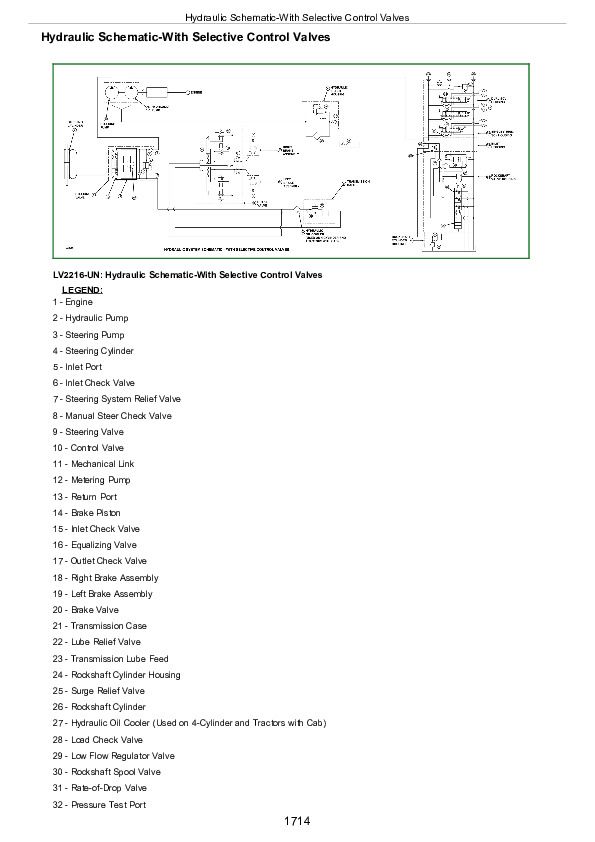
Hydraulic Schematic-With Selective Control Valves................1714
Power Beyond Hydraulic Schematic................1716
Section 290: Operator Station................1717
Group 05: Component Location................1717
Air Conditioning System Components................1720
Group 10: Theory of Operation................1717
Refrigerant R134a................1723
Air Conditioning System Air Flow................1724
Air Conditioning System Cycle................1725
Compressor................1727
Condenser................1728
Receiver-Dryer................1729
Expansion Valve................1730
A/C Temperature Control Switch................1731
Evaporator................1732
Heater Temperature Control Knob................1733
High and Low Pressure Switches................1734
Group 15: Diagnosis, Tests, and Adjustments................1740
Essential Tools................1736
Service Equipment and Tools................1737
Other Material................1738
Specifications................1739
Diagnosis, Tests, and Adjustments................1740
Adjust Heater Temperature Control Cable................1767
Section 299: Dealer Fabricated Tools................1769
Group 00: Dealer Fabricated Tools................1769
JDG826-PTO Clutch Finger Height Gauge................1771
JDG827-Traction Clutch Finger Height Gauge................1772
JDG828-Traction Clutch Finger Height Adjustment Tool................1773
JDG919-Clutch Finger Height Gauge................1774
DFLV1A-Final Drive Turning Tool................1775
DFRW83-Nozzle Assembly................1776
DFRW20-Compressor Holding Fixture................1778
John Deere Tractors Models 5210, 5310, 5410 & 5510 Diagnostics & Repair Service Manual (TM1716)


