TM1792 - Diagnostics and Repair Technical Manual for John Deere Tractors Models 5105 and 5205
Catalog:
Model:
Diagnostics and Repair Technical for John Deere Tractors 5105, 5205, with technical information to maintain, diagnose, and repair like professional mechanics.
All Inclusive Technical Manual (Diagnosis Operation Tests Repair Service) for John Deere Tractors 5105 and 5205 Series includes:
* Numbered table of contents easy to use so that you can find the information you need fast.
* Detailed sub-steps expand on repair procedure information
* Numbered instructions guide you through every repair procedure step by step.
* Troubleshooting and electrical service procedures are combined with detailed wiring diagrams for ease of use.
* Notes, cautions and warnings throughout each chapter pinpoint critical information.
* Bold figure number help you quickly match illustrations with instructions.
* Detailed illustrations, drawings and photos guide you through every procedure.
* Enlarged inset helps you identify and examine parts in detail.
TM1792 - John Deere Tractors 5105 and 5205 Diagnostics and Repair Technical Manual.pdf
Total Pages: 1,212 pages
FFile Format: PDF (bookmarked, ToC, Searchable, Printable)
Language: English
MAIN SECTIONS
Foreword
General Information
Safety
General Specifications
Fuel and Lubricants
Serial Number Locations
Features and Accessories
Engine Repair
Engine
Cooling System
Fuel and Air Repair
Fuel System
Air Intake System
Speed Control Linkage
Electrical Repair
Battery, Starter and Alternator
Electrical System Components
Wiring Harness
Power Train Repair
Clutch Housing
Clutch Assembly
Transmission
Rear PTO
Differential
Final Drives
Mechanical Front Wheel Drive
Steering and Brake Repair
Steering Repair
Brake Repair
Hydraulic Repair
Hydraulic Pump and Filter
Rockshaft
Selective Control Valve (SCV)
Hydraulic Mid Mount Coupler
Miscellaneous Repair
Front Axle-2WD
Wheels
3-Point Hitch
Operator Station Repair
Seat and Support
ROLL-GARD™
Operator Platform
Fenders
Operational Checkout Procedures
Operational Checkout Procedures
Engine Operation, Tests and Adjustments
Component Location
Theory of Operation
Diagnosis, Tests and Adjustments
Fuel/Air Operation, Tests and Adjustments
Component Location
Theory of Operation
Diagnosis, Tests and Adjustments
Electrical System Operation, Tests & Adjust
Component Location
Theory of Operation
Diagnosis, Test and Adjust
Wiring Schematics
Power Train Operation, Tests & Adjustments
Component Location-Power Train
Theory of Operation-Transmission
Diagnosis, Tests and Adjustments-Power Train
Steering and Brake Operation, Test & Adjust
Component Location
Theory of Operation
Diagnosis, Tests and Adjustments
Hydraulic System Operation, Test & Adjust
Component Location
Theory of Operation
Diagnosis
Hydraulic Tests-Without SCV
Hydraulic Tests-With SCV
Hydraulic Tests-With Mid Mount Control Valve
Hydraulic Tests-All
Adjustments
Hydraulic Schematics
Dealer Fabricated Tools
TABLE OF CONTENTS
Section 10: General Information................23
Group 05: Safety................23
Recognize Safety Information................27
Understand Signal Words................28
Follow Safety Instructions................29
Handle Fluids Safely-Avoid Fires................30
Prevent Battery Explosions................31
Prepare for Emergencies................32
Prevent Acid Burns................33
Service Cooling System Safely................35
Handle Chemical Products Safely................36
Avoid High-Pressure Fluids................37
Park Machine Safely................38
Support Machine Properly................39
Wear Protective Clothing................40
Work in Clean Area................41
Service Machines Safely................42
Work in Ventilated Area................43
Illuminate Work Area Safely................44
Replace Safety Signs................45
Use Proper Lifting Equipment................46
Keep ROPS Installed Properly................47
Service Tires Safely................48
Avoid Harmful Asbestos Dust................49
Avoid Heating Near Pressurized Fluid Lines................50
Remove Paint Before Welding or Heating................51
Use Proper Tools................52
Dispose of Waste Properly................53
Live With Safety................54
Group 10: General Specifications................1051
Machine Specifications................1051
Drain and Refill Capacities................59
Machine Dimensions................60
Ground Speed Estimates................61
Service Recommendations for O-Ring Boss Fittings................64
Service Recommendations for Flat Face O-Ring Seal Fittings................66
Metric Bolt and Cap Screw Torque Values................68
Unified Inch Bolt and Cap Screw Torque Values................70
Group 20: Fuel and Lubricants................24
Diesel Fuel................74
Fuel Storage................76
Do Not Use Galvanized Containers................77
Fill Fuel Tank................78
Diesel Engine Oil................79
Engine Coolant................80
Liquid Coolant Conditioner................81
Transmission and Hydraulic Oil................82
MFWD Gear Oil................83
Grease (Specific Application)................84
Grease................85
Alternative and Synthetic Lubricants................86
Lubricant Storage................87
Group 25: Serial Number Locations................24
Serial Numbers................89
Product Identification Number Location................90
Engine Serial Number Location................91
Fuel Injection Pump Serial Number Location................92
Alternator Serial Number Location................93
Power Steering Valve Serial Number Location................94
Starter Serial Number Location................95
Transmission Serial Number Location................96
Front Axle (2WD) Serial Number Location................97
Mechanical Front Wheel Drive (MFWD) Serial Number Location................98
Group 30: Features and Accessories................100
Features and Accessories................100
Standard Features................101
Factory Installed Optional Equipment................104
Field Installed Optional Kits and Accessories................106
Section 20: Engine Repair................107
Group 05: Engine................107
Service Equipment and Tools................458
Specifications................1051
John Deere Engine Repair-Use CTM8................111
Remove Engine................112
Install Engine................120
Group 10: Cooling System................107
Specifications................1051
Engine Water Pump Repair-Use CTM8................130
Remove, Inspect and Install Radiator................131
Replace Thermostat................134
Section 30: Fuel and Air Repair................136
Group 05: Fuel System................136
Specifications................1051
Injection Pump, Nozzle and Governor Repair-Use CTM8................139
Remove, Inspect and Install Fuel Tank................140
Replace Fuel Filter................142
Remove and Install Fuel Filter/Primer Pump Assembly................143
Group 10: Air Intake System................136
Remove, Inspect, and Install Air Cleaner Elements................146
Group 15: Speed Control Linkage................136
Inspect and Repair Speed Control Linkage................150
Section 40: Electrical Repair................152
Group 05: Battery, Starter and Alternator................152
Starter Repair-Use CTM77................154
Remove and Install Battery................155
Remove and Install Starter................157
Replace Alternator/Regulator................159
Group 10: Electrical System Components................152
Service Equipment and Tools................458
Other Material................526
Specifications................1051
Replace Air Filter Restriction Sensor................164
Replace Coolant Temperature Sender................165
Replace Engine Speed Sensor................166
Replace Engine Oil Pressure Sensor................167
Replace Key Switch................168
Replace Light Switch (S.N. -510008)................170
Replace Light Switch (S.N. 510009- )................172
Replace Turn Signal Controller................174
Replace Instrument Panel (S.N. -510008)................175
Replace Instrument Panel (S.N. 510009- )................178
Replace Rear PTO Switch................180
Replace Neutral Start Switch................181
Replace Seat Switch................182
Replace Fuel Level Sender................183
Group 15: Wiring Harness................152
Special or Essential Tools................652
Service Parts Kits................440
Remove Connector Body from Blade Terminals................188
Replace WEATHER PACK WEATHER PACK is a trademark of Packard Electric. Connector................152
Install WEATHER PACK WEATHER PACK is a trademark of Packard Electric. Contact................152
Replace Tractor Wiring Harness................193
Section 50: Power Train Repair................196
Group 05: Clutch Housing................196
Specifications................1051
Separate Engine from Transmission Housing................201
Install Engine to Transmission Housing................205
Inspect and Repair Clutch Pedal and Linkage................208
Group 10: Clutch Assembly................196
Other Material................526
Essential Tools................652
Specifications................1051
Remove and Install Clutch Assembly................214
Disassemble and Inspect Clutch Assembly................217
Assemble Clutch Assembly................226
Traction Clutch Finger Adjustment................233
PTO Clutch Finger Adjustment................235
Remove and Inspect Clutch Release Mechanism and Shafts................237
Install Clutch Release Mechanism and Shafts................241
Group 15: Transmission................196
Other Material................526
Specifications................1051
Remove, Inspect and Repair Gear Shift Lever And Cover................247
Remove, Inspect and Install Range and Reverse Shift Lever................249
Remove Transmission................251
Disassemble and Inspect Transmission................254
Assemble Transmission................260
Install Transmission................266
Disassemble, Inspect and Assemble Shift Shaft Assemblies................268
Disassemble, Inspect, and Assemble Transmission Main Driven Shaft................270
Disassemble, Inspect and Assemble Range Reduction Shaft................272
Disassemble, Inspect and Assemble Driven Shaft................275
Disassemble, Inspect and Assemble Traction Clutch Driven Shaft................277
Disassemble, Inspect and Assemble Synchronizer................279
Group 20: Rear PTO................197
Other Material................526
Specifications................1051
Remove, Inspect and Install Rear PTO Lever and Linkage................284
Remove and Install Rear PTO Drive Shaft Assembly................287
Disassemble, Inspect and Assemble Rear PTO Drive Shaft Assembly................289
Group 25: Differential................197
Essential Tools................652
Other Material................526
Specifications................1051
Remove and Install Differential Assembly................296
Disassemble, Inspect and Assemble Differential Assembly................298
Remove and Inspect Differential Drive Shaft................300
Install Differential Drive Shaft................304
Remove, Inspect and Install Differential Lock Assembly................309
Differential Cone Point Adjustment................311
Differential Backlash Adjustment................313
Group 30: Final Drives................197
Essential Tools................652
Service Equipment and Tools................458
Other Material................526
Specifications................1051
Remove and Install Final Drive Assembly................320
Remove and Inspect Planetary Drive Assembly................322
Install Planetary Drive Assembly................325
Remove, Inspect, and Install Axle Shaft Assembly................328
Group 35: Mechanical Front Wheel Drive................197
Essential Tools................652
Other Material................526
Specifications................1051
Inspect and Repair MFWD Lever and Linkage................336
Remove and Install MFWD Drop Gearbox................337
Disassemble and Inspect MFWD Drop Gearbox................340
Remove, Inspect and Install MFWD Drive Shaft................347
Remove and Install MFWD Axle Housing Assembly................348
Remove, Inspect and Install MFWD Axle Supports................350
Disassemble and Inspect MFWD Outer Drive................352
Assemble MFWD Outer Drive................356
Remove, Inspect and Install MFWD Swivel Housing................359
Remove, Inspect and Install MFWD Axle Shaft................364
Remove and Install MFWD Differential Carrier Assembly................366
Disassemble and Inspect MFWD Differential Carrier Assembly................368
Assemble MFWD Differential Carrier Assembly................373
Section 60: Steering and Brake Repair................384
Group 05: Steering Repair................384
Other Material................526
Specifications................1051
Service Parts Kits................440
Remove and Install Steering Column and Valve................389
Disassemble and Inspect Steering Valve................391
Assemble Steering Valve................395
Remove and Install Steering Cylinder-2WD Axle with Adjustable Steering Cylinder................400
Remove and Install Steering Cylinder-2WD Axle without Adjustable Steering Cylinder................402
Disassemble, Inspect and Assemble Steering Cylinder-2WD Axle with Adjustable Steering Cylinder................404
Disassemble, Inspect and Assemble Steering Cylinder-2WD Axle without Adjustable Steering Cylinder................406
Remove and Install Steering Cylinder-MFWD Axle (5105 S.N. -411494) (5205 S.N. -421397)................408
Remove and Install Steering Cylinder-MFWD Axle (5105 S.N. 411495- ) (5205 S.N. 412398- )................410
Disassemble, Inspect and Assemble Steering Cylinder-MFWD Axle................412
Remove, Inspect and Install Tie Rod Assembly-2WD Axle with Adjustable Steering Cylinder................413
Remove, Inspect and Install Tie Rod Assembly-2WD Axle without Adjustable Steering Cylinder................415
Remove, Inspect and Install Tie Rod Assembly-MFWD Axle................417
Inspect and Replace Steering Hydraulic Lines-Tractor With 2WD................419
Inspect and Replace Steering Hydraulic Lines-Tractor With MFWD................421
Group 10: Brake Repair................384
Other Material................526
Specifications................1051
Remove and Install Brake Pedals and Linkage................426
Remove and Install Park Brake Lever and Linkage................428
Remove and Inspect Brakes................429
Install Brakes................431
Section 70: Hydraulic Repair................435
Group 05: Hydraulic Pump and Filter................435
Service Equipment and Tools................458
Specifications................1051
Service Parts Kits................440
Remove, Inspect, and Install Hydraulic Oil Pick-Up Screen................441
Remove and Install Hydraulic Pump................442
Remove Hydraulic Pump External Components................444
Disassemble and Inspect Hydraulic Pump................446
Assemble Hydraulic Pump................449
Install Hydraulic Pump External Components................451
Remove and Install Hydraulic Oil Filter/Manifold................453
Inspect and Replace Hydraulic Supply and Suction/Return Lines................455
Group 10: Rockshaft................435
Service Equipment and Tools................458
Other Material................526
Specifications................1051
Remove, Inspect, and Install Rockshaft Control Lever Assembly................461
Remove, Inspect, and Install Rockshaft Control Lever Support Assembly................464
Remove, Inspect and Install Rockshaft Control Linkage................471
Remove, Inspect, and Install Draft Sensing Support Assembly................482
Remove and Install Inlet Valve................487
Replace Main Relief Valve................488
Remove, Inspect and Install Rate-of-Drop Valve................490
Replace Rockshaft Control Valve................492
Remove and Install Rockshaft Case................496
Remove, Inspect and Install Rockshaft Lift Arms................499
Remove, Inspect and Install Rockshaft Piston and Cylinder................503
Group 15: Selective Control Valve (SCV)................435
Other Material................526
Specifications................1051
Remove and Install Dual Selective Control Valve (SCV)................509
Disassemble, Inspect and Assemble Regenerative Selective Control Valve (SCV)-Early Model Tractors Only................513
Inspect and Replace Dual Selective Control Valve (SCV) Hydraulic Lines................516
Remove and Install Single Selective Control Valve (SCV)................519
Disassemble, Inspect and Assemble Float Selective Control Valve (SCV)................521
Inspect and Replace Single Selective Control Valve (SCV) Hydraulic Lines................523
Group 20: Hydraulic Mid Mount Coupler................436
Other Material................526
Specifications................1051
Remove and Install Mid Mount Control Valve................528
Disassemble, Inspect and Assemble Mid Mount Control Valve................531
Inspect and Replace Hydraulic Hoses-Mid Mount Coupler................534
Remove, Inspect and Install Joystick and Cables-Mid Mount Valve................536
Disassemble, Inspect, and Assemble Joystick-Mid Mount Coupler................538
Section 80: Miscellaneous Repair................540
Group 05: Front Axle-2WD................540
Specifications................1051
Remove and Install Front Axle-2WD................543
Inspect and Replace Pivot Pin and Bushings-2WD Axle................547
Remove and Install Spindle Assembly-2WD Axle................549
Inspect and Replace Spindle Shaft Bushings-2WD Axle................551
Group 10: Wheels................540
Specifications................1051
Inspect and Replace Front Wheel Bearings................554
Group 15: 3-Point Hitch................540
Specifications................1051
Inspect and Repair Fixed Draft Links................558
Inspect and Repair Telescoping Draft Links................560
Inspect and Repair Standard Lift Link................562
Inspect and Repair Adjustable Lift Link................564
Inspect and Repair Center Link................566
Remove and Install Drawbar and Support................567
Section 90: Operator Station Repair................569
Group 05: Seat and Support................569
Specifications................1051
Remove and Install Seat and Support................572
Group 10: ROLL-GARDROLL-GARD is a trademark of Deere & Company.................569
Specifications................1051
Remove and Install ROLL-GARD ROLL-GARD is a trademark of Deere & Company.................569
Group 15: Operator Platform................569
Specifications................1051
Remove and Install Right-Side Platform................581
Remove and Install Left-Side Platform and Step................586
Group 20: Fenders................569
Remove and Install Fenders................592
Section 210: Operational Checkout Procedures................593
Group 10: Operational Checkout Procedures................593
Operational Checkout Procedure Information................595
Engine Oil Level and Condition Check................596
Coolant Level and Condition Check................597
Transmission and Hydraulic Oil Check................598
Fan and Belt Check................600
Fuel System Check................601
Air Intake System Check................603
Electrical System Check................604
Hydraulic System Check................606
MFWD Oil Check................608
Indicator Lamps Check (S.N. -510008)................609
Indicator Lamps Check (S.N. 510009- )................610
Engine Start Check................611
Transmission Neutral Start Check................613
PTO Neutral Start Check................615
Engine Fast and Slow Idle Operation................616
Power Steering Check................617
Differential Lock Check................618
PTO Engagement Check................619
Clutch Check................621
Transmission Shift Check................622
Range Lever Shift Check................624
MFWD Drive Check................625
Brake Check................626
Rockshaft Check................627
Selective Control Valve Check................629
Mid-Mount Coupler Control Valve Check-(Optional Equipment)................631
Miscellaneous Checks................633
Section 220: Engine Operation, Tests and Adjustments................634
Group 05: Component Location................634
Component Location Information................1077
Engine External Components-Left-Hand Side................638
Engine External Components-Right-Hand Side................640
Group 10: Theory of Operation................634
Theory of Operation Information................1087
Engine Lubrication System Operation................644
Engine Cooling System Operation................648
Group 15: Diagnosis, Tests and Adjustments................634
Specifications................1051
Essential Tools................652
Diagnostic Information................1130
Engine Turns Over But Will Not Start or Starts Hard................654
Engine Runs Irregularly or Stalls Frequently................655
Engine Runs Rough................656
Engine Low Power................657
Engine Smokes-Black or Grey................659
Engine Smokes Excessively-White................660
Engine Uses Excess Fuel................661
Engine Has Excess Noise or Vibration................662
Engine Uses Excess Oil or Smokes Blue................663
Engine Has Low Oil Pressure................664
Engine Coolant Operating Temperature Incorrect................665
Oil In Coolant or Coolant in Oil................666
Radiator Bubble Test................667
Cooling System Test................670
Radiator Cap Pressure Test................671
Engine Oil Pressure Test................672
Cylinder Compression Pressure Test................674
Fuel Shut-Off Solenoid Check................676
Throttle Lever Adjustment................677
Slow Idle Adjustment................678
Fast Idle Adjustment................680
Injection Pump Timing Adjustment................682
Valve Clearance Adjustment................684
Fan/Alternator Drive Belt Adjustment................686
Bleed Fuel System................688
Section 230: Fuel/Air Operation, Tests and Adjustments................691
Group 05: Component Location................691
Component Location Information................1077
Fuel System Components................694
Air Intake System Components................696
Group 10: Theory of Operation................691
Theory of Operation Information................1087
Fuel System Operation................699
Fuel Filter/Priming Pump Operation................701
Fuel Injection Nozzle Operation................703
Air Intake System Operation................705
Group 15: Diagnosis, Tests and Adjustments................691
Diagnostic Information................1130
Fuel/Air Diagnosis, Tests and Adjustments................709
Section 240: Electrical System Operation, Tests Section 240: Electrical System Operation, Tests & Adjust{pgNO}710 Adjust................710
Group 05: Component Location................710
Component Location Information................1077
Engine Electrical Components-Right-Hand Side................716
Engine Electrical Components-Left-Hand Side................717
Dash and Center Control Console Electrical Components (S.N. -510008)................718
Dash and Center Control Console Electrical Components (S.N. 510009- )................720
Tractor Electrical Components-5105-5205................722
Group 10: Theory of Operation................710
Theory of Operation Information................1087
Fuse Block and Fuses (S.N. -510008)................726
Fuse Block and Fuses (S.N. 510009- )................729
Relays (S.N. -510008)................732
Relays (S.N. 510009- )................733
Starting System Operation-Normal (S.N. -510008)................734
Starting System Operation-Normal (S.N. 510009- )................737
Starting System Operation-Bypass Attempt (S.N. -510008)................739
Starting System Operation-Bypass Attempt (S.N. 510009- )................741
Air Intake Heater System Operation (Optional) (S.N. -510008)................743
Air Intake Heater System Operation (Optional) (S.N. 510009- )................745
Charging System Operation................747
Lighting System Operation-Turn Signals and Enhanced Tail Lights (S.N. -510008)................749
Turn Signal System Operation (S.N. 510009- )................752
Lighting System Operation-Warning Lights (S.N. -510008)................755
Lighting System Operation-Warning Lights (S.N. 510009- )................757
Lighting System Operation-Tail Lights (S.N. -510008)................759
Lighting System Operation-Tail Lights (S.N. 510009- )................761
Lighting System Operation-Headlights and Instrument Lights (S.N. -510008)................763
Lighting System Operation-Headlights and Instrument Lights (S.N. 510009- )................765
Instrument Panel System Operation-Tachometer/Hour Meter (S.N. -510008)................767
Instrument Cluster Operation-Tachometer/Hour Meter (S.N. 510009- )................769
Instrument Panel System Operation-Fuel Gauge (S.N. -510008)................771
Instrument Cluster Operation-Fuel Gauge (S.N. 510009- )................773
Instrument Panel System Operation-Temperature Gauge (S.N. -510008)................775
Instrument Cluster Operation-Temperature Gauge (S.N. 510009- )................777
PTO Warning System Operation (S.N. -510008)................779
PTO Warning System Operation (S.N. 510009- )................781
Air Filter Restriction Indicator Operation (S.N. -510008)................783
Air Filter Restriction Indicator Operation (S.N. 510009- )................785
7-Pin Trailer Outlet Connector Operation (S.N. -510008)................787
7-Pin Trailer Outlet Connector Operation (S.N. 510009- )................789
Optional Horn Operation (S.N. -510008)................791
Optional Horn Operation (S.N. 510009- )................792
Optional Rear Work Light (S.N. -510008)................794
Optional Rear Work Light (S.N. 510009- )................796
Group 15: Diagnosis, Test and Adjust................711
Diagnostic Information................1130
Wire Color Chart................800
Starting System Test Points-Normal Operation (S.N. -510008)................802
Starting System Test Points-Normal Operation (S.N. 510009- )................806
Starting System Test Points-Bypass Attempt (S.N. -510008)................809
Starting System Test Points-Bypass Attempt (S.N. 510009- )................812
Air Intake Heater Test Points (S.N. -510008)................815
Air Intake Heater Test Points (S.N. 510009- )................818
Charging System Test Points (S.N. -510008)................821
Charging System Test Points (S.N. 510009- )................824
Lighting System Test Points-Turn Signals and Enhanced Tail Lights (S.N. -510008)................827
Lighting System Test Points-Turn Signals (S.N. 510009- )................830
Lighting System Test Points-Warning Lights (S.N. -510008)................840
Lighting System Test Points-Warning Lights (S.N. 510009- )................843
Lighting System Test Points-Rear Flood Light (Optional Equipment) (S.N. -510008)................848
Lighting System Test Points- Rear Work Light (S.N. 510009- )................850
Lighting System Test Points-Headlights and Instrument Lights (S.N. -510008)................853
Lighting System Test Points-Headlights and Instrument Lights (S.N. 510009- )................857
Instrument Panel System Test Points-Tachometer and Hour Meter (S.N. -510008)................860
Instrument Cluster Test Points-Tachometer and Hour Meter (S.N. 510009- )................862
Instrument Panel System Test Points-Fuel Gauge (S.N. -510008)................864
Instrument Cluster Test Points-Fuel Gauge (S.N. 510009- )................866
Instrument Panel System Test Points-Temperature Gauge (S.N. -510008)................869
Instrument Cluster Test Points-Temperature Gauge (S.N. 510009- )................872
Instrument Panel System Test Points-Oil Pressure (S.N. -510008)................875
Instrument Cluster Test Points-Oil Pressure (S.N. 510009- )................878
PTO Warning System Test Points (S.N. -510008)................881
PTO Warning System Test Points (S.N. 510009- )................884
Air Filter Restriction Test Points (S.N. -510008)................887
Air Filter Restriction Test Points (S.N. 510009- )................890
Optional Horn Test Points (S.N. -510008)................893
Optional Horn Test Points (S.N. 510009- )................895
Accessory Relay and Trailer Connector Test Points (S.N. -510008)................898
Accessory Relay and Trailer Connector Test Points (S.N. 510009- )................901
Battery Voltage and Specific Gravity Tests................903
Charge Battery................905
Battery Load Test................907
Starter AMP Draw/RPM Test................909
Starter No-Load AMP Draw/RPM Test................911
Alternator/Regulator Test................913
Starter Solenoid Test................915
Starter Relay Test................916
Key Switch Test................917
Plug-In Relay Test................919
Mini Plug-In Relay................921
Diode Pack Test................923
Fuse Test................925
Neutral Start Switch Test................926
PTO Switch Test................927
PTO Seat Switch Test................928
Light Switch Test................929
Turn Signal Controller Test (S.N. -510008)................931
Turn Signal Switch Test (S.N. 510009- )................932
Fuel Shut-Off Solenoid Test................934
Group 20: Wiring Schematics................713
Schematic Information................936
Component Identification Table................937
5105 and 5205 Electrical Schematic (S.N. -510008)................939
5105 and 5205 Electrical Schematic (S.N. 510009- )................945
Section 250: Power Train Operation, Tests Section 250: Power Train Operation, Tests & Adjustments{pgNO}954 Adjustments................954
Group 05: Component Location-Power Train................954
Component Location Information................1077
Power Train Components................958
Clutch Components................960
Transmission Components................962
Final Drive Components................964
Rear PTO Components................965
Group 10: Theory of Operation-Transmission................954
Theory of Operation Information................1087
Clutch Operation................968
Transmission Lubrication System................973
Transmission Power Flow-Gear Shift................975
Transmission Power Flow-Range Shift and Reverse................977
Transmission Operation-Reverse and A Range Synchronizer................979
Rear PTO Operation................981
Differential Power Flow................983
Differential Lock Operation................985
Final Drive Operation................987
Mechanical Front Wheel Drive (MFWD) Drop Gear Box Operation................989
Group 15: Diagnosis, Tests and Adjustments-Power Train................954
Diagnostic Information................1130
Isolate the Problem Area................993
Traction Clutch Slips................995
Traction Clutch Dragging................996
Traction Clutch Does Not Engage................997
Traction Clutch Grabs................998
Traction Clutch Squeaks................999
Traction Clutch Does Not Release................1000
Traction Clutch Chatters................1001
Traction Clutch Rattles................1002
Traction Clutch Engagement Is Noisy................1003
Excessive Vibration in Traction Clutch................1004
Clutch Pedal Does Not Return................1005
Clutch Pedal Loose................1006
Clutch Pedal Pulsates................1007
Jerky or Rough Transmission of Power................1008
Low Transmission Oil Level (Excessive Oil Leakage)................1009
Gears Clash, Shifts Hard, or Will Not Engage................1010
Two Speeds Engage Together................1011
Transmission Will Not Stay in Gear................1012
Transmission Noisy................1013
PTO Noisy................1014
PTO Hard to Engage................1015
PTO Will Not Operate................1016
PTO Will Not Stay Engaged................1017
PTO Clutch Slips................1018
PTO Clutch Dragging................1019
PTO Clutch Does Not Engage................1020
Excessive Differential Noise................1021
Differential Does Not Work................1022
Differential Chatters................1023
Axle Noise................1024
Axle Shaft Will Not Turn................1025
MFWD Lever is Hard to Engage................1026
MFWD Lever Will Not Stay in “ON” Position................1027
Noisy Front Wheel Drive Operation................1028
Clutch Pedal Free Play Adjustment................1029
PTO Clutch Lever Adjustment................1031
Section 260: Steering and Brake Operation, Test Section 260: Steering and Brake Operation, Test & Adjust{pgNO}1033 Adjust................1033
Group 05: Component Location................1033
Component Location Information................1077
Steering System Components................1036
Brake System Components................1038
Group 10: Theory of Operation................1033
Theory of Operation Information................1087
Steering System Operation................1042
Steering Valve Operation-Neutral and Manual Turning................1044
Steering Valve Operation-Power Turning................1046
Brake System Operation................1048
Group 15: Diagnosis, Tests and Adjustments................1033
Specifications................1051
Diagnostic Information................1130
Isolate the Problem-Steering System................1053
Steering Sluggish or Loss of Steering................1054
Isolate the Problem-Brakes................1055
Steering Pump Flow Test................1056
Steering Valve Relief Test................1058
Steering Cylinder Leakage Test................1060
Steering Valve Leakage Test................1062
Toe-In Check and Adjustment-Standard Axle................1064
Toe-In Check and Adjustment-MFWD................1068
MFWD Steering Stop Adjustment................1070
Brake Pedal Adjustment................1071
Section 270: Hydraulic System Operation, Test Section 270: Hydraulic System Operation, Test & Adjust{pgNO}1073 Adjust................1073
Group 05: Component Location................1073
Component Location Information................1077
Hydraulic System Components................1078
Selective Control Valve Components................1080
Power Beyond Control Valve Components................1082
Mid Mount Control Valve Components................1084
Group 10: Theory of Operation................1073
Theory of Operation Information................1087
Hydraulic System Operation................1088
Hydraulic Filter Operation................1091
Hydraulic Pump Operation................1093
Rockshaft Control Valve Operation-Neutral Position................1095
Rockshaft Control Valve Operation-Raise Position................1097
Rockshaft Control Valve Operation-Lower Position................1099
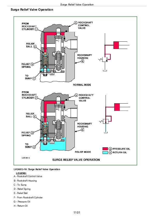
Surge Relief Valve Operation................1101
Rate-of-Drop Valve Operation-Full Open................1103
Rate-of-Drop Valve Operation-Partially Open................1105
Rate-of-Drop Valve Operation-Full Closed................1107
Rockshaft Draft-Sensing Operation................1109
Float Selective Control Valve Operation-Neutral Position................1111
Regenerative Selective Control Valve Operation-Neutral Position................1113
Float Selective Control Valve Operation-Extend Position................1115
Regenerative Selective Control Valve Operation-Extend Position................1117
Float Selective Control Valve Operation-Retract Position................1119
Regenerative Selective Control Valve Operation-Retract Position................1121
Float Selective Control Valve Operation- Float Position................1123
Regenerative Selective Control Valve Operation-Regenerative Position................1125
Quick Disconnect Coupler Operation................1127
Group 15: Diagnosis................1073
Diagnostic Information................1130
Preliminary Hydraulic System Inspection................1131
Hydraulic Oil Warm-Up Procedure................1132
Entire Hydraulic System Fails to Function/No Hydraulic Pump Output................1133
Insufficient Pump Delivery................1134
Hydraulic Functions Too Slow................1135
Excessive Pump Pressure................1136
Slow Hydraulic Pump Response................1137
Excessive Pump Noise During Operation................1138
Rockshaft Does Not Lift or Lifts Slowly................1139
Rockshaft Does Not Lower or Lowers Slowly................1140
Neutral Position Unstable, Rockshaft Drops after Engine Shut Down................1141
SCV Control Lever Does Not Return to Neutral Position-Float SCV................1142
SCV Lever Does Not Remain in Detent Position-Float SCV................1143
SCV Lever Does Not Return to Neutral Position-Regenerative SCV................1144
Remote Cylinder Does Not Extend or Retract................1145
Remote Cylinder Settles Under Load................1146
Remote Cylinder Operates Too Fast or Too Slow................1147
Mid Mount Control Valve Joystick Lever Does Not Return to Neutral Position................1148
Group 16: Hydraulic Tests-Without SCV................1074
Hydraulic System Tests-Without SCV................1150
Pump Flow Test-Without SCV................1151
Main Relief Valve Test-Without SCV................1153
Group 17: Hydraulic Tests-With SCV................1074
Hydraulic System Tests-With SCV................1156
Pump Flow Test-With SCV................1157
Main Relief Valve Test-With SCV................1159
SCV Leakage Test................1161
Group 18: Hydraulic Tests-With Mid Mount Control Valve................1074
Hydraulic System Tests-With Mid Mount Control Valve................1164
Pump Flow Test-With Mid Mount Control Valve................1165
Main Relief Valve Test-With Mid Mount Control Valve................1167
Mid Mount Control Valve Leakage Test................1169
Group 19: Hydraulic Tests-All................1074
Rockshaft Leakage Test................1173
Rockshaft Lift Cycle Test................1175
Group 20: Adjustments................1075
Rockshaft Sensing Lever Friction Adjustment................1178
Rockshaft Position-Sensing Lever Adjustment................1179
Rockshaft Draft-Sensing Lever Adjustment................1181
Mid Mount Control Valve Joystick Cable Adjustment................1183
Group 21: Hydraulic Schematics................1075
Hydraulic Circuit Symbols................1187
Hydraulic Schematic-With Selective Control Valve................1189
Hydraulic Schematic-With Mid Mount Control Valve................1191
Hydraulic Schematic-With Selective Control Valve and Power Beyond Valve................1193
Section 299: Dealer Fabricated Tools................1195
Group 00: Dealer Fabricated Tools................1195
DFLV1A Final Drive Turning Tool................1197
TM1792 - Diagnostics and Repair Technical Manual for John Deere Tractors Models 5105 and 5205


