John Deere 3029, 4039, 4045, 6059, 6068 Engines Component Technical Manual (CTM3274)
Catalog:
Model:
Complete service repair manual with Electrical Wiring Diagrams for John Deere 3029, 4039, 4045, 6059, 6068 Diesel Engines, with all the technical information to maintain, diagnose, repair, and rebuild like professional mechanics.
John Deere 3029, 4039, 4045, 6059, 6068 Engines workshop service repair manual includes:
* Numbered table of contents easy to use so that you can find the information you need fast.
* Detailed sub-steps expand on repair procedure information
* Numbered instructions guide you through every repair procedure step by step.
* Troubleshooting and electrical service procedures are combined with detailed wiring diagrams for ease of use.
* Notes, cautions and warnings throughout each chapter pinpoint critical information.
* Bold figure number help you quickly match illustrations with instructions.
* Detailed illustrations, drawings and photos guide you through every procedure.
* Enlarged inset helps you identify and examine parts in detail.
ctm3274 English - John Deere 3029, 4039, 4045, 6059, 6068 engines (saran) ( -499999cd) Component Technical Manual.pdf
ctm3276 Spanish - Motores Liter Saran ( -499999CD)
ctm3273 German - Motoren (Saran) 3029 4039, 4045 6059, 6068 ( -499999CD)
ctm3275 French - Moteurs litre de Saran ( -499999CD)
ctm3277 Italian - Motori (Saran) 3029, 4039, 4045, 6059, 6068 ( -499999CD)
Total Pages: 621 pages
File Format: PDF (bookmarked, ToC, Searchable, Printable)
Language: English etc..
TABLE OF CONTENTS
Section MISC: Engine Application Chart................23
Group : Engine Application Chart................23
Engine Application Chart................23
Section : Safety................27
Group 00: Safety................27
Handle Fluids Safely-Avoid Fires................40
Prevent Battery Explosions................41
Prepare for Emergencies................42
Prevent Acid Burns................43
Avoid High-Pressure Fluids................45
Wear Protective Clothing................46
Service Machines Safely................47
Work in Ventilated Area................48
Work in Clean Area................49
Remove Paint Before Welding or Heating................50
Avoid Heating Near Pressurized Fluid Lines................51
Illuminate Work Area Safely................52
Use Proper Lifting Equipment................53
Practice Safe Maintenance................54
Use Proper Tools................55
Dispose of Waste Properly................56
Live With Safety................57
Group 01: General Information................556
Engine Identification................59
Engine Plate Information (Earlier Design)................60
Engine Plate Information (Later Design)................62
Repower Engine Plate................63
OEM Engine Option Code Label................64
Engine References................65
Basic Engine Specifications (3029 - 4039 Basic Engine Specifications (3029 - 4039 & 6059){pgNO}27 6059)................66
Basic Engine Specifications (4045 Basic Engine Specifications (4045 & 6068){pgNO}27 6068)................67
Diesel Fuel................68
Diesel Engine Oil................69
Diesel Engine Coolant................70
Metric Bolt and Cap Screw Torque Values................71
Unified Inch Bolt and Cap Screw Torque Values................72
Group 02: Engine Mounting................28
Engine Repair Stand................74
Safety Precautions................75
Engine Lifting Procedure................76
Clean Engine................77
Disconnect Turbocharger Oil Inlet Line................78
Group 03: Engine Rebuild Guide................28
Engine Disassembly Sequence................81
Sealant Application Guidelines................83
Engine Assembly Sequence................84
Group 05: Cylinder Head and Valves................28
Special or Essential Tools................581
Specifications................591
Torques for Hardware................473
Cylinder Head - Exploded View................144
Check Valve Lift................97
Removing Cylinder Head................98
Cleaning Injection Nozzle Bores................99
Valve Actuating Parts................100
Remove Valves and Valve Springs................101
Checking Cylinder Head Flatness................102
Cleaning Valve Seats................103
Cleaning Valve Guides................104
Measure Valve Guides................105
Lapping Valve Seats................106
Check Valve Recess................107
Remove Valve Seat Inserts................108
Valve Seat Insert Installation................110
Check Valves................111
Grind Valves................112
Check Valve Spring Tension................113
Inspect Valve Rotators................114
Install Valves................115
Install Cylinder Head................117
Torque Turn Tightening Method................120
Checking Rocker Arm Shaft................121
Install Rocker Arm Assembly................123
Valve Clearance................124
Valve Adjustment Sequence................125
Install Rocker Arm Cover................127
Final Work................129
Group 10: Cyl. Block, Liners, Pistons & Rods................29
Special or Essential Tools................581
Specifications................591
Torques for Hardware................473
Exploded View................144
Piston and Connecting Rod Removal................145
Cylinder Liner Bore Measure................147
Cylinder Liner Removal................148
Cylinder Liner Deglazing................149
Cylinder Block Cleaning................150
Checking Piston Cooling Jets................151
Cam Follower Bore Measure................152
Camshaft Bore Measure................153
Camshaft Bushing Replacement Tool................154
Remove Camshaft Bushing................156
Installing Camshaft Bushing................157
Crankshaft Bore Measure................158
Crankshaft Bearing Cap Replacement................159
Cylinder Block Top Desk Flatness................160
Balancer Shaft Bore Measure................161
Balancer Shaft Bushing Replacement................162
Oversize Balancer Shaft Bushing Installation................163
Cylinder Liner Protrusion Measure................164
Liner Packing Installation................166
Liner O-Ring Installation................167
Cylinder Liner Installation................168
Connecting Rod Bearing Measure................170
Rod Bearing Clearance................172
Connecting Rod Bushing................173
Connecting Rod Bushing Replacement (Straight Pin-End Conrod Except Small Pin)................174
Connecting Rod Bushing Replacement (Tapered Pin-End Conrod)................175
Measure Piston Pin................178
Piston Cleaning................179
Measure Piston Pin Bore................180
Piston Top Ring Groove................181
Second and Third Piston Ring Grooves................182
Piston Head and Skirt Checking................183
Piston Ring Identification................184
Install Piston Rings................185
Piston Rings Staggering................187
Piston/Liner Set Information................188
Piston and Connecting Rod Assembly................189
Piston and Connecting Rod Installation................190
Torque-Turn Method................192
Piston Protrusion Measure................193
Final Verifications................194
Complete Final Assembly................195
Group 15: Crankshaft, Main Bearings and Flywheel................30
Special or Essential Tools................581
Self-Manufactured Tool Puller for Crankshaft Pulley w/o Threaded Holes................203
Specifications................591
Torques for Hardware................473
Vibration Damper Checking (Engine Without Front PTO)................207
Pulley or Vibration Damper Removal................208
Pulley or Vibration Damper Installation................209
Vibration Damper or Pulley Checking (Engine With Front PTO)................210
Vibration Damper or Pulley Removal (Engine With Front PTO)................212
Vibration Damper or Pulley Installation (Engine With Front PTO)................214
Install Vibration Damper or Pulley (Engine With Crankshaft-Gear-Driven Aux. Drive)................216
Flywheel Removal................217
Flywheel Ring Gear Replacement................218
Ball Bearing Installation................219
Flywheel Installation................220
Crankshaft Wear Sleeve Removal................221
Flywheel Housing Replacement................223
Oil Seal/Wear Sleeve Installation................225
Crankshaft End Play Measure................227
Crankshaft Removal................229
Crankshaft Identification................230
Crankshaft Inspection................231
Journal OD Check................232
Main Bearing Clearance................233
Determine Crankshaft Main Bearing Clearance Using PLASTIGAGEPLASTIGAGE is a trademark of DANA Corp.................31
Crankshaft Regrinding................235
Crankshaft Regrinding Guidelines................236
Micro-Finishing Specifications................591
Crankshaft Gear Replacement................238
Main Bearing Inserts Installation................240
2-Piece Thrust Bearing Installation................241
5/6-Piece Thrust Bearing Installation Standard thrust washer sets for service contain now 4 thrust washers instead of 3 currently installed by the factory and previously included in service sets.................31
Crankshaft Installation................243
Group 20: Camshaft, Balancer Shafts and Timing Gear Train................31
Special or Essential Tools................581
Self-Manufactured Tool Template for Front Plate Replacement................439
Specifications................591
Auxiliary Gear Drive Specifications (37 kW)................254
Torques for Hardware................473
Timing Gear Backlash Measure................256
Camshaft End Play Measure................257
Removing Camshaft................258
Camshaft Journal Measure................259
Measure Height of Cam Lobe................260
Camshaft Gear Replacement................261
Tachometer Pick-Up Pin Removal................262
Fuel Supply Pump Rear Cam Installation................263
Install Camshaft................264
Cam Follower Checking................265
Balancer Shaft Identification (4-Cylinder Engines)................266
Balancer Shaft End Play Measure................267
Balancer Shaft Removal................268
Balancer Shaft Journal Measure................269
Balancer Shaft Gear Replacement................270
Install Balancer Shafts................272
Idler Gear End Play Measure................273
Remove Front Plate................274
Idler Gear Bushing and Shaft Measure................276
Idler Gear Bushing Replacement................277
Remove Idler Shaft................278
Spring Pin Installation (If Equipped)................279
Upper Idler Shaft Installation................280
Lower Idler Shaft Installation................282
Front Plate Gasket................283
Front Plate Installation................285
Upper Timing Gear Train Installation................288
Lower Timing Gear Train Installation................290
Auxiliary Drive Gear Installation (37 kW)................292
Oil Deflector Installation................294
Timing Gear Cover Identification................295
Install Composite Material Timing Gear Cover................296
Install Aluminum Timing Gear Cover................298
Installation of Timing Gear Cover for 37 kW Auxiliary Drive................300
Install Crankshaft Front Oil Seal................301
Install Wear Ring................302
Install Auxiliary Equipment Driven by Camshaft Gear (19 kW Aux. Drive)................303
Crankshaft-Gear-Driven Auxiliary Drive (37 kW)................304
Auxiliary Drive Gear Removal (37 kW)................305
Ball Bearing and Dowel Installation................306
Auxiliary Gear and Shaft Installation (37 kW)................307
Output Shaft Cover Installation................308
Group 25: Lubrication System................557
Special or Essential Tools................581
Specifications................591
Specifications - Machine Model................313
Torques for Hardware................473
Oil Cooler Identification................322
Standard Oil Cooler Removal................323
Standard Oil Cooler Adapter Replacement................325
Standard Oil Cooler/Oil Filter Brackets Replacement................326
Replace Oil Filter Adapter On Engine With Remote Oil Filter................330
High-Flow Oil Cooler Removal................331
Oil Cooler Distributor Base Removal................332
Oil Cooler Distributor Base Repair................333
High-Flow Oil Cooler/Distributor Base Installation................334
Oil Pressure Regulating Valve Removal................336
Oil Pressure Regulating Valve Seat Replacement................337
Oil Pressure Regulating Valve Installation................338
Dipstick Guide Replacement................339
Oil By-Pass Valve Replacement................341
Oil Suction Screen Replacement (On Standard Oil Pump)................343
Oil Suction Screen Replacement (On High-Flow Oil Pump)................344
Oil Pump Identification................345
Standard Oil Pump Removal................346
Gear Axial Clearance (Standard Oil Pump)................347
Gear Radial Clearance (Standard Oil Pump)................348
Standard Oil Pump Specifications................591
Standard Oil Pump Installation................350
High-Flow Oil Pump Removal................354
Gear Axial Clearance (High-Flow Oil Pump)................355
Gear Radial Clearance (High-Flow Oil Pump)................356
High-Flow Oil Pump Specifications................591
High-Flow Oil Pump Installation................359
Oil Pan Installation................361
Group 30: Cooling System................34
Special or Essential Tools................581
Specifications................591
Torques for Hardware................473
Water Pump - Exploded View................372
Water Pump Identification................373
Water Pump Removal................374
Disassemble Water Pump (Standard Model)................375
Water Pump Bearing Shaft Installation................377
Water Pump Seal Installation................378
Water Pump Impeller Installation................379
Install Pulley or Hub................380
Install Water Pump................381
Water Pump With Rotating Assembly - Exploded View................383
Rotating Assembly Removal................385
Disassembling Rotating Assembly................386
Reassembling Rotating Assembly................387
Rotating Assembly Installation................390
Thermostat Test and Replacement................391
Cooling System Deaeration................393
Check Fan/Alternator Belt Tension................394
Install Fan................396
Install Engine Fan Pulley on 2054 and 2254 Combines (With CD6060HZ001 Engines)................398
Coolant Heater Operation (4 and 6 Cyl. Engines)................400
Replacing the Coolant Heater (4 and 6 Cyl. Engines)................401
Coolant Heater Operation (All Engines)................403
Group 35: Air Intake and Exhaust System................35
Specifications................591
Torques for Hardware................473
Intake Manifold Inspection................414
Exhaust Manifold Inspection................415
Turbocharger Removal................416
Radial Bearing End Play Check (GARRETT Turbocharger)................417
Check Radial Bearing Clearance (SCHWITZER Turbocharger)................418
Axial End Play Check................419
Turbocharger Repair................420
Turbocharger Disassembly................421
Turbocharger Reassembly................422
SCHWITZER Turbocharger Model S2A................424
Prelube Turbocharger................426
Turbocharger Installation................427
Turbocharger Break-In................429
Recommendations for Turbocharger Use................430
Group 40: Fuel System................35
Special or Essential Tools................581
Self-Manufactured Tool Template for Front Plate Replacement................439
Self-Manufactured Tool Example of Stationary Pointer for Dynamic Timing................440
Specifications................591
Specifications - Mannheim Tractors................446
Torques for Hardware................473
Rectangular Fuel Filter Element Replacement................475
Replace Round Fuel Filter Element................476
Replace Round Fuel Filter Assembly................479
Fuel Pump Replacement................480
Lucas CAV Fuel Injection Pump Removal................481
Repairs to Fuel Injection Pump................498
Lucas CAV Fuel Injection Pump Installation................484
Lucas CAV Fuel Injection Pump Static Timing................486
STANADYNE DB2 or DB4 Fuel Injection Pump Removal................487
Repairs to Fuel Injection Pump................498
Replace Throttle Lever (STANADYNE)................490
STANADYNE DB2 or DB4 Fuel Injection Pump Installation................491
STANADYNE DB2 or DB4 Fuel Injection Pump Static Timing................493
Engine Front Plate Replacement................494
STANADYNE DM4 Fuel Injection Pump Removal................496
Repairs to Fuel Injection Pump................498
STANADYNE DM4 Fuel Injection Pump Installation and Timing................499
Remove Fuel Supply Pump on MICO In-Line Fuel Injection Pump................501
Test MICO Fuel Supply Pump for Leaks................502
Disassemble MICO Fuel Supply Pump................503
Assemble MICO Fuel Supply Pump................504
Install Fuel Supply Pump On In-Line Fuel Injection Pump................505
Service Injection Pump Overflow Valve (In-Line Injection Pump)................506
Remove MICO In-Line Injection Pump................507
JDG670A Modification................510
Repair MICO In-Line Fuel Injection Pump................511
Install MICO In-Line Fuel Injection Pump................512
Dynamic Timing (All Pump Types)................514
Install Timing Sensor................516
Install Magnetic Probe (For Use Without Stroboscopic Lamp)................517
Install Stationary Pointer (For Use With Stroboscopic Lamp)................519
Timing Sensor and Magnetic Probe Connection................520
Dynamic Timing at Full Load Rated Speed Using Magnetic Probe................522
Dynamic Timing at No-Load................526
Aneroid Replacement................531
Aneroid Field Adjustment................532
Aneroid Workshop Adjustment................533
Fuel Injection Nozzle Removal................535
Clean Fuel Injection Nozzle................536
Fuel Injection Nozzle Test................537
Fuel Injection Nozzle Disassembly................539
Adjust Fuel Injection Nozzle................540
Install Fuel Injection Nozzle................541
Bleed the Fuel System at Fuel Filter................543
Bleed Fuel System (Lucas-CAV)................545
Bleed Fuel System (STANADYNE)................546
Bleed Fuel System (MICO In-Line Injection Pump)................547
Bleed Fuel System at Fuel Injection Nozzles................548
Adjust Engine Speed On Distributor Injection Pump................549
Adjust Engine Speed on MICO In-Line Injection Pump................551
Group 205: Engine System - Operation................37
Engine-Sectional View................554
General Information................556
Lubrication System................557
Cooling System (4-Cylinder Engine)................561
How the 37 kW Auxiliary Drive Works................562
Group 210: Engine System - Diagnosis and Tests................37
Special or Essential Tools................581
Specifications................591
Engine Break-In Instructions................568
Engine Break-In Oil................569
Diagnosing Engine Malfunctions................570
Checking Engine Compression................574
Checking Engine Oil Pressure................575
Measuring Engine Blow-By................576
Using STANADYNE “TIME-TRAC” as Tachometer................577
Inspect Thermostat and Test Opening Temperature................578
Group 215: Air Intake System - Operation and Tests................37
Special or Essential Tools................581
Specifications................591
Turbocharger Operation................583
Turbocharger Boost Pressure Check................584
Diagnosing Turbocharger Malfunctions................585
Air-to-Air Aftercooler Operation................586
Group 220: Fuel System - Operation and Tests................37
Fuel Filter Operation................589
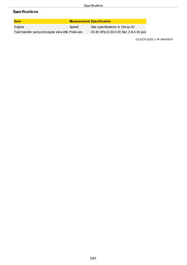
Specifications................591
Fuel System Operation - Distributor Injection Pump................592
Fuel Transfer Pump Operation (Distributor Injection Pump)................594
Lucas CAV Fuel Injection Pump - Sectional View................595
Lucas CAV Fuel Injection Pump - Operation................597
Test Shut-Off Solenoid on Lucas-CAV Injection Pump................599
STANADYNE Fuel Injection Pump (Type DM4) - Sectional View................600
STANADYNE Fuel Injection Pump (DM4) - Operation................601
STANADYNE Fuel Injection Pump (Type DB2/DB4) - Sectional View................602
STANADYNE Fuel Injection Pump (DB2/DB4) - Operation................603
Specifications (In-Line Pump)................604
Fuel System Operation - In-Line Injection Pump (6 Cyl. Shown)................605
Fuel System Operation-In-Line Injection Pump................606
Fuel Transfer Pump Operation (In-Line Injection Pump)................607
Diagnose Fuel Supply Pump Malfunctions-In-Line Injection Pump................609
In-Line Fuel Injection Pump Operation................611
Governor Operation (In-Line Pump)................613
Diagnose In-Line Fuel Injection Pump Malfunctions................615
Fuel Injection Nozzles - General Information................616
Diagnosing Fuel System Malfunctions................618
Testing Fuel Injection Nozzles On a Running Engine................620
Timing of Fuel Injection Pumps On Diesel Engines Using Stroboscopic Lamp................621
John Deere 3029, 4039, 4045, 6059, 6068 Engines Component Technical Manual (CTM3274)


