John Deere Tractors 5200, 5300, 5400, 5500 Diagnostics and Repair Service Manual (TM1520)
Catalog:
Model:
Complete Technical Manual with electrical wiring diagrams for John Deere Tractors 5200, 5300, 5400 and 5500, with all the shop information to maintain, diagnose, repair, and service like professional mechanics (Diagnosis, Operation, Tests, Repair, Service, Troubleshooting).
John Deere 5200, 5300, 5400 and 5500 Tractors workshop technical manual (All Inclusive) includes:
* Numbered table of contents easy to use so that you can find the information you need fast.
* Detailed sub-steps expand on repair procedure information
* Numbered instructions guide you through every repair procedure step by step.
* Troubleshooting and electrical service procedures are combined with detailed wiring diagrams for ease of use.
* Notes, cautions and warnings throughout each chapter pinpoint critical information.
* Bold figure number help you quickly match illustrations with instructions.
* Detailed illustrations, drawings and photos guide you through every procedure.
* Enlarged inset helps you identify and examine parts in detail.
TM1520 English - 5200, 5300, 5400 and 5500 tractors diagnostic and repair Technical Manual.PDF
PRODUCT DETAILS:
Total Pages: 1,783 pages
File Format: PDF (bookmarked, ToC, Searchable, Printable)
Language: English
MAIN SECTIONS
Foreword
John Deere Dealers
General Information
Safety
General Specifications
Fuel and Lubricants
Serial Number Locations
Features and Accessories
Engine Repair
Engine
Cooling System
Fuel and Air Repair
Fuel System
Air Intake System
Speed Control Linkage
Electrical Repair
Battery, Starter and Alternator
Electrical System Components
Wiring Harness
Power Train Repair
Clutch Housing-Collar Shift/TSS Transmission
Clutch Housing-Hydraulic Reverser Transmission
Clutch Assembly-Collar Shift/TSS Transmission
Clutch Assembly-Hydraulic Reverser Transmission
Hydraulic Reverser
Collar Shift/TSS Transmission
Hydraulic Reverser Transmission
Rear PTO Drive Shaft-Collar Shift/TSS Transmission
Rear PTO Drive Shaft-Hydraulic Reverser Transmission
Differential
Final Drives
Mechanical Front Wheel Drive
Creeper Assembly
Steering and Brake Repair
Steering Repair
Brake Repair
Hydraulic Repair
Hydraulic Pump and Filter
Hydraulic Oil Cooler
Rockshaft
Dual Selective Control Valve
Single (Third) Selective Control Valve
Hydraulic Mid Mount Coupler
Hydraulic Power Beyond
Miscellaneous Repair
Front Axle-2WD
Wheels
3-Point Hitch
Operator Station Repair
Seat and Support
ROLL-GARD™
Cab Components
Air Conditioning System
Heating System
Operational Checkout Procedures
Operational Checkout Procedures
Engine Operation, Tests and Adjustments
Component Location
Theory of Operation
Diagnosis, Tests and Adjustments
Fuel/Air Operation, Tests and Adjustments
Component Location
Theory of Operation
Diagnosis, Tests and Adjustments
Electrical System Operation, Tests and Adjustments
Component Location
Theory of Operation
Diagnosis, Tests and Adjustments
Wiring Schematics
Power Train Operation, Tests and Adjustments
Component Location-Collar Shift/TSS Transmission
Component Location-Hydraulic Reverser Transmission
Theory of Operation-Collar Shift/TSS Transmission
Theory of Operation-Hydraulic Reverser Transmission
Diagnosis, Tests and Adjustments-Collar Shift/TSS Transmission
Diagnosis, Tests and Adjustments-Hydraulic Reverser
Steering and Brake Operation, Tests and Adjustments
Component Location
Theory of Operation
Diagnosis, Tests and Adjustments
Hydraulic System Operation, Tests and Adjustments
Component Location
Theory of Operation
Diagnosis
Hydraulic Tests-Without SCV
Hydraulic Tests-With SCV
Hydraulic Tests-All
Adjustments
Hydraulic Schematics
Operator Station
Component Location
Theory of Operation
Diagnosis, Tests and Adjustments
Dealer Fabricated Tools
TABLE OF CONTENTS
Section 10: General Information................32
Group 05: Safety................32
Recognize Safety Information................36
Understand Signal Words................37
Follow Safety Instructions................38
Handle Fluids Safely-Avoid Fires................39
Prevent Battery Explosions................40
Prepare for Emergencies................41
Prevent Acid Burns................42
Service Cooling System Safely................44
Handle Chemical Products Safely................45
Avoid High-Pressure Fluids................46
Park Machine Safely................47
Support Machine Properly................48
Wear Protective Clothing................49
Work in Clean Area................50
Service Machines Safely................51
Work in Ventilated Area................52
Illuminate Work Area Safely................53
Replace Safety Signs................54
Use Proper Lifting Equipment................55
Keep ROPS Installed Properly................56
Service Tires Safely................57
Avoid Harmful Asbestos Dust................58
Avoid Heating Near Pressurized Fluid Lines................59
Remove Paint Before Welding or Heating................60
Use Proper Tools................61
Dispose of Waste Properly................62
Live With Safety................63
Group 10: General Specifications................1754
Machine Specifications-5200 and 5300................67
Travel Speeds-5200 and 5300................70
Machine Specifications-5400 and 5500................72
Travel Speeds-5400 and 5500................75
Service Recommendations for O-Ring Boss Fittings................77
Service Recommendations for Flat Face O-Ring Seal Fittings................79
Metric Cap Screw Torque Values-Grade 7................81
Metric Bolt and Cap Screw Torque Values................82
Unified Inch Bolt and Cap Screw Torque Values................84
Group 20: Fuel and Lubricants................33
Diesel Fuel Specifications................1754
Storing Fuel................90
Do Not Use Galvanized Containers................91
Fill Fuel Tank................92
Diesel Engine Oil................94
Diesel Engine Coolant................96
Liquid Coolant Conditioner................98
Transmission and Hydraulic Oil................99
MFWD Gear Oil................100
Grease (Specific Application)................101
Grease................102
Alternative and Synthetic Lubricants................103
Lubricant Storage................104
Group 25: Serial Number Locations................33
Serial Numbers................106
Product Identification Number Location................107
Engine Serial Number Location................108
Fuel Injection Pump Serial Number Location................109
Alternator Serial Number Location................110
Power Steering Valve Serial Number Location................111
Starter Serial Number Location................112
Transmission Serial Number Location................113
Front Axle (2WD) Serial Number Location................114
Mechanical Front Wheel Drive (MFWD) Serial Number Location................115
Air Conditioning Compressor Serial Number Location................116
Group 30: Features and Accessories................118
Features and Accessories................118
Standard Features-5200, 5300 and 5400................119
Standard Features-5500................121
Factory Installed Optional Equipment................123
Field Installed Optional Kits and Accessories................125
Section 20: Engine Repair................126
Group 05: Engine................126
Service Equipment and Tools................1752
Specifications................1754
Deere Repair-Use CTM8................130
Remove Engine-Tractors without Cab................131
Install Engine-Tractors without Cab................137
Remove Engine-Tractors with Cab................142
Install Engine-Tractors with Cab................148
Group 10: Cooling System................126
Specifications................1754
Engine Water Pump Repair-Use CTM8................155
Remove and Inspect Radiator-5200 through 5400................156
Install Radiator-5200 through 5400................160
Remove and Inspect Radiator-5500 Models................163
Install Radiator-5500 Models................167
Replace Thermostat-Early Models................171
Replace Thermostat-Later Models................173
Section 30: Fuel and Air Repair................175
Group 05: Fuel System................175
Specifications................1754
Injection Pump, Nozzle and Governor Repair-Use CTM8................178
Remove, Inspect and Install Fuel Tank-Without Cab................179
Remove, Inspect and Install Fuel Tank With Cab................183
Replace Fuel Filter-5200, 5300 and 5400................191
Remove and Install Fuel Filter/Primer Pump Assembly-5200, 5300 and 5400................192
Replace Fuel Filter-5500................193
Remove and Install Fuel Filter/Primer Pump Assembly-5500................194
Group 10: Air Intake System................175
Other Material................1753
Specifications................1754
Turbocharger Repair-Use CTM8................198
Remove, Inspect, and Install Air Cleaner Elements-Early Model Tractors................199
Remove, Inspect, and Install Air Cleaner Elements-Later Model Tractors................201
Remove Turbocharger-5400................204
Install Turbocharger-5400................206
Remove Turbocharger-5500................208
Install Turbocharger-5500................211
Turbocharger Break-In................214
Group 15: Speed Control Linkage................175
Inspect and Repair Speed Control Linkage................217
Section 40: Electrical Repair................219
Group 05: Battery, Starter and Alternator................219
Starter Repair-Use CTM77................222
Remove and Install Battery-Without Cab................223
Remove and Install Battery-With Cab................225
Remove and Install Starter-Early Models................227
Remove and Install Starter-Later Models................229
Replace Alternator/Regulator-40 Amp Without Cab................231
Replace Alternator/Regulator-60 Amp Without Cab................232
Group 10: Electrical System Components................219
Service Equipment and Tools................1752
Other Material................1753
Replace Air Filter Restriction Switch................237
Replace Coolant Temperature Sender................238
Replace Engine Speed Sensor................239
Replace Fuel Shut-Off Solenoid................240
Replace Engine Oil Pressure Sender................241
Replace Air Intake Heater................242
Replace Air Intake Heater Relay................243
Replace Key Switch................245
Replace Tractor Light Switch................246
Replace Radio (Optional Equipment)................248
Replace Speakers (Optional Equipment)................249
Replace Antenna (Optional Equipment)................250
Replace Turn Signal Controller................252
Replace Instrument Panel-Collar Shift/TSS Transmission................253
Replace Instrument Panel-Hydraulic Reverser Transmission................256
Replace Rear PTO Switch-Tractors Without Cab................260
Replace Rear PTO Switch-Tractors With Cab................261
Replace Neutral Start Switch................262
Replace Seat Switch................263
Replace Fuel Level Sender-Tractors Without Cab................264
Replace Fuel Level Sender-Tractors With Cab................265
Replace Wiper Control Switch................267
Replace Wiper Motor................269
Replace Blower Control Switch................270
Replace Air Conditioning Temperature Control Switch................272
Replace Dome Light................275
Replace Dome Light Switch................276
Group 15: Wiring Harness................220
Service Equipment and Tools................1752
Service Parts Kits................947
Replace Connector Body-Blade Terminals................281
Replace WEATHER PACK WEATHER PACK is a trademark of Packard Electric Connector................220
Install Weather PackWEATHER PACK WEATHER PACK is a trademark of Packard Electric Contact................220
Replace Front Wiring Harness................286
Replace Rear Wiring Harness: 5200-5400 With Fuse Block Located in Engine Compartment................288
Replace Rear Wiring Harness: 5200-5400 With Fuse Block Located Under Steering Column................291
Replace Rear Wiring Harness-Cab Models................293
Replace Cab Wiring Harness-Lights................295
Replace Cab Wiring Harness-Radio/Antenna................297
Replace Cab Wiring Harness-Main................299
Section 50: Power Train Repair................302
Group 05: Clutch Housing-Collar Shift/TSS Transmission................302
Service Parts Kits................947
Specifications................1754
Separate Engine from Clutch Housing-Tractors Without Cab................332
Install Engine to Clutch Housing-Tractors Without Cab................314
Separate Engine from Clutch Housing-Tractors With Cab................340
Install Engine to Clutch Housing-Tractors With Cab................344
Replace Clutch Housing Seal................326
Inspect and Repair Clutch Pedal and Linkage................348
Group 06: Clutch Housing-Hydraulic Reverser Transmission................302
Specifications................1754
Separate Engine from Clutch Housing-Tractors Without Cab................332
Install Engine to Clutch Housing-(HYD REV) Tractors without Cab................336
Separate Engine from Clutch Housing-Tractors With Cab................340
Install Engine to Clutch Housing-Tractors With Cab................344
Inspect and Repair Clutch Pedal and Linkage................348
Group 10: Clutch Assembly-Collar Shift/TSS Transmission................302
Special or Essential Tools................1751
Other Material................1753
Service Parts Kits................947
Specifications................1754
Remove and Install Clutch Assembly................381
Disassemble and Inspect Clutch Assembly................382
Assemble Clutch Assembly................386
Traction Clutch Finger Adjustment................365
PTO Clutch Finger Adjustment................390
Remove and Inspect Clutch Release Mechanism and Shafts................392
Install Clutch Release Mechanism and Shafts................395
Group 11: Clutch Assembly-Hydraulic Reverser Transmission................302
Special or Essential Tools................1751
Other Material................1753
Service Parts Kits................947
Specifications................1754
Remove and Install Clutch Assembly................381
Disassemble and Inspect Clutch Assembly................382
Assemble Clutch Assembly................386
PTO Clutch Finger Adjustment................390
Remove and Inspect Clutch Release Mechanism and Shafts................392
Install Clutch Release Mechanism and Shafts................395
Remove, Inspect and Repair Transmission Pump................398
Group 12: Hydraulic Reverser................303
Specifications................1754
Remove and Install Hydraulic Reverser Control Valve................402
Disassemble, Inspect and Repair Hydraulic Reverser Control Valve................404
Remove and Install Hydraulic Reverser................413
Disassemble, Inspect and Repair Reverse Idle Gear................418
Disassemble, Inspect and Repair Clutch Gear................420
Disassemble, Inspect and Repair Driven Shaft................422
Disassemble, Inspect and Repair Hydraulic Reverser................424
Group 15: Collar Shift/TSS Transmission................303
Specifications................1754
Separate Clutch Housing from Transmission................502
Install Clutch Housing to Transmission................507
Inspect and Repair Gear Shift Lever................512
Inspect and Repair Range Shift Lever................515
Remove Transmission................517
Disassemble and Inspect Transmission................525
Assemble Transmission................531
Install Transmission................537
Disassemble, Inspect and Assemble Gear Shift Shaft Assemblies................556
Disassemble, Inspect and Assemble Transmission Top Shaft-Collar Shift Transmission................486
Disassemble, Inspect and Assemble Transmission Top Shaft-Top Shaft Synchronized (TSS) Transmission................488
Disassemble, Inspect and Assemble Range Reduction Shaft................561
Disassemble, Inspect and Assemble Driven Shaft................493
Remove, Inspect and Install MFWD and Range Gears................565
Remove, Inspect and Install Reverse Idler Shaft................497
Group 16: Hydraulic Reverser Transmission................304
Service Equipment and Tools................1752
Specifications................1754
Separate Clutch Housing from Transmission................502
Install Clutch Housing to Transmission................507
Inspect and Repair Gear Shift Lever................512
Inspect and Repair Range Shift Lever................515
Remove Transmission................517
Disassemble and Inspect Transmission................525
Assemble Transmission................531
Install Transmission................537
Disassemble, Inspect and Assemble Gear Shift Shaft Assemblies................556
Disassemble, Inspect and Assemble Transmission Bottom Shaft................558
Disassemble, Inspect and Assemble Range Reduction Shaft................561
Disassemble, Inspect and Assemble Top Shaft................563
Remove, Inspect and Install MFWD and Range Gears................565
Remove, Inspect and Replace Hydraulic Reverser Control Lever................567
Group 20: Rear PTO Drive Shaft-Collar Shift/TSS Transmission................304
Specifications................1754
Inspect and Repair Rear PTO Lever and Linkage................582
Remove and Install Rear PTO Drive Shaft Assembly................584
Disassemble, Inspect and Assemble Rear PTO Drive Shaft Assembly................585
Group 21: Rear PTO Drive Shaft-Hydraulic Reverser Transmission................304
Specifications................1754
Inspect and Repair Rear PTO Lever and Linkage................582
Remove and Install Rear PTO Drive Shaft Assembly................584
Disassemble, Inspect and Assemble Rear PTO Drive Shaft Assembly................585
Group 25: Differential................304
Essential Tools................903
Other Material................1753
Service Parts Kits................947
Specifications................1754
Remove and Install Differential Assembly................591
Disassemble, Inspect and Assemble Differential Assembly................593
Remove and Inspect Differential Drive Shaft................595
Install Differential Drive Shaft................598
Differential Cone Point Adjustment................602
Differential Backlash Adjustment................604
Remove, Inspect and Install Differential Lock Assembly................606
Group 30: Final Drives................305
Service Equipment and Tools................1752
Other Material................1753
Specifications................1754
Remove and Install Final Drive Assembly................612
Remove and Inspect Planetary Drive Assembly................614
Install Planetary Drive Assembly................617
Remove, Inspect and Install Axle Shaft Assembly................620
Group 35: Mechanical Front Wheel Drive................305
Special or Essential Tools................1751
Other Material................1753
Specifications................1754
Inspect and Repair MFWD Lever and Linkage................627
Remove and Install MFWD Drop Gearbox................629
Disassemble and Inspect MFWD Drop Gearbox................631
MFWD Drop Gearbox Cross Section................634
Assemble MFWD Drop Gearbox................636
Remove, Inspect and Install MFWD Drive Shaft................641
Remove and Install MFWD Axle Housing Assembly................643
Remove, Inspect and Install MFWD Axle Supports................645
Disassemble and Inspect MFWD Outer Drive................647
Assemble MFWD Outer Drive................650
Remove, Inspect and Install MFWD Swivel Housing................653
Remove, Inspect and Install MFWD Axle Shaft................657
Remove and Install MFWD Differential Carrier Assembly................659
Disassemble and Inspect MFWD Differential Carrier Assembly................661
Assemble MFWD Differential Carrier Assembly................666
Adjust Swivel Pin Bearing Preload-Early Models Only................677
Group 40: Creeper Assembly................306
Other Material................1753
Specifications................1754
Remove and Install Creeper Assembly................682
Disassemble, Inspect and Assemble Creeper Assembly (Early Models)................685
Disassemble, Inspect and Assemble Creeper Assembly (Later Models)................687
Section 60: Steering and Brake Repair................689
Group 05: Steering Repair................689
Service Equipment and Tools................1752
Other Material................1753
Specifications................1754
Service Parts Kits................947
Remove and Install Steering Column and Valve................695
Disassemble and Inspect Steering Valve................697
Assemble Steering Valve................701
Remove and Install Steering Cylinder-2WD Axle................706
Disassemble, Inspect and Assemble Steering Cylinder-2WD Axle................707
Remove and Install Steering Cylinder-MFWD Axle................709
Disassemble, Inspect and Assemble Steering Cylinder-MFWD Axle................711
Remove, Inspect and Install Tie Rod Assembly-2WD Axle................712
Remove, Inspect and Install Tie Rod Assembly-MFWD Axle................714
Inspect and Replace Steering Hydraulic Lines-Without Oil Cooler................716
Inspect and Replace Steering Hydraulic Lines-With Oil Cooler................718
Group 10: Brake Repair................689
Other Material................1753
Specifications................1754
Remove and Install Brake Valve and Pedals................723
Disassemble and Inspect Brake Valve................725
Brake Valve Cross Section................728
Assemble Brake Valve................730
Remove and Inspect Brakes (Early Model Tractors)................733
Install Brakes (Early Model Tractors)................735
Remove and Inspect Brakes (Later Model Tractors)................737
Install Brakes (Later Model Tractors)................740
Inspect and Replace Brake Hydraulic Lines................743
Section 70: Hydraulic Repair................746
Group 05: Hydraulic Pump and Filter................746
Specifications................1754
Remove Inspect and Install Hydraulic Oil Pick-Up Screen................750
Remove and Install Hydraulic Pump-5200, 5300 and 5400................752
Remove Hydraulic Pump External Components-5200, 5300 and 5400................754
Disassemble and Inspect Hydraulic Pump-5200, 5300 and 5400................756
Assemble Hydraulic Pump-5200, 5300 and 5400................759
Install Hydraulic Pump External Components-5200, 5300 and 5400................761
Remove and Install Hydraulic Pump-5500................763
Remove Hydraulic Pump External Components-5500................765
Disassemble and Inspect Hydraulic Pump-5500................767
Assemble Hydraulic Pump-5500................770
Install Hydraulic Pump External Components-5500................772
Remove and Install Hydraulic Filter/Manifold-Early Model................774
Remove and Install Hydraulic Filter/Manifold-Later Model................775
Inspect and Replace Hydraulic Supply/Return Lines................776
Group 06: Hydraulic Oil Cooler................746
Remove, Inspect and Install Hydraulic Oil Cooler................779
Group 10: Rockshaft................746
Other Material................1753
Specifications................1754
Service Parts Kits................947
Inspect and Repair Rockshaft Control Lever Assembly................784
Inspect and Repair Rockshaft Control Linkage................789
Inspect and Repair Draft Sensing Support Assembly................793
Replace Main Relief Valve................795
Replace Rockshaft Surge Relief Valve................797
Remove, Inspect and Install Rate-of-Drop Valve................798
Replace Rockshaft Control Valve................800
Remove and Install Rockshaft Case................803
Remove, Inspect and Install Rockshaft Lift Arms................805
Remove, Inspect and Install Rockshaft Piston and Cylinder................807
Group 15: Dual Selective Control Valve................747
Other Material................1753
Specifications................1754
Service Parts Kits................947
Inspect and Repair Joystick and Linkage-Early Model................813
Inspect and Repair Joystick and Linkage-Later Models................817
Inspect and Repair Joystick and Linkage-Tractors With Cab................820
Remove and Install Dual Selective Control Valve (SCV)................824
Disassemble, Inspect and Assemble Dual Selective Control Valve (SCV)................827
Inspect and Replace Hydraulic Hoses-Dual Selective Control Valve (SCV)................831
Group 16: Single (Third) Selective Control Valve................747
Other Material................1753
Specifications................1754
Service Parts Kits................947
Inspect and Repair Lever and Linkage................837
Remove and Install Single/Third Selective Control Valve (SCV)................839
Disassemble, Inspect and Assemble Single (Third) Selective Control Valve (SCV)................841
Inspect and Replace Hydraulic Hoses-Single (Third) Selective Control Valve................843
Group 20: Hydraulic Mid Mount Coupler................747
Inspect and Replace Hydraulic Hoses-Mid Mount Coupler Without Cab................847
Inspect and Replace Hydraulic Hoses-Mid Mount Coupler With Cab................849
Group 25: Hydraulic Power Beyond................747
Inspect and Replace Power Beyond Hydraulic Lines and Fittings................856
Inspect Power Beyond Motor Control Lines and Fittings................861
Section 80: Miscellaneous Repair................862
Group 05: Front Axle-2WD................862
Specifications................1754
Remove and Install Front Axle-2WD................865
Inspect and Replace Pivot Pin and Bushings-2WD Axle................868
Remove and Install Spindle Assembly-2WD Axle................869
Inspect and Replace Spindle Shaft Bushings-2WD Axle................871
Group 10: Wheels................862
Specifications................1754
Inspect and Replace Front Wheel Bearings................874
Group 15: 3-Point Hitch................862
Specifications................1754
Inspect and Repair Fixed Draft Links................878
Inspect and Repair Telescoping Draft Links................879
Inspect and Repair Lift Link................881
Inspect and Repair Adjustable Lift Link................883
Inspect and Repair Center Link................885
Remove and Install Draw Bar and Support................887
Section 90: Operator Station Repair................889
Group 05: Seat and Support................889
Specifications................1754
Remove and Install Seat and Support-Tractors Without Cab................893
Remove and Install Seat, Support and Base Plate-Tractors With Cab................894
Group 10: ROLL-GARDROLL-GARD is a trademark of Deere & Company.................889
Specifications................1754
Remove and Install ROLL-GARD ROLL-GARD is a trademark of Deere & Company.................889
Group 15: Cab Components................889
Essential Tools................903
Specifications................1754
Remove, Inspect and Install Cab Interior Recirculating Air Filter................905
Remove, Inspect and Install Exterior Cab Intake Air Filter................907
Remove and Install Front Headliner................908
Remove and Install Rear Headliner................910
Remove and Install Lower Front Windows................912
Remove and Install Windowpanes................915
Remove and Install Rear Window................916
Remove and Install Cab Doors................918
Remove and Install Cab Roof................921
Remove and Install Control Console and Support Plate................923
Remove Cab and Floor Plates................926
Install Cab and Floor Plates................936
Group 20: Air Conditioning System................889
Service Equipment and Tools................1752
Specifications................1754
Service Parts Kits................947
Hose and Tubing O-Ring Connection Torques................948
Recover/Recycle Air Conditioning Refrigerant................949
Replace Air Conditioning Receiver-Dryer................1744
Remove, Inspect and Install Air Conditioning Condenser................1743
Remove, Inspect and Install Air Conditioning Compressor................1742
Test Volumetric Efficiency of Compressor................1742
Test Compressor Shaft Seal Leakage................962
Disassemble and Assemble Compressor Clutch................964
Disassemble, Inspect, and Assemble Compressor................1742
Check Compressor Clutch Hub Clearance................969
Inspect Compressor Manifold................970
Remove and Install Compressor Relief Valve................971
Remove Evaporator/Heater Core Housing................972
Install Evaporator/Heater Core Housing................976
Remove Blower Motors................980
Remove Evaporator/Heater Core................982
Leak Test Evaporator/Heater Core................984
Install Evaporator/Heater Core................985
Service Expansion Valve................1745
Expansion Valve Bench Test-Diagram................988
Expansion Valve Bench Test................990
Refrigerant Oil Information................991
Check Compressor Oil Charge................992
Determine Correct Refrigerant Oil Charge................993
Add Refrigerant Oil to System................995
System Information................996
Flush Air Conditioning System................997
Evacuate Air Conditioning System................1000
Charge Air Conditioning System................1002
Group 25: Heating System................890
Replace Heater Temperature Control and Cable................1010
Remove, Test and Install Heater Control Valve................1019
Leak Test Heater Control Valve................1018
Install Heater Control Valve................1019
Section 210: Operational Checkout Procedures................1020
Group 10: Operational Checkout Procedures................1020
Specifications................1754
Operational Checkout Procedure Information................1024
Engine Oil Level and Condition Check................1025
Coolant Level and Condition Check................1026
Transmission and Hydraulic Oil Check................1027
Fan and Belt Check................1028
Compressor Belt Check................1029
Fuel System Check................1030
Air Intake System Check................1032
Electrical System Check................1034
Hydraulic System Check................1036
MFWD Oil Check................1037
Indicator Lamps Check................1038
Cab Blower Motor Check................1039
A/C Compressor Clutch Check................1048
Engine Start Check................1041
Transmission Neutral Start Check................1042
PTO Neutral Start Check................1043
Engine Fast and Slow Idle Operation................1044
Power Steering Check................1045
Differential Lock Check................1046
PTO Engagement Check................1047
Clutch Check................1048
Transmission Shift Check................1049
Range Lever Shift Check................1050
MFWD Drive Check................1051
Brake Check................1052
Rockshaft Check................1053
Selective Control Valve Check................1055
A/C System Operational Check................1057
Cab Heater Valve Check................1058
Miscellaneous Checks................1059
Section 220: Engine Operation, Tests and Adjustments................1060
Group 05: Component Location................1060
Component Location Information................1619
Engine External Components-Left-Hand Side................1064
Engine External Components-Right-Hand Side................1066
Group 10: Theory of Operation................1060
Theory of Operation Information................1625
Engine Lubrication System Operation................1070
Engine Cooling System Operation................1074
Group 15: Diagnosis, Tests and Adjustments................1060
Diagnostic Information................1672
Engine Turns Over but Will Not Start or Starts Hard................1078
Engine Runs Irregularly or Stalls Frequently................1079
Engine Runs Rough................1080
Engine Has Low Power................1081
Engine Smokes-Black or Grey................1083
Engine Smokes Excessively-White................1084
Engine Uses Excess Fuel................1085
Engine Has Excess Noise or Vibration................1086
Engine Uses Excess Oil or Smokes Blue................1087
Engine Has Low Oil Pressure................1088
Engine Coolant Operating Temperature Incorrect................1089
Oil In Coolant or Coolant in Oil................1091
Radiator Bubble Test................1092
Cooling System Test................1094
Radiator Cap Pressure Test................1095
Engine Oil Pressure Test................1096
Cylinder Compression Pressure Test................1098
Fuel Shut-Off Solenoid Check................1100
Throttle Lever Adjustment................1101
Slow Idle Adjustment................1102
Fast Idle Adjustment................1104
Injection Pump Timing Adjustment................1106
Injection Pump Timing Adjustment-New Front Plate Installed................1107
Valve Clearance Adjustment................1110
Fan/Alternator Drive Belt Adjustment................1114
Compressor Drive Belt Adjustment................1116
Turbocharger Boost Pressure Test-5400 and 5500................1118
Bleed Fuel System-3-Cylinder Engine................1120
Bleed Fuel System-4-Cylinder Engine................1122
Section 230: Fuel/Air Operation, Tests and Adjustments................1124
Group 05: Component Location................1124
Component Location Information................1619
Fuel System Components................1127
Air Intake System Components-5200 and 5300................1129
Air Intake System Components-5400 and 5500................1130
Group 10: Theory of Operation................1124
Theory of Operation Information................1625
Fuel System Operation................1133
Fuel Filter/Priming Pump Operation................1135
Fuel Injection Pump Operation................1137
Fuel Injection Nozzle Operation................1140
Air Intake System Operation-5200 and 5300................1142
Air Intake System Operation-5400 and 5500................1144
Turbocharger Operation-5400 and 5500................1146
Group 15: Diagnosis, Tests and Adjustments................1124
Diagnostic Information................1672
Fuel/Air Diagnosis, Tests and Adjustments................1149
Section 240: Electrical System Operation, Tests and Adjustments................1150
Group 05: Component Location................1150
Component Location Information................1619
Engine Electrical Components................1156
Dash Electrical Components................1157
Machine Electrical Components-5200-5400 Without Cab................1159
Machine Electrical Components-5500 Without Cab................1161
Machine Electrical Components-5200-5500 With Cab................1163
Cab Control Panel and Electrical Components................1165
Group 10: Theory of Operation................1150
Theory of Operation Information................1625
Fuse Block and Fuses-Early Models................1169
Fuse Block and Fuses-Later Models................1171
Fuse Block and Fuses-Cab Tractors................1173
Cab Fuse Block and Fuses................1175
Relays................1177
Starting System Operation-Normal................1178
Starting System Operation-Bypass Attempt................1180
Manifold Heater System Operation................1182
Charging System Operation................1184
Lighting System Operation-Turn Signals................1186
Lighting System Operation-Warning Lights................1188
Lighting System Operation-Tail Light................1190
Lighting System Operation-Headlights and Instrument Lights................1192
Instrument Panel System Operation-Tachometer................1194
Instrument Panel System Operation-Fuel Gauge................1196
Instrument Panel System Operation-Temperature Gauge................1198
Instrument Panel System Operation-Hourmeter................1200
PTO Warning System Operation................1202
Air Filter Restriction Indicator Operation................1204
Rear Work Light Operation-Tractors Without Cab................1206
Optional Horn Operation................1208
Optional Accessory Relay and Trailer Connector Operation................1209
Flood Light Operation-Tractors With Cab................1211
Blower Motor Operation-Tractors With Cab................1213
A/C Compressor Operation-Cab Tractors Only................1216
Front Wiper/Washer Operation-Cab Tractors Only................1219
Rear Wiper/Washer Operation-Cab Tractors Only................1221
Dome Light Operation-Cab Tractors Only................1223
Group 15: Diagnosis, Tests and Adjustments................1151
Diagnostic Information................1672
Wire Color Chart................1227
Starting System Test Points-Normal Operation................1229
Starting System Test Points-Bypass Attempt................1233
Manifold Heater Test Points................1237
Charging System Test Points................1240
Lighting System Test Points-Turn Signals (Tractors Without Cab)................1244
Lighting System Test Points-Turn Signals (Tractors With Cab)................1248
Lighting System Test Points-Warning Lights (All Tractors)................1253
Lighting System Test Points-Rear Work Light (Tractors Without Cab)................1256
Lighting System Test Points-Flood Lights (Tractors With Cab)................1259
Lighting System Test Points-Tail Light (Tractors Without Cab)................1264
Lighting System Test Points-Tail Lights (Tractors With Cab)................1267
Lighting System Test Points-Headlights and Instrument Lights................1270
Lighting System Test Points-Dome Light (Tractors With Cab)................1275
Instrument Panel System Test Points-Tachometer................1278
Instrument Panel System Test Points-Fuel Gauge................1282
Instrument Panel System Test Points-Temperature Gauge................1285
Instrument Panel System Test Points-Hourmeter................1289
Instrument Panel System Test Points-Oil Pressure................1293
PTO Warning System Test Points................1297
Air Filter Restriction Test Points................1301
Optional Horn Test Points................1304
Optional Accessory Relay and Trailer Connector Test Points................1307
Blower Motor Test Points (Tractors With Cab)................1311
A/C Compressor Clutch Coil Test Points (Tractors With Cab)................1316
Front Wiper/Washer Test Points (Tractors With Cab)................1319
Rear Wiper/Washer Test Points (Tractors With Cab)................1323
Battery Voltage and Specific Gravity Tests................1326
Charge Battery................1328
Battery Load Test................1330
Starter AMP Draw/RPM Test................1332
Starter No-Load Amp Draw/RPM Test................1334
Alternator/Regulator Test................1336
Starter Solenoid Test................1338
Starter Relay Test................1339
Key Switch Test................1341
Plug-In Relay Test................1343
Diode Pack Test................1345
Fuse Test................1347
Neutral Start Switch Test................1348
PTO Switch Test................1349
PTO Seat Switch Test................1350
Light Switch Test................1351
Turn Signal Controller Test................1353
Fuel Shut-Off Solenoid Test................1354
Blower Switch Test................1355
Blower Motor Resistors Test................1357
A/C Thermostatic Control Switch Test................1359
Front Wiper/Washer Switch Test................1360
Rear Wiper/Washer Switch Test................1362
Door Switch Test................1363
Dome Light Switch Test................1364
Group 20: Wiring Schematics................1152
Schematic Information................1366
Component Identification Table................1367
Electrical Schematic-Early 5200-5400 Models (Without Cab)................1369
Electrical Schematic (Optional Equipment)-Early 5200-5400 Models (Without Cab)................1371
Electrical Schematic-Later 5200-5400 and All 5500 Models (Without Cab)................1373
Electrical Schematic (Optional Equipment)-Later 5200-5400 and All 5500 Models (Without Cab)................1375
Electrical Schematic-Later 5200-5400 Models and All 5500 (With Cab)................1381
Electrical Schematic-Later 5200-5400 Models and All 5500 (With Cab)................1381
Section 250: Power Train Operation, Tests and Adjustments................1385
Group 05: Component Location-Collar Shift/TSS Transmission................1385
Component Location Information................1619
Power Train Components................1391
Clutch Components................1393
Transmission Components-Collar Shift................1395
Transmission Components-Top Shaft Synchronized (TSS)................1397
Final Drive Components................1411
Rear PTO Components................1412
Group 06: Component Location-Hydraulic Reverser Transmission................1385
Component Location Information................1619
Power Train Components-Hydraulic Reverser Transmission................1403
Clutch Components-Hydraulic Reverser Transmission................1405
Hydraulic Reverser Components................1407
Transmission Components-Hydraulic Reverser Transmission................1409
Final Drive Components................1411
Rear PTO Components................1412
Group 10: Theory of Operation-Collar Shift/TSS Transmission................1385
Theory of Operation Information................1625
Clutch Operation................1415
Transmission Lubrication System................1476
Transmission Power Flow-Gear Shift (Collar)................1424
Transmission Power Flow-Gear Shift (TSS)................1426
TSS Transmission Synchronizer Operation-Reverse and 2nd Gear (Disk-and-Plate- Type Synchronizer)................1428
TSS Transmission Synchronizer Operation-1st and 3rd Gear (Cone-Type Synchronizer)................1430
Transmission Power Flow-Range Shift................1473
Rear PTO Operation................1478
Differential Power Flow................1437
Differential Lock Operation................1439
Final Drive Operation................1479
Mechanical Front Wheel Drive (MFWD) Operation................1443
Group 11: Theory of Operation-Hydraulic Reverser Transmission................1385
Theory of Operation Information................1625
Clutch Operation-PTO Clutch Engaged (Hydraulic Reverser Transmission)................1447
Clutch Operation-PTO Clutch Disengaged (Hydraulic Reverser Transmission)................1449
Hydraulic Reverser General Information................1451
Hydraulic Reverser Operation in Forward................1452
Hydraulic Reverser Operation in Reverse................1454
Hydraulic Reverser Power Flow................1456
Hydraulic Reverser Control Valve Operation-Initial Engine Start-Up, Clutch Pedal Up................1458
Hydraulic Reverser Control Valve Operation-F-N-R Lever in Neutral, Clutch Pedal Down................1460
Hydraulic Control Valve Operation-F-N-R Lever in Neutral, Clutch Pedal Up................1462
Hydraulic Control Valve Operation-F-N-R Lever in Forward, Clutch Pedal Up................1464
Hydraulic Control Valve Operation-F-N-R Lever in Reverse, Clutch Pedal Up................1467
Transmission Power Flow-Gear Shift................1469
Gear Shift Synchronizer Operation................1471
Transmission Power Flow-Range Shift................1473
Transmission Lubrication System................1476
Rear PTO Operation................1478
Final Drive Operation................1479
Differential Operation................1480
MFWD Operation................1481
Group 15: Diagnosis, Tests and Adjustments-Collar Shift/TSS Transmission................1386
Diagnostic Information................1672
Isolate the Problem Area................1523
Traction Clutch Slips................1486
Traction Clutch Dragging................1487
Traction Clutch Does Not Engage................1488
Traction Clutch Grabs................1489
Traction Clutch Squeaks................1490
Traction Clutch Does Not Release................1491
Traction Clutch Chatters................1492
Traction Clutch Rattles................1493
Traction Clutch Engagement is Noisy................1494
Excessive Vibration in Traction Clutch................1495
Clutch Pedal Does Not Return................1527
Clutch Pedal Loose................1497
Clutch Pedal Pulsates................1498
Jerky or Rough Transmission of Power................1499
Low Transmission Oil Level (Excessive Oil Leakage)................1526
Gears Clash, Shift Hard, or Will Not Engage................1531
Two Speeds Engage Together................1532
Transmission Will Not Stay In Gear................1503
Transmission Noisy................1534
PTO Noisy................1505
PTO Hard to Engage................1506
PTO Will Not Operate................1507
PTO Will Not Stay Engaged................1508
Excessive Differential Noise................1509
Differential Does Not Work................1510
No Differential Lock................1511
Differential Chatters................1512
Axle Noise................1513
Axle Shaft Will Not Turn................1514
MFWD Lever is Hard to Engage................1515
MFWD Lever Will Not Stay In “ON” Position................1516
Noisy Front Wheel Drive Operation................1517
Clutch Pedal Free Play Adjustment................1518
PTO Clutch Lever Adjustment................1519
Group 16: Diagnosis, Tests and Adjustments-Hydraulic Reverser................1387
Diagnostic Information................1672
Isolate the Problem Area................1523
Low Transmission Oil Level (Excessive Oil Leakage)................1526
Clutch Pedal Does Not Return................1527
Tractor Does Not Move in Forward or Reverse................1528
Hydraulic Reverser Engages Too Quickly or Too Slowly................1529
Hydraulic Reverser Does Not Disengage................1530
Gears Clash, Shift Hard, or Will Not Engage................1531
Two Speeds Engage Together................1532
Transmission Will Not Stay in Gear................1533
Transmission Noisy................1534
PTO Troubleshooting................1535
Differential Troubleshooting................1536
Axle Troubleshooting................1537
MFWD Troubleshooting................1538
Hydraulic Control Valve Tests................1539
Transmission Pump Flow Test................1545
Adjust Forward-Neutral-Reverse Cable................1547
Clutch Pedal Linkage Adjustment................1554
Park Brake Cable Adjustment................1556
Section 260: Steering and Brake Operation, Tests and Adjustments................1559
Group 05: Component Location................1559
Component Location Information................1619
Steering System Components-5200, 5300 and 5400 Without Cab................1563
Steering System Components-5500 and All Cab Units................1573
Brake System Components-Early Models................1567
Brake System Components-Later Models................1569
Group 10: Theory of Operation................1559
Theory of Operation Information................1625
Steering System Components-5500 and All Cab Units................1573
Steering System Operation-5200, 5300 and 5400 Without Cab................1575
Steering System Operation-5500 and All Cab Units................1577
Steering Valve Operation-Neutral and Manual Turning................1579
Steering Valve Operation-Power Turning................1581
Brake System Operation-Early Models................1583
Brake System Operation-Later Models................1585
Brake Valve Operation................1587
Group 15: Diagnosis, Tests and Adjustments................1559
Diagnostic Information................1672
Isolate the Problem-Steering System................1593
Steering Sluggish or Loss of Steering................1594
Isolate the Problem-Brakes................1595
Excessive Brake Pedal Leak-Down................1596
Excessive Brake Chatter................1597
Steering Pump Flow Test................1598
Steering Valve Relief Test................1600
Steering Cylinder Leakage Test................1602
Steering Valve Leakage Test................1603
Toe-In Check and Adjustment-Standard Axle................1605
Toe-In Check and Adjustment-MFWD................1607
MFWD Steering Stop Adjustment................1609
Brake Pedal Adjustment................1610
Adjust Brake Drag................1612
Bleed Brake System................1614
Section 270: Hydraulic System Operation, Tests and Adjustments................1615
Group 05: Component Location................1615
Component Location Information................1619
Hydraulic System Components................1675
Selective Control Valve Components................1622
Group 10: Theory of Operation................1615
Theory of Operation Information................1625
Hydraulic System Operation................1626
Hydraulic Filter Operation-Early Model................1629
Hydraulic Filter Operation-Later Model................1631
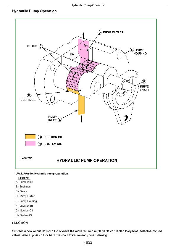
Hydraulic Pump Operation................1633
Rockshaft Control Valve Operation (Early Models)-Flow Regulator Valve................1635
Rockshaft Control Valve Operation (Early Models)-Neutral Position................1637
Rockshaft Control Valve Operation (Early Models)-Raise Position................1639
Rockshaft Control Valve Operation (Early Models)-Lowering Position................1641
Rockshaft Control Valve Operation (Later Models)-Two Flow Regulator Valves................1643
Rockshaft Control Valve Operation (Later Models)-Neutral Position................1645
Rockshaft Control Valve Operation (Later Models)-Raise Position................1647
Rockshaft Control Valve Operation (Later Models)-Lower Position................1649
Surge Relief Valve Operation................1651
Main Relief Valve Operation................1653
Rate-of-Drop Valve Operation-Full Open................1655
Rate-of-Drop Valve Operation-Full Closed................1657
Rockshaft Draft-Sensing Operation................1659
Selective Control Valve Operation-Neutral Position................1661
Selective Control Valve Operation-Extend and Retract Positions................1663
Selective Control Valve Operation-Boom Spool Float Position................1665
Selective Control Valve Operation-Bucket Spool Regenerative Position................1667
Double-Acting Sleeve Coupler Operation................1669
Group 15: Diagnosis................1615
Diagnostic Information................1672
Preliminary Hydraulic System Inspection................1673
Hydraulic Oil Warm-Up Procedure................1674
Hydraulic System Components................1675
Entire Hydraulic System Fails to Function/No Hydraulic Pump Output................1677
Insufficient Pump Delivery................1678
Hydraulic Functions Too Slow................1679
Excessive Pump Pressure................1680
Slow Hydraulic Pump Response................1681
Excessive Pump Noise During Operation................1682
Rockshaft Does Not Lift or Lifts Slowly................1683
Rockshaft Does Not Lower or Lowers Slowly................1684
Neutral Position Unstable, Rockshaft Drops After Engine Shut-Down................1685
SCV Control Lever Does Not Return to Neutral Position-Single (Third) SCV................1686
SCV Joystick Does Not Return to Neutral Position-Dual SCV................1687
SCV Joystick Does Not Remain In Detent Position-Dual SCV................1688
Remote Cylinder Does Not Extend or Retract................1689
Remote Cylinder Settles Under Load................1690
Remote Cylinder Operates Too Fast or Too Slow................1691
Group 16: Hydraulic Tests-Without SCV................1616
Hydraulic System Tests-Without SCV................1694
Pump Flow Test-Without SCV................1696
Main Relief Valve Test-Without SCV................1698
Group 17: Hydraulic Tests-With SCV................1616
Hydraulic System Tests-With SCV................1702
Pump Flow Test-With SCV................1704
Main Relief Valve Test-With SCV................1706
SCV Leakage Test................1707
Group 18: Hydraulic Tests-All................1616
Rockshaft Leakage Test................1711
Rockshaft Lift Cycle Test................1713
Group 19: Adjustments................1616
Rockshaft Control Lever Friction Adjustment................1716
Rockshaft Position-Sensing Feedback Linkage Adjustment................1717
Rockshaft Draft-Sensing Feedback Linkage Adjustment................1721
Main Relief Valve Adjustment................1723
Group 20: Hydraulic Schematics................1617
Hydraulic Circuit Symbols................1726
Hydraulic Schematic-Without Selective Control Valve................1728
Hydraulic Schematic-With Selective Control Valve................1730
Section 290: Operator Station................1732
Group 05: Component Location................1732
Air Conditioning System Components................1735
Group 10: Theory of Operation................1732
Refrigerant R134a................1738
Air Conditioning System Air Flow................1739
Air Conditioning System Cycle................1741
Air Conditioning System Cycle................1741
Compressor................1742
Condenser................1743
Receiver-Dryer................1744
Expansion Valve................1745
A/C Temperature Control Switch................1746
Evaporator................1747
Heater Temperature Control Knob................1748
High and Low Pressure Switches................1749
Group 15: Diagnosis, Tests and Adjustments................1732
Special or Essential Tools................1751
Service Equipment and Tools................1752
Other Material................1753
Specifications................1754
Adjust Heater Temperature Control Cable................1782
Section 299: Dealer Fabricated Tools................1784
Group 00: Dealer Fabricated Tools................1784
JDG826-PTO Clutch Finger Height Gauge................1786
JDG827-Traction Clutch Finger Height Gauge................1787
JDG828-Traction Clutch Finger Height Adjustment Tool................1788
JDG919-PTO Clutch Finger Height Gauge-Hydraulic Reverser................1789
DFLV1A Final Drive Turning Tool................1790
DFRW83-Nozzle Assembly................1791
DFRW20-Compressor Holding Fixture................1793
John Deere Tractors 5200, 5300, 5400, 5500 Diagnostics and Repair Service Manual (TM1520)


