CTM370 - Component Technical Manual for John Deere 6135 Diesel Engine Level 15 ECU
Catalog:
Model:
Complete Component Technical Manual with Electrical Wiring Diagrams for John Deere 6135 Diesel Engine — Level 15 ECU, with all the technical information to maintain, diagnose, repair, and rebuild like professional mechanics.
John Deere 6135 Diesel Engine — Level 15 ECU workshop service repair manual includes:
* Numbered table of contents easy to use so that you can find the information you need fast.
* Detailed sub-steps expand on repair procedure information
* Numbered instructions guide you through every repair procedure step by step.
* Troubleshooting and electrical service procedures are combined with detailed wiring diagrams for ease of use.
* Notes, cautions and warnings throughout each chapter pinpoint critical information.
* Bold figure number help you quickly match illustrations with instructions.
* Detailed illustrations, drawings and photos guide you through every procedure.
* Enlarged inset helps you identify and examine parts in detail.
CTM370 English - John Deere 6135 Diesel Engine — Level 15 ECU - (Worldwide Edition) Component Technical Manual (CTM).pdf
ctm371 Spanish - Motor diésel 6135 — ECU Nivel 15 -: (Edición mundial)
ctm372 French - Moteur diesel 6135—Contrôleur ECU niveau 15 -: (Édition mondiale)
ctm373 German - Dieselmotor 6135 — ECU (Level 15) -: (Weltweite Ausgabe)
ctm374 - Motore diesel 6135 – ECU livello 15 -: (Edizione universale)
ctm377 Russian - Дизельный двигатель 6135 — БУД уровня 15 -: (Исполнение для всех стран)
ctm378 Portuguese - 6135 Motor a Diesel — Nível 15 ECU -: (Edição Mundial)
ctm380 Chinese - 6135 柴油发动机 — 15 级 ECU -: (世界通用机型)
PRODUCT DETAILS:
Total Pages: 1,963 pages
File Format: PDF (bookmarked, ToC, Searchable, Printable, high quality)
Language: English
TABLE OF CONTENTS
Section 01: General Information................164
Group 000: Safety................22
Avoid Heating Near Pressurized Fluid Lines................26
Avoid High-Pressure Fluids................27
Avoid Hot Exhaust................28
Avoid Static Electricity Risk When Refueling................29
Construct Dealer-Made Tools Safely................31
Decommissioning — Proper Recycling and Disposal of Fluids and Components................32
Follow Safety Instructions................33
Handle Agricultural Chemicals Safely................34
Handle Fluids Safely—Avoid Fires................36
Handling Batteries Safely................37
Illuminate Work Area Safely................39
Install All Guards................40
Live With Safety................41
Park Machine Safely................42
Practice Safe Maintenance................43
Precautions for Welding................236
Prepare for Emergencies................47
Prevent Acid Burns................48
Prevent Battery Explosions................50
Prevent Machine Runaway................51
Protect Against High Pressure Spray................52
Protect Against Noise................53
Recognize Safety Information................54
Remove Paint Before Welding or Heating................55
Replace Safety Signs................56
Service Cooling System Safely................57
Service Machines Safely................58
Stay Clear of Rotating Drivelines................59
Support Machine Properly................60
Understand Signal Words................61
Use Proper Lifting Equipment................62
Use Proper Tools................63
Use Steps and Handholds Correctly................64
Wait Before Opening High-Pressure Fuel System................65
Wear Protective Clothing................66
Work in Clean Area................67
Work In Ventilated Area................68
Group 001: Engine Identification................23
Engine Serial Number Plate Information................72
OEM Engine Option Code Label................75
Information Relative to Emissions Regulations................76
Emissions Control System Certification Label................77
Group 002: Fuels, Lubricants and Coolants................23
Diesel Fuel................80
Diesel Fuel Additive Products................82
BioDiesel Fuel................83
Minimizing the Effect of Cold Weather on Diesel Engines................85
Handling and Storing Diesel Fuel................87
Lubricity of Diesel Fuel................88
Testing Diesel Fuel................89
Engine Oil and Filter Service Intervals................90
Diesel Engine Oil — Tier 3 and Stage III................91
Diesel Engine Break-In Oil — Non-Emissions Certified and Certified Tier 1, Tier 2, Tier 3, Stage I, Stage II, and Stage III................93
Oil Filters................95
Oilscan™ and CoolScan™................96
Grease................97
Alternative and Synthetic Lubricants................98
Lubricant Storage................99
Mixing of Lubricants................100
Diesel Engine Coolant (engine with wet sleeve cylinder liners)................101
Supplemental Coolant Additives................103
Operating in Warm Temperature Climates................104
Additional Information About Diesel Engine Coolants and John Deere LIQUID COOLANT CONDITIONER................105
Diesel Engine Coolant................107
Testing Diesel Engine Coolant................108
Drain Intervals for Diesel Engine Coolant................109
Group 003: Fuel System Identification................24
13.5L Fuel Supply System Identification................24
Section 02: Repair and Adjustments................116
Group 90: Fuel System Repair and Adjustment — Type 1 Fuel Supply System................116
General Information................164
Fuel System Components................121
Install Primary Filter Assembly................123
Install Secondary (Final) Filter Assembly................126
Fuel Filter/Water Separator Assembly................128
Replacing Fuel Filter/Water Separator................134
Replacing Fuel Filter/Water Separator................134
Remove and Install Low Pressure Regulating Valve................138
Remove and Install High Pressure Regulating Valve................140
Remove and Install 100 Micron Internal Filter Housing Screen Insert................142
Remove and Install Fuel Filter Check Valve................144
Remove and Install Primer Pump................145
Remove and Install High Pressure Fuel Pump................186
Remove Electronic Unit Injector................189
Install Electronic Unit Injectors (EUI) - Type 1 Fuel Supply System................150
Install Injector Wiring Harness................192
Adjust Electronic Unit Injector Preload................194
Bleed Fuel System................195
Clean Electronic Injector Bore................197
Clean Electronic Injector Orifice................198
Clean Electronic Injector Body................199
Inspect Electronic Injector Body................200
Clean Electronic injectors (In Engine)................201
Group 91: Fuel System Repair and Adjustment — Type 2 Fuel Supply System................116
About This Group................589
General Information................164
Fuel System Components - Dual Filter, Right Hand Side................165
Fuel System Components - Dual Filter, Left Hand Side................167
Dual Fuel Filter Assembly................168
Install Fittings into Cylinder Head................171
Assemble and Install Fuel Filter Head Bracket................172
Install Jumper Harness to Fuel Filter Header Assembly................174
Install Fuel Filter Assembly and Fuel Lines................175
Replace Fittings on Fuel Filter Assembly................181
Remove and Install High Pressure Fuel Regulator Valve................183
Remove and Install Fuel Return Regulator Valve................184
Remove and Install Fuel Filter Screen................185
Remove and Install High Pressure Fuel Pump................186
Remove Electronic Unit Injector................189
Install Electronic Unit Injectors (EUI) - Type 2 Fuel Supply System................190
Install Injector Wiring Harness................192
Adjust Electronic Unit Injector Preload................194
Bleed Fuel System................195
Clean Electronic Injector Bore................197
Clean Electronic Injector Orifice................198
Clean Electronic Injector Body................199
Inspect Electronic Injector Body................200
Clean Electronic injectors (In Engine)................201
Group 100: Electronic Air System Repair and Adjustment................117
Remove, Inspect, and Install EGR Valve (Tier 3/Stage IIIA)................205
Remove, Inspect, and Install EGR Cooler................207
Remove and Install Variable Geometry Turbocharger Actuator................209
Remove and Install Actuator Linkage................211
Remove Turbocharger................215
Install Turbocharger................216
Group 110: Electrical Component Repair and Adjustment-Type 1 Fuel Supply System................117
Engine Control Unit (ECU) Maintenance................219
Remove and Install Engine Control Unit (ECU)................220
Remove and Install Coolant Temperature Sensor................222
Remove and Install Fuel Temperature Sensor - Type 1 Fuel Supply System................223
Remove and Install Fuel Pressure Sensor................224
Remove and Install Water-in-Fuel (WIF) Sensor - Type 1 Fuel Supply System................225
Remove and Install Oil Pressure Sensor................358
Remove and Install Manifold Air Temperature (MAT) Sensor................227
Remove and Install Manifold Absolute Pressure (MAP) Sensor................228
Remove and Install Exhaust Gas Recirculation (EGR) Exhaust Temperature Sensor................348
Remove and Install Charge Air Cooler Outlet Temperature Sensor................230
Remove and Install Compressor Inlet Temperature Sensor................231
Remove and Install Cam Position Sensor................361
Remove and Install Crank Position Sensor................360
Remove and Install Turbo Speed Sensor................362
Welding................236
Using High-Pressure Washing................237
Connectors................238
Connector Repair................239
Installation of Repair Wire Assembly (RWA)................240
Repair WEATHERPACK Connector................249
Repair METRI-PACK Connectors (Push Type)................252
Repair DT Series DEUTSCH Connectors................255
Repair HD Series DEUTSCH Connectors................259
Repair Cinch FlexBox Connector................263
Group 115: Electrical Component Repair and Adjustment-Type 2 Fuel Supply System................118
Remove and Install Electric Low Pressure Fuel Pump................272
Remove and Install Fuel Temperature Sensor - Type 2 Fuel Supply System................274
Remove and Install High Pressure Fuel Sensor................275
Remove and Install Low Pressure Fuel Sensor................276
Remove and Install Water-in-Fuel (WIF) Sensor - Type 2 Fuel Supply System................277
Section 03: Theory of Operation................278
Group 130: Electronic Fuel System Operation................278
About This Group................589
Type 1 Fuel Supply System Operation................283
Type 2 Fuel Supply System Operation................285
Type 2 Fuel Supply System Fuel Filter Header Assembly................289
Type 2 Fuel Supply System Electric Low Pressure Fuel Pump................292
Type 2 Fuel Supply System Right Side Option................295
Type 2 Fuel Supply System Left Side Option................297
Type 2 Fuel Supply System Fuel Filters and Water Separator................299
Type 2 Fuel Supply System Fuel Return................301
Electronic Unit Injector (EUI) Operation................305
Group 135: Air System Operation................278
About This Group................589
Intake and Exhaust System Operation, non-EGR engines................311
Turbocharger Operation................312
Turbocharger Actuator Operation................314
Exhaust Gas Recirculator (EGR) Exhaust Gas Recirculator (EGR) & Variable Geometry Turbocharger (VGT) Operation{pgNO}278 Variable Geometry Turbocharger (VGT) Operation................316
Group 140: Electrical Control System Operation................278
About This Group................589
Electronic Control System Terminology................323
Component Location Diagram 1................326
Component Location Diagram 2................327
Component Location Diagram 3................328
Component Location Diagram 4................329
Component Location Diagram 5................331
Component Location Diagram 6................333
Component Location Diagram 7................334
Component Location Diagram 8................335
Component Location Diagram 9................336
Component Location Diagram 10................337
Engine Control Unit (ECU) System Operation................338
Controller Area Network (CAN)................341
Pilot Injection Operation................342
Monitoring Engine Parameters................343
Measuring Temperature................344
Engine Control Unit (ECU) Temperature Sensor................345
Engine Coolant Temperature (ECT) Sensor................346
Fuel Temperature Sensor................347
Exhaust Gas Recirculation (EGR) Exhaust Temperature Sensor................348
Charge Air Cooler Outlet Air Temperature Sensor................349
Intake Manifold Air Temperature (MAT) Sensor................350
Turbo Turbine Inlet Temperature................351
Turbo Compressor Inlet Temperature Sensor................352
Measuring Pressure................353
Barometric Air Pressure (BAP) Sensor................354
High-Pressure Fuel Pressure Sensor................355
Fuel Transfer Pump Pressure Sensor................356
Manifold Air Pressure (MAP) Sensor................357
Oil Pressure Sensor................358
Measuring Speed................359
Crank Position Sensor................360
Cam Position Sensor................361
Turbo Speed Sensor................362
Throttle Descriptions................363
CAN Throttle................364
Pulse-Width-Modulated (PWM) Throttle................365
Analog Throttle................366
Digital Multi-State Throttle................367
Dual-State Throttle................368
Tri-State Throttle................369
Ramp Throttle................370
Throttle Adjustments................372
Throttle Offsets................373
Self-Calibration................374
Combination Throttle................375
Marine Throttle................377
Engine Derate and Shutdown Protection................379
Electronic Unit Injector (EUI) Wiring Harness Connector................381
Torque Curve Selection................382
Governor Droop Mode Selection................383
Water in Fuel (WIF) Sensor................384
Engine Coolant Level Switch................385
Cruise Control Operation................386
Power Supply #2................387
Power Supply #3................388
Power Supply #4................389
Power Supply #5................390
Section 04: Diagnostics................391
Group 150: Observable Diagnostics and Tests With Type 1 Fuel Supply System................391
About this Group................483
E1 - Engine Cranks but Won't Start (Type 1 Fuel Supply System)................391
E2 - Engine Misfires/Runs Irregularly (Type 1 Fuel Supply System)................391
E3 - Engine Does Not Develop Full Power (Type 1 Fuel Supply System)................391
E4 - Engine Emits Excessive White Exhaust Smoke (Type 1 Fuel Supply System)................391
E5 - Engine Emits Excessive Black or Gray Exhaust Smoke (Type 1 Fuel Supply System)................391
F1 - Type 1 Fuel Supply System Check................391
F2 - Excessive Fuel Filter Replacement................456
Check Fuel Supply Quality (Type 1 Fuel Supply System)................459
Test for Air in Fuel (Type 1 Fuel Supply System)................461
Check Fuel Supply Pressure................463
Bleed Fuel System (Type 1 Fuel Supply System)................464
Restarting Engine That Has Run Out Of Fuel (Type 1 Fuel Supply System)................465
Excessive Engine Crankcase Pressure (Blow-By)................391
Exhaust Gas Recirculation (EGR) System Diagnostic................391
Variable Geometry Turbocharger (VGT) Component Test (Type 1 Fuel Supply System)................391
Group 155: Observable Diagnostics and Tests With Type 2 Fuel Supply System................391
About this Group................483
E1 - Engine Cranks but Won't Start (Type 2 Fuel Supply System)................391
E2 - Engine Misfires/Runs Irregularly (Type 2 Fuel Supply System)................391
E3 - Engine Does Not Develop Full Power (Type 2 Fuel Supply System)................391
E4 - Engine Emits Excessive White Exhaust Smoke (Type 2 Fuel Supply System)................391
E5 - Engine Emits Excessive Black or Gray Exhaust Smoke (Type 2 Fuel Supply System)................391
E8 - Primary Analog Throttle Does Not Respond................391
E9 - Secondary Analog Throttle Does Not Respond................391
F1 - Type 2 Fuel Supply System Check................391
Check Fuel Supply Quality (Type 2 Fuel Supply System)................569
Test for Air in Fuel (Type 2 Fuel Supply System)................571
Bleed Fuel System (Type 2 Fuel Supply System)................573
Type 2 Fuel Return To Tank System Check................391
Restarting Engine That Has Run Out Of Fuel (Type 2 Fuel Supply System)................579
Charge Air System................392
Variable Geometry Turbocharger (VGT) Component Test (Type 2 Fuel Supply System)................392
Group 160: Trouble Code Diagnostics and Tests................392
About This Group................589
Communication Error Test Instructions................590
Connecting to Service ADVISOR................591
Control Unit Information and Overview Test................593
Cylinder Cutout Test Instructions................595
Cylinder Cutout Test Using JDG1250................1784
Cylinder Electronic Compression Test Instructions................600
Cylinder Misfire Test Instructions................605
Diagnostic Gauge Data Parameters Viewing Instructions................607
Diagnostic Gauge Active DTC Viewing Instructions................610
Diagnostic Gauge Stored DTC Viewing Instructions................612
Diagnostic Gauge Stored DTC Clearing Instructions................614
Diagnostic Trouble Code Designations................616
Diagnostic Trouble Codes List................620
Digital Multimeter — Using................625
EGR Valve — Clean Test Instructions................627
Electrical Circuit Concepts................629
Electronic Injector — Calibration Information................635
Engine Control Unit (ECU) — Level Identification................637
Engine Control Unit (ECU) — Donating this Engine’s ECU to be Used Elsewhere................638
Engine Control Unit (ECU) — Replacing Current ECU with Another ECU................642
Engine Control Unit (ECU) — Replacing Current ECU with Another ECU — Cannot Communicate with Current ECU................644
Engine Control Unit (ECU) — Reprogramming Current ECU................646
Engine Control Unit (ECU) — Reprogramming Instructions................647
Engine Hours — Updating Instructions................649
EGR Valve — Learn Value Reset Instructions................651
Harness Diagnostic Mode Test................652
Interactive Tests and Calibration Results — Printing, Exporting, or Saving Instruction................654
Intermittent DTC Diagnostics................655
Internal Data Monitor — Instructions................656
Keep Electronic Control Unit Connectors Clean................661
Load Profile Information Test — Instructions................662
Service ADVISOR Data Parameter Description................666
Snapshot Instructions................673
Software and Hardware Verification................674
Terminal Test................393
Trim Options Information................681
VGT Actuator Travel Range Test................682
VGT — Learn Value Reset Instructions................684
000028.03 - Digital Throttle Signal Out of Range High................393
000028.04 - Digital Throttle Signal Out of Range Low................393
000029.03 - Secondary Analog Throttle Signal Out of Range High................393
000029.04 - Secondary Analog Throttle Signal Out of Range Low................393
000091.03 - Primary Analog Throttle Signal Out of Range High................393
000091.04 - Primary Analog Throttle Signal Out of Range Low................393
000091.09 - Throttle CAN Message Missing................393
000094.03 - Low Pressure Fuel Signal Out of Range High................393
000094.04 - Low Pressure Fuel Signal Out of Range Low................393
000094.17 - Low Pressure Fuel Signal Slightly Low................393
000097.03 - Water In Fuel Signal Out of Range High................393
000097.04 - Water In Fuel Signal Out of Range Low................393
000097.16 - Water in Fuel Detected................393
000100.01 - Engine Oil Pressure Signal Extremely Low................393
000100.04 - Engine Oil Pressure Signal Out of Range Low................393
000100.18 - Engine Oil Pressure Signal Moderately Low................393
000100.31 - Engine Oil Pressure Detected with Engine Stopped................393
000102.02 - Manifold Air Pressure Signal Invalid................393
000102.03 - Manifold Air Pressure Signal Out of Range High................393
000102.04 - Manifold Air Pressure Signal Out of Range Low................393
000103.00 - Turbo Speed Extremely High................393
000103.05 - Turbo Speed Signal Circuit has High Resistance................393
000103.08 - Turbo Speed Signal Invalid................393
000103.31 - Turbo Speed Signal Missing................394
000105.00 - Manifold Air Temperature Signal Extremely High................394
000105.03 - Manifold Air Temperature Signal Out of Range High................394
000105.04 - Manifold Air Temperature Signal Out of Range Low................394
000105.15 - Manifold Air Temperature Signal Slightly High................394
000105.16 - Manifold Air Temperature Signal Moderately High................394
000107.00 - Air Filter Restriction Switch Activated................394
000107.31 - Air Filter Restriction Switch Activated................394
000108.02 - Barometric Air Pressure Signal Invalid................394
000110.00 - Coolant Temperature Signal Extremely High................394
000110.03 - Coolant Temperature Signal Out of Range High................394
000110.04 - Coolant Temperature Signal Out of Range Low................394
000110.15 - Coolant Temperature Signal Slightly High................394
000110.16 - Coolant Temperature Signal Moderately High................394
000110.17 - Coolant Temperature Signal Slightly Low................394
000111.01 - Coolant Level Extremely Low................394
000157.01 - High Pressure Fuel Signal Extremely Low................394
000157.03 - High Pressure Fuel Signal Out of Range High................394
000157.04 - High Pressure Fuel Signal Out of Range Low................394
000157.16 - High Pressure Fuel Signal Moderately High................394
000157.18 - High Pressure Fuel Signal Moderately Low................394
000158.17 - ECU Power Down Error................394
000174.00 - Fuel Temperature Signal Extremely High................394
000174.03 - Fuel Temperature Signal Out of Range High................394
000174.04 - Fuel Temperature Signal Out of Range Low................394
000174.16 - Fuel Temperature Signal Moderately High................394
000189.00 - Engine Speed Derate Condition Exists................394
000190.00 - Engine Speed Extremely High................394
000190.01 - Engine Extremely Overloaded................394
000190.16 - Engine Speed Moderately High................394
000190.18 - Engine Moderately Overloaded................394
000237.02 - VIN Security Data Invalid................394
000237.13 - VIN Option Code Security Data Conflict................394
000237.31 - VIN Security Data Missing................395
000412.00 - EGR Temperature Signal Extremely High................395
000412.03 - EGR Temperature Signal Out of Range High................395
000412.04 - EGR Temperature Signal Out of Range Low................395
000412.15 - EGR Temperature Signal Slightly High................395
000412.16 - EGR Temperature Signal Moderately High................395
000441.03 - Gear Oil Temperature Signal Out of Range High................395
000441.04 - Gear Oil Temperature Signal Out of Range Low................395
000611.03 - Injector Shorted to Voltage Source................395
000611.04 - Injector Shorted to Ground................395
000627.01 - All Injector Circuits Have High Resistance................395
000627.18 - Injector Power Supply Voltage Moderately Low................395
000629.12 - ECU EEPROM Error................395
000629.13 - ECU Boot Block Error................395
000636.02 - Camshaft Position Signal Invalid................395
000636.05 - Camshaft Position Circuit Has High Resistance................395
000636.06 - Camshaft Position Circuit Has Low Resistance................395
000636.08 - Camshaft Position Signal Missing................395
000636.10 - Camshaft Position Signal Rate of Change Abnormal................395
000637.02 - Crankshaft Position Signal Invalid................395
000637.05 - Crankshaft Position Circuit Has High Resistance................395
000637.06 - Crankshaft Position Circuit Has Low Resistance................395
000637.07 - Crankshaft and Camshaft Position Signals Out of Sync................395
000637.08 - Crankshaft Position Signal Missing................395
000637.10 - Crankshaft Position Signal Rate of Change Abnormal................395
000640.11 - External Engine Protection Commanded................395
000640.31 - External Derate Commanded................395
000641.04 - VGT Actuator Supply Voltage Out of Range Low................395
000641.12 - VGT Actuator Communication Error................395
000641.13 - VGT Actuator Learn Error................395
000641.16 - VGT Actuator Temperature Moderately High................395
000647.05 - Engine Fan Drive Circuit Has High Resistance................395
000647.07 - Engine Fan Drive Not Responding................395
000651.05 - Injector #1 Circuit Has High Resistance................396
000651.06 - Injector #1 Circuit Has Low Resistance................396
000651.13 - Injector #1 Calibration Fault................396
000652.05 - Injector #2 Circuit Has High Resistance................396
000652.06 - Injector #2 Circuit Has Low Resistance................396
000652.13 - Injector #2 Calibration Fault................396
000653.05 - Injector #3 Circuit Has High Resistance................396
000653.06 - Injector #3 Circuit Has Low Resistance................396
000653.13 - Injector #3 Calibration Fault................396
000654.05 - Injector #4 Circuit Has High Resistance................396
000654.06 - Injector #4 Circuit Has Low Resistance................396
000654.13 - Injector #4 Calibration Fault................396
000655.05 - Injector #5 Circuit Has High Resistance................396
000655.06 - Injector #5 Circuit Has Low Resistance................396
000655.13 - Injector #5 Calibration Fault................396
000656.05 - Injector #6 Circuit Has High Resistance................396
000656.06 - Injector #6 Circuit Has Low Resistance................396
000656.13 - Injector #6 Calibration Fault................396
000898.09 - Engine Speed CAN Message Invalid................396
000970.31 - External Shutdown Switch Activated................396
000971.31 - External Derate Switch Activated................396
001075.12 - Low Pressure Fuel Pump Status Error................396
001109.31 - Approaching Engine Protection Shutdown................396
001110.31 - Engine Protection Shutdown Active................396
001136.00 - ECU Temperature Signal Extremely High................396
001136.16 - ECU Temperature Signal Moderately High................396
001172.03 - Turbo Compressor Inlet Temperature Signal Out of Range High................396
001172.04 - Turbo Compressor Inlet Temperature Signal Out of Range Low................396
001180.00 - Calculated Turbo Turbine Inlet Temperature Signal Extremely High................396
001180.16 - Calculated Turbo Turbine Inlet Temperature Moderately High................396
001568.02 - Torque Curve Selection CAN Message Error................396
001569.31 - Engine in Power Derate Condition................396
001639.01 - Fan Speed Signal Extremely Low................396
001639.16 - Fan Speed Signal Moderately High................397
001639.18 - Fan Speed Signal Moderately Low................397
002000.13 - Incorrect ECU for Application................397
002005.09 - No CAN Message From Source Address 5................397
002005.14 - Incorrect CAN Message Received From Source Address 5................397
002030.09 - No CAN Message From Source Address 30................397
002071.09 - No CAN Message From Source Address 71................397
002630.00 - Charge Air Cooler Outlet Temperature Signal Extremely High................397
002630.03 - Charge Air Cooler Outlet Temperature Signal Out Of Range High................397
002630.04 - Charge Air Cooler Outlet Temperature Signal Out of Range Low................397
002630.15 - Charge Air Cooler Outlet Temperature Signal Slightly High................397
002630.16 - Charge Air Cooler Outlet Temperature Signal Moderately High................397
002659.02 - Calculated EGR Flow Rate Invalid................397
002659.15 - Calculated EGR Flow Rate Slightly High................397
002659.17 - Calculated EGR Flow Rate Slightly Low................397
002790.16 - Calculated Compressor Outlet Temperature Moderately High................397
002791.02 - EGR Valve Position Signal Invalid (Forward)................397
002791.03 - EGR Valve Position Signal Out of Range High (Forward)................397
002791.04 - EGR Valve Position Signal Out of Range Low (Forward)................397
002791.07 - EGR Valve Not Reaching Expected Position (Forward)................397
002791.13 - EGR Valve Calibration Change Over a Short Period of Time (Forward)................397
002791.31 - EGR Valve Calibration Change Over a Long Period of Time (Forward)................397
002795.07 - VGT Actuator Not Reaching Expected Position................397
003510.03 - Sensor Supply #2 Voltage Out of Range High................397
003510.04 - Sensor Supply #2 Voltage Out of Range Low................397
003511.03 - Sensor Supply #3 Voltage Out of Range High................397
003511.04 - Sensor Supply #3 Voltage Out of Range Low................397
003512.03 - Sensor Supply #4 Voltage Out of Range High................397
003512.04 - Sensor Supply #4 Voltage Out of Range Low................397
003513.03 - Sensor Supply #5 Voltage Out of Range High................397
003513.04 - Sensor Supply #5 Voltage Out of Range Low................397
003822.02 - EGR Valve Position Signal Invalid (Rear)................397
003822.03 - EGR Valve Position Signal Out of Range High (Rear)................397
003822.04 - EGR Valve Position Signal Out of Range Low (Rear)................398
003822.07 - EGR Valve Not Reaching Expected Position (Rear)................398
003822.13 - EGR Valve Calibration Change Over a Short Period of Time (Rear)................398
003822.31 - EGR Valve Calibration Change Over a Long Period of Time (Rear)................398
200852.31 - A/C Compressor State Incorrect................398
516598.00 - Engine Overload Condition Exists – Most Severe Level................398
516598.16 - Engine Overload Condition Exists – Moderately Severe Level................398
523379.03 - Single Point Ground #7 Has High Resistance................398
523744.31 - A/C Compressor is ON When It Should be OFF................398
Group 165: Common Observables................398
E6 - Engine Will Not Crank................398
E7 - Abnormal Engine Noise................398
E10 - Engine Idles Poorly................398
E11 - Turbo Surge................398
F3 - Excessive Fuel Consumption................398
F4 - Fuel in Oil................398
D1 - ECU Does Not Communicate with Service ADVISOR................398
D2 - ECU Does Not Communicate with Diagnostic Gauge or Gauge Displays CAN Bus Error................398
D3 - ECU Does Not Program with Service ADVISOR................398
Temperature Sensor Validity Test................398
EGR/VGT Temperature and Flow Test................398
Section 05: Tools and Other Materials................1800
Group 170: Special Tools................1769
D17030BR................1771
JDG145................1772
JDG359................1773
JDG360................1774
JDG361................1775
JDG362................1776
JDG363................1777
JDG364................1778
JDG783................1779
JDG785................1780
JDG820................1781
JDG865................1782
JDG998................1783
JDG1250................1784
JDG1334................1785
JDG1725................1786
JDG1744................1787
JDG1869................1788
JDG10194................1789
JDG10466................1790
JDG11072................1791
JDG11263................1792
JDG11409................1794
JT03513C................1795
JT05536................1796
JT07195B................1797
JT07306................1798
Group 180: Lubricants, Sealants, and Other Materials................1800
Other Materials................1800
Section 06: Wiring Harnesses and Schematics................1801
Group 190: Wiring Harness Information................1801
ECU Wiring Harness Routing................1804
Remove and Install Engine Wire Harness................1805
13.5L Wire Splice Location Diagrams................1801
Redundant ECU Option 13.5L Wire Splice Location Diagram................1828
Group 191: Wiring Harness Information — Marine................1801
Marine Harness Type Identification................1831
Electrical System Layout — Marine Type A................1832
Engine Wiring Harness Routing — Marine Type B................1837
ECU Wiring Harness Routing — Marine Type B................1840
Main and Remote Station Wiring Harness Routing — Marine Type B................1843
Remove and Install Engine Wiring Harness — Marine Type B................1847
Group 195: Electrical Schematics................1801
13.5L 12V ECU Wiring Diagram 1................1801
13.5L 12V ECU Wiring Diagram 2................1801
13.5L 12V ECU Wiring Diagram 3................1801
13.5L 12V ECU Wiring Diagram 4................1801
13.5L 12V ECU Wiring Diagram 5................1801
13.5L 12V ECU Wiring Diagram 6................1801
13.5L 12V ECU Wiring Diagram 7................1801
13.5L 12V ECU Wiring Diagram 8................1801
13.5L 24V ECU Wiring Diagram 1................1801
13.5L 24V ECU Wiring Diagram 2................1801
13.5L 24V ECU Wiring Diagram 3................1801
13.5L 24V ECU Wiring Diagram 4................1801
13.5L 24V ECU Wiring Diagram 5................1801
13.5L 24V ECU Wiring Diagram 6................1801
13.5L 24V ECU Wiring Diagram 7................1801
13.5L 24V ECU Wiring Diagram 8................1801
OEM Engines - Instrument Panel/Engine Start Components Electrical Wiring Diagram................1880
OEM Instrument Panel / Engine Start Components Electrical Wiring Diagram - Continued................1884
Oil Temperature Switch Option................1885
Redundant ECU Option 13.5L Wiring Diagram................1886
Group 196: Electrical Schematics — Marine................1802
Marine Schematic Type Identification................1892
13.5L Wiring Diagram 1 — Marine Type A................1802
13.5L Wiring Diagram 2 — Marine Type A................1802
13.5L Wiring Diagram 3 — Marine Type A................1802
13.5L Wiring Diagram 4 — Marine Type A................1802
13.5L Wiring Diagram 5 — Marine Type A................1802
Transition Harness Wiring Diagram 1 — Marine Type A................1900
Transition Harness Wiring Diagram 2 — Marine Type A................1902
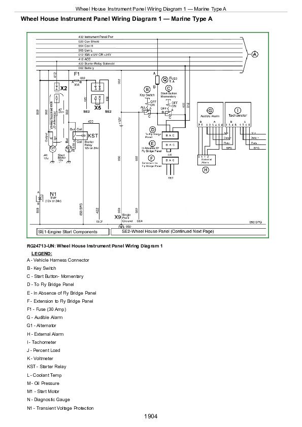
Wheel House Instrument Panel Wiring Diagram 1 — Marine Type A................1904
Wheel House Instrument Panel Wiring Diagram 2 — Marine Type A................1906
Fly Bridge Instrument Panel Wiring Diagram — Marine Type A................1908
Engine Schematic — Marine Type B................1910
ECU Schematic — Marine Type B................1912
Main and Remote Station Schematic — Marine Type B................1918
Section 07: Specifications................1920
Group 200: Repair Specifications................1920
Unified Inch Bolt and Cap Screw Torque Values................1923
Metric Bolt and Cap Screw Torque Values................1925
General OEM Engine Specifications................1926
Electronic Air System Repair and Adjustment Specifications................1927
Fuel System with Type 1 Fuel Supply System Repair and Adjustment Specifications................1928
Fuel System with Type 2 Fuel Supply System Repair and Adjustment Specifications................1929
Electronic Engine Control System Specifications With Type 1 Fuel Supply System................1930
Electrical Engine Control System Specifications With Type 2 Fuel Supply System................1931
Group 210: Diagnostic Specifications................1920
Application Specifications................1933
OEM Engines - Derate Specifications................1934
EGR Temperature Sensor Characteristics................1936
Compressor Inlet Temperature Sensor Characteristics................1937
Manifold Air Temperature and Charge Air Cooler Outlet Temperature Characteristics................1938
Barometric Pressure Versus Altitude................1939
CTM370 - Component Technical Manual for John Deere 6135 Diesel Engine Level 15 ECU


