John Deere Combines 9780 CTS (S.N. 000001-072799) Diagnostics & Repair Service Manual (TM4635)
Catalog:
Model:
Complete Diagnosis and Repair Service manual including Electrical Wiring Diagrams for John Deere Combines 9780 CTS (S.N. XXXXXX - 072799), with all the shop information to maintain, diagnose, repair, and rebuild.
John Deere 9780 CTS Combines (S.N. 000001-072799) workshop Diagnosis and Repair manual includes:
* Numbered table of contents easy to use so that you can find the information you need fast.
* Detailed sub-steps expand on repair procedure information
* Numbered instructions guide you through every repair procedure step by step.
* Troubleshooting and electrical service procedures are combined with detailed wiring diagrams for ease of use.
* Notes, cautions and warnings throughout each chapter pinpoint critical information.
* Bold figure number help you quickly match illustrations with instructions.
* Detailed illustrations, drawings and photos guide you through every procedure.
* Enlarged inset helps you identify and examine parts in detail.
TM4635 - John Deere Combines 9780 CTS (S.N. 000001-072799) Technical Manual (Diagnosis and Repair).PDF
tm4634 German - CTS Mahdrescher (070231- ) und CTS 9780
tm4636 French - Moissonneuses-batteuses CTS (070231- ) et CTS 9780
tm4638 Italian - Mietitrebbie CTS
Total Pages: 3,923 pages
File Format: PDF (bookmarked, ToC, Searchable, Printable, high quality)
Language: English
MAIN SECTIONS
Foreword
General
Safety
Identification Number Location
Specifications
Engine
Remove and Install Engine
Cooling System
Lower Engine Component Repair
Fuel and Air Intake System Repair
Air Intake System
Diesel Fuel System
Electrical System
Components
Bulbs and Switches
Batteries
Harness and Connector Repair
Gauges and Monitors
Wiper and Radio
Alternator
Starting Motor
Electronic Engine Control
Power Train Repair
Engine Gearcase and Valve
Transmission and Differential
Ring and Pinion Final Drive
Hydrostatic System
Cam Lobe Motor
Power Steering and Brakes
Steering
Brakes
Hydraulic System Repair
Hydraulic Reservoir
Hydraulic Pumps
Hydraulic Valves
Hydraulic Cylinders
Motors
Accumulator
Reel Pump Drive
Separator Shell
Gull Wing Doors
Cleaning Fan Shields
Operator`s Station Repair
Air Conditioning System (R134a)
System Components
Cab
Feeder House Repair
Feeder House/Conveyor
Feeder House Conveyor Drum
Conveyor Shaft and Slip Clutch
Feeder House Drives and Reverser Gear Case
Automatic Header Control Tilt Cylinder
Automatic Header Control Tilt Frame
Separator Repair
Beaters
Cylinder Drives
Tine Separator Module
Tine Separators
Engine Gearbox to Module Drives
Tine Separator Gearboxes
Shoe Supply Augers, Chaffer and Sieve Frame
Tailings Elevator and Augers
Primary Countershaft Gearcase
Header Electromagnetic Clutch
Grain Tank and Unloading System
Grain Tank Cross Augers
Unloading Auger System Drives
Vertical Unloading Auger and Lower Gearcase
Horizontal Unloading Auger and Gearcase
Upper Clean Grain Elevator
Grain Tank and Extensions
Clean Grain Elevator and Loading Auger Gearcase
Chaff Spreader
Chaff Spreader
Engine Operation and Tests
Cooling System and Rotary Screen Operation
6081 Engine Operation - Bosch
Fuel/Air Operation and Tests
Air Intake System
Fuel System
Electrical System
General Information
Functional Schematic and Harness Diagrams
Calibration, Diagnostic Addresses and Diagnostic Trouble Codes
Power Supply/Starting Motor
Cold Weather Starting Aid
Engine Control
Infotrak Monitor
Gauges
Lighting
Turn Signals
Wiper, Washer
Heating and Air Conditioning System
Air Suspension Seat
Electric Fuel Pump
Engage Separator
Engage Header
Engage Unloading Drive
Adjust Separator
Adjust Fan Speed
Adjust Straw Chopper Deflector
Four-Wheel Drive
Reel Speed Adjustment
Unloading Auger Swing
Cylinder Speed Adjustment
Header Control
Speed Monitoring System
Cornerpost Control Unit
Radio
Indicator Light Module
Horn/Reverse Travel Alarm
Grain Tank Covers
Electric Mirror Adjustment
Hillmaster Control
Header Control
Trapper Speed
Tailings Control
Concave Adjust Diagnostics
Automatic Header Tilt Diagnostics
Manual Header Tilt Diagnostics
Active Header Height Control System - Height Resume Diagnostics
Active Header Height Control System - Height Sensing Diagnostics
95 Ampere Alternator Diagnostics
Armrest Control Unit Overall Diagnostics
Auxiliary Power Strip Outlet Diagnostics (Power Strip)
CAN Bus Diagnostics
Fan Speed Adjust Diagnostics
ClimaTrak Diagnostics
Air Suspension Seat Diagnostics
Cornerpost - Control Unit Overall Diagnostics
Cornerpost - Backshaft Speed Diagnostics
Cornerpost - Fan Speed Diagnostics
Cornerpost - Concave Clearance Diagnostics
Cornerpost - Header Tilt Position Diagnostics
Cornerpost - Cylinder Speed Diagnostics
Cornerpost - Engine Hours Diagnostics
Cornerpost - Engine Speed - 6081 Diagnostics
Cornerpost - Engine Temperature Gauge - 6081 Diagnostics
Cornerpost - Fuel Gauge Diagnostics
Cornerpost - Ground Speed Diagnostics
Cornerpost - Separator Hours Diagnostics
Cylinder Speed Adjust Diagnostics
DIAL-A-SPEED Diagnostics
Electric Fuel Pump Diagnostics
Engine Compartment Relay Panel Diagnostics
Four-Wheel Drive Diagnostics
Header Control Unit Overall Diagnostics
Header Engage Diagnostics
Header Raise/Lower Diagnostics
Horn, Backup Alarm, Brake Light Diagnostics
Injection Pump System - 6081 Engine Diagnostics
Lighting System - Dome Lamp Diagnostics
Lighting System - Exit Lighting Diagnostics
Lighting System - Field Light Diagnostics
Lighting System - Hazard/Turn Lighting Diagnostics
Lighting System - Marker Lamps Diagnostics
Lighting System - Panel Lamp Diagnostics
Lighting System - Rear Discharge Lamp Diagnostics
Lighting System - Road Lamp Diagnostics
Lighting System - Service Lamps - Engine Area Diagnostics
Lighting System - Service Lamps - Gullwing Door Diagnostics
Lighting System - Service Lamps - Shoe Area Diagnostics
Lighting System - Row Finder Lamp Diagnostics
Lighting System - Stubble Lamp Diagnostics
Lighting System - Unloading Auger Lamp Diagnostics
Multifunction Lever Diagnostics
Power Distribution Board 3 - EMIP Power Diagnostics
Power Distribution Board 3 - Engine Running Power Diagnostics
Power Distribution Board 3 - Ignition Switch Power Diagnostics
Power Distribution Board 3 - Light Switch Power Diagnostics
Power Distribution Board 3 - Service Power Diagnostics
Quick-Stop Diagnostics
Reel Fore/Aft Diagnostics
Reel Raise/Lower Diagnostics
Reel Speed Diagnostics
Right Control Unit Overall Diagnostics
Road/Field System Diagnostics
Separator Engage Diagnostics
Starting Aid Diagnostics
Starting System Diagnostics
Slave and Master Tailing Sensors Diagnostics
Unloading Auger Engage Diagnostics
Unloading Auger Swing Diagnostics
VisionTrak Diagnostics
Warning - Display Panel Diagnostics
Warning - Beater Speed Diagnostics
Warning - Grain Elevator Speed w/ GreenStar Diagnostics
Warning - Grain Elevator Speed w/o GreenStar Diagnostics
Warning - Conveyor Auger Speed Diagnostics
Warning - Cylinder Speed Diagnostics
Warning - Engine Air Filter Diagnostics
Warning - Engine Oil Pressure Diagnostics
Warning - Engine Speed Diagnostics
Warning - Engine Temperature Diagnostics
Warning - Tine Separator Speed Diagnostics
Warning - Grain Tank Full Diagnostics
Warning - Hydraulic Oil Temperature Diagnostics
Warning - Hydrostatic Charge Pressure Diagnostics
Warning - Low Fuel Diagnostics
Warning - Separator Drive Filter Switch Diagnostics
Warning - Separator Drive Pressure Diagnostics
Warning - Separator Drive Temperature Diagnostics
Warning - Parking Brake Diagnostics
Warning - Chopper Speed Diagnostics
Warning - Tailings Elevator Speed Diagnostics
Warning - Unloading Auger Engaged Diagnostics
Warning - Voltage Low Diagnostics
Wiper, Windshield Washer Diagnostics
Grain Tank Cover Diagnostics
Electric Mirror Diagnostics
Power Train Operation and Tests
Power Train Diagnostic Specifications
Hydrostatic Drive System Adjustments
Transmission Lubrication Pump Diagnostics
Hydrostatic Drive System Theory of Operation
Four-Wheel Drive
Four-Wheel Drive
Four-Wheel Drive System Operational Checks
Four-Wheel Drive System Theory of Operation
Brake System Operation and Tests
Brake System Specifications and Adjustments
Brake System Theory of Operation
Mechanical Parking Brake Theory of Operation
Hydraulic System Operation and Tests
Hydraulic System Diagnostics
Hydraulic System Diagnostic Specifications
Hydraulic System Operational Tests and Adjustments
Backshaft Speed Theory of Operation
Chaff Spreader Theory of Operation
Cylinder Speed Adjustment Theory of Operation
Header Tilt Theory of Operation
Overall Hydraulic System Theory of Operation
Reel Speed Theory of Operation
Reel Fore/Aft Theory of Operation
Reel Raise/Lower Theory of Operation
Unloading Auger Swing Theory of Operation
Engine Gearcase Systems
Main Engine Gearcase Hydraulic Specifications
Steering System Theory of Operation
Separator Drive System Theory of Operation
Engine Gearcase Hydraulic Theory of Operation
Engine Gearcase Control Valve Theory of Operation
Unloading Auger Engage System Theory of Operation
Heating/Air Conditioning System
Specifications and Special Tools
Heating/Air Conditioning System Diagnostic Information
Heating/Air Conditioning System Theory of Operation
tm4635 - cts combines, repair
Table of Contents
Foreword
Section 10: General
Group 05: Safety
Recognize Safety Information
Understand Signal Words
Handle Fluids Safely-Avoid Fires
Prevent Battery Explosions
Prepare for Emergencies
Prevent Acid Burns
Avoid High-Pressure Fluids
Park Machine Safely
Support Machine Properly
Wear Protective Clothing
Work in Clean Area
Service Machines Safely
Work In Ventilated Area
Illuminate Work Area Safely
Replace Safety Signs
Use Proper Lifting Equipment
Avoid Heating Near Pressurized Fluid Lines
Remove Paint Before Welding or Heating
Use Proper Tools
Practice Safe Maintenance
Dispose of Waste Properly
Avoid Harmful Asbestos Dust
Service Tires Safely
Protect Against Noise
Live With Safety
Group 10: Identification Number Location
Combine Identification Number
Engine Serial Number
Engine Gearcase
Hydrostatic Drive Unit Pump
Hydrostatic Drive Unit Motor
Cam Lobe Four-Wheel Drive Motor
Transmission
Group 15: Specifications
Specifications
Dimension Reference Points
Dimensions
Metric Bolt and Cap Screw Torque Values
Unified Inch Bolt and Cap Screw Torque Values
Hose and Tubing O-Ring Connection Torques
Section 20: Engine
Group 05: Remove and Install Engine
6081 John Deere Engine Repair-Use CTM86
Essential Tools
Specifications
Remove Engine
Install Engine
Group 10: Cooling System
Specifications
Service Equipment and Tools
Remove and Install Rotary Screen Drive
Remove and Install Rotary Screen
Adjusting Rotary Screen Knife Comb
Remove Radiator
Install Radiator
Test Radiator
Test Radiator Cap
Group 15: Lower Engine Component Repair
Remove and Install Engine Oil Pan Access Sheet
Section 30: Fuel and Air Intake System Repair
Group 05: Air Intake System
John Deere Engine Repair
Specifications
Remove and Install Turbocharger
Group 10: Diesel Fuel System
Specifications
Remove Fuel Tank
Install Fuel Tank
Remove and Install Fuel Sender
Remove and Install Fuel Tank Strainer and Breather
Remove Fuel Tank Outlet Screen
Install Fuel Tank Outlet Screen
Remove and Install Cold Weather Starting Aid
Section 40: Electrical System
Group 05: Components
Circuit Breakers and Relays (Engine Compartment)
Fuses and Relays (Central Electronics Box)
Fuse Location
Relays
Power Distribution Board 1
Power Distribution Board 2
Power Distribution Board 3
Replace Circuit Board
Basic Operation
Overhead Warning Display Panel
Replace Warning Display Panel Circuit Board
Instruments and Controls Identification
Group 10: Bulbs and Switches
Other Material
Specifications
Safety Rules When Replacing Halogen Bulbs
Cab Head Light Bulb Replacement and Adjustment
Stubble and Service Light Bulb Replacement
Rear Discharge Light Bulb Replacement
Side Finder Light Bulb Replacement
Grain Tank and Unloading Auger Light Bulb Replacement
Cleaning Shoe Light Bulb Replacement
Turn Signal and Maximum Tilt Indicator Light Bulb Replacement
Dome and Console Light Bulb Replacement
CommandTouch Corner Post Monitor Light Bulb Replacement
Warning Display Panel Light Bulb Replacement
Remove and Install CommandTouch CommandTouch is a trademark of Deere & Company Console
Remove and Install DIAL-A-SPEED DIAL-A-SPEED is a trademark of Deere & Company and Active Header Control Active Header Control is a trademark of Deere & Company Control Switches
Remove and Install Backlight Bulbs for DIAL-A-SPEEDDIAL-A-SPEED is a trademark of Deere & Company and Active Header ControlActive Header Control is a trademarkof Deere & Company Switches
Remove and Install ClimaTrak ClimaTrak is a trademark of Deere & Company SolarSensor
Remove and Install Header and Separator Engage Switches
Remove and Install CommandTouch CommandTouch is a trademark of Deere & Company ConsoleMembrane Switches
Remove and Install CommandTouch CommandTouch is a trademark of Deere & Company ConsoleCircuit Board
Replace Mini Harness
Replace Neutral Safety Switch
Remove and Install Multi-Function Handle
Remove and Install Start Switch
Remove and Install Overhead Console
Remove and Install Light Panel Dimmer Switch
Remove and Install Overhead Console Rocker Switches
Remove and Install ClimaTrak ClimaTrak is a trademark of Deere & Company AutomaticAir Conditioning/Heater Temperature Control Switch and Fan Switch
Remove and Install Turn Signal/Side Finder Light Switch
Remove and Install Park Brake Switch
Remove and Install Horn Switch
Remove and Install Starting Aid Switch
Remove and Install Service and Cleaning Shoe Light Switch
Group 15: Batteries
Remove and Install Batteries
Connecting Booster Batteries
Group 20: Harness and Connector Repair
Essential or Recommended Tools
Service Equipment and Tools
Electrical Tool Repair Kit
Wire Repair Pliers
Terminal Applicator
Service Parts Kits
Connector Identification
Electrical Connector Handling
Replace CPC CPC is a trademark of AMP INC. And METRIMATE METRIMATE is a trademark of AMP INC. Pin Type Connectors
Replace CPC CPC is a trademark ofAMP INC. Blade Type Connectors
Replace DEUTSCH DEUTSCH is atrademark of the Deutsch Co. Style Connectors
Install DEUTSCH DEUTSCH is atrademark of the Deutsch Co. Contact
Replace WEATHER PACK WEATHERPACK is a trademark of PACKARD ELECTRIC. Connector
Install WEATHER PACK WEATHERPACK is a trademark of PACKARD ELECTRIC. Contact
Remove Connector Body from Blade Terminals
Replace (PULL TYPE) METRI-PACK METRI-PACK is a trademark of Packard Electric Inc. Connectors
Replace (Push Type) METRI-PACK METRI-PACK is a trademark of Packard Electric Inc. Connectors
Harness Repair (Splice Broken or Cut Wire)
Harness Repair-Splice Connector
Replace Harness
Group 25: Gauges and Monitors
Corner Post Main Circuit Board Removal
Remove Header Control Module
Remove Performance Monitor and Digital Tachometer Module
Shaft Speed Sensor Locations
Shaft Speed Sensor Locations
Remove and Install Conveyor Auger, Tailings Elevator, Grain Elevator and Grain Separator Sensors
Remove and Install Cleaning Fan, Cylinder Speed and Feeder House Backshaft Speed Sensors
Remove and Install Straw Chopper Sensor
Remove and Install Full Grain Tank Sensor
Remove and Install Tailings Sensor
Remove and Install Mass-Flow Sensor
Remove and Install Moisture Sensor
Remove and Install (Shoe/Separator) VisionTrakVisionTrak is a trademark of Deere & Company Sensors
Remove and Install (Header Height and Lateral Tilt) Contour MasterContour Master is a trademark of Deere & Company Control Sensors
Remove and Install Air Filter Restriction Switch
Remove and Install Hydraulic Reservoir Temperature Sensor
Remove and Install Engine Gear Case Temperature and Pressure Switches
Remove and Install Hydro Charge Pressure Switch
Remove and Install Engine Oil Pressure Switch
Remove and Install Fuel Sender
Remove and Install Coolant Temperature Sensor
Group 30: Wiper and Radio
Specifications
Remove and Install Wiper Motor
Adjust Long Windshield Wiper
Remove and Install Windshield Washer
Remove and Install Radio
Remove and Install Radio Speaker
Remove and Install Radio Antenna
Group 35: Alternator
John Deere Engine Accessories-Alternator Repair-Use CTM-77
Remove and Install Alternator
Adjust Alternator Belt
Group 40: Starting Motor
Service Equipment and Tools
Specifications
John Deere Starting Motor Repair-Use CTM-77
Remove and Install Starting Motor
Replace Starting Motor Dust Cover
Remove and Install Starter Relay
Group 45: Electronic Engine Control
John Deere Engine Accessories- Governor and Speed Controller Repair-Use CTM134
Electronic Governor and Speed Controller Repair
Electronic Governor and Speed Controller Repair
Section 50: Power Train Repair
Group 05: Engine Gearcase and Valve
Essential Tools
Service Equipment and Tools
Other Material
Specifications
General Information
Remove and Install Engine Gearcase
Engine Gearcase Specifications
Disassemble and Assemble Separator Drive Wet Clutch
Disassemble and Assemble Hydrostatic Gear Set
Set Gear Position
Preload Bearings
Disassemble and Assemble Straw Chopper/Unloading System
Set Separator Gear Position
Preload Bearings
Disassemble and Assemble Separator Drive
Preload Separator Drive Bearings
Set Separator Drive Gear Backlash
Disassemble and Assemble Hydrostatic Pump Drive
Preload Hydrostatic Pump Drive Bearings
Set Hydrostatic Pump Drive Gear Backlash
Disassemble and Assemble Oil Screen
Disassemble and Assemble Oil Trough
Disassemble and Assemble Dipstick Tube
Remove and Install Filter
Remove and Install Pressure Regulating Valve
Disassemble and Assemble Pressure Regulating Valve
Group 10: Transmission and Differential
Other Material
Specifications
Remove and Repair Shifter Forks and Shifter Cam
Install Shifter Forks and Shifter Cam
Remove and Install Transmission Lube Pump
Remove and Install Suction Screen
Remove Transmission
Transmission Components
Transmission Recondition
Disassemble and Repair Transmission
Transmission reassembly
Install Transmission
Remove and Install Gearshift Lever and Linkage
Adjust Gear Shift Linkage
Group 15: Ring and Pinion Final Drive
Essential Tools
Other Material
Specifications
Remove and Install Final Drive
Disassemble and Assemble Final Drive
Adjust Spindle Bearing (Preferred Method)
Adjust Spindle Bearing (Alternate Method)
Group 20: Hydrostatic System
Essential Tools
Service Equipment and Tools
Other material
Specifications
Serial Number Plate
Clean Hydrostatic Motor and Pump
Flushing the Hydrostatic System
Remove and Install Hydrostatic Motor
Disassemble Hydrostatic Motor
Replace Cylinder Block Spring
Assemble Motor
Remove and Install Motor Valve Block (Manifold)
Repair Motor Valve Block
Remove Hydrostatic Pump
Disassemble Drive Pump
Assemble Drive Pump
Replace High-Pressure Line Center Pivot O-Rings
Disassemble and Assemble End Cover
Repair Control Valve
Install Hydrostatic Pump
Remove and Install Charge Pump
Repair Charge Pump
Remove and Install Control Cable
Adjust Hydrostatic Neutral Linkage
Displacement Control Valve Neutral Adjustment
Start Up Procedure After Refilling Reservoir
Group 25: Cam Lobe Motor
John Deere Cam Lobe Motor Repair-Use CTM19
Other Material
Service Equipment and Tools
Specifications
Flushing Four Wheel Drive Cam Lobe Motors
Remove Cam Lobe Motor
Install Cam Lobe Motor
Remove and Install Cam Lobe Motor Control Valve
Disassemble and Assemble Cam Lobe Motor Control Valve
Section 60: Power Steering and Brakes
Group 05: Steering
Service Equipment and Tools
Other material
Specifications
Remove Steering Pump
Steering Pump
Disassemble Steering Valve
Assemble Steering Valve
Install Steering Pump
Remove and Install Steering Cylinder
Repair Steering Cylinder
Toe-In Adjustment
Remove and Install Steering Tie Rod
Steering Column (Upper Section)
Disassemble and Assemble Steering Column
Group 10: Brakes
Service Equipment and Tools
Other Material
Specifications
Remove Brake Drum
Remove Brake Shoe
Repair Brakes
Assemble Brakes
Install Brake Drum
Remove and Install Master Cylinder
Disassemble and Assemble Master Cylinder (Double Bleed Screw)
Brake Fluid Reservoir
Adjusting Master Cylinder
Bleeding Brake System (Double Bleed Screw)
Disassemble and Assemble Brake Pedals
Remove and Install Slave Cylinders
Disassemble and Assemble Slave Cylinder
Disassemble and Assemble Parking Brake Pedal
Adjust Park Brake Pedal
Section 70: Hydraulic System Repair
Group 05: Hydraulic Reservoir
Service Equipment and Tools
Other Material
Specifications
Remove and Install Reservoir
Group 10: Hydraulic Pumps
Service Equipment and Tools
Specifications
Remove Main Hydraulic Pump
Marking Hydraulic Pump
Disassembling Hydraulic Pump
Replace Seal
Installing Gasket and Support
Triple Hydraulic Pump
Assembling Hydraulic Pump
Install Main Hydraulic Pump
Remove Reel Pump
Remove Chaff Spreader Pump
Reel and Chaff Spreader Pump
Disassemble Reel and Chaff Spreader Pump
Assemble Reel and Chaff Spreader Pump
Install Reel Pump
Install Chaff Spreader Pump
Group 15: Hydraulic Valves
Service Equipment and Tools
Other Material
Specifications
Remove and Install Hydraulic Valve Stack
Disassemble and Assemble Hydraulic Valve Stack
Relief Valve Module
Cylinder Speed Valve Module
Reel Lift and Variable Speed Feeder House Valve Module
Auger Swing Valve Module
Reel Fore/Aft Valve Module
Header Tilt Valve Module
Remove Reel Speed Flow Control Valve
Repair Reel Speed Flow Control Valve
Install Reel Speed Flow Control Valve
Group 20: Hydraulic Cylinders
Specifications
Remove and Install Header Lift Cylinder
Disassemble and Assemble Lift Cylinder
Remove and Install Reel Lift Cylinders
Disassemble and Assemble Reel Lift Slave Cylinder
Disassemble and Assemble Reel Lift Master Cylinder
Remove and Install Reel Fore/Aft Cylinder
Disassemble and Assemble Reel Fore/Aft Cylinder
Remove and Install Unloading Auger Swing Cylinder
Disassemble and Assemble Unloading Auger Swing Cylinder
Adjust Unloading Auger Swing Cylinder
Remove and Install Unloading Auger Drive Cylinder
Unloading Auger Drive Cylinder Adjustment
Group 25: Motors
Other Material
Specifications
Remove Reel Drive Motor
Remove and Install Chaff Spreader Motor
Reel Motor 900 Series Cutting Platform 912 and 914 Pickup Platforms Three Roller Belt Pickups (TRW Ross No. K85921)
Install Reel Drive Motor
Group 30: Accumulator
Service Equipment and Tools
Other Material
Specifications
Accumulator (General Information)
Checking Header Float System Accumulator
Repair Shut-Off Valve
Group 35: Reel Pump Drive
Service Equipment and Tools
Specifications
Remove and Install Reel Pump Drive
Disassemble and Assemble Reel/Belt Pickup Pump Drive
Section 80: Separator Shell
Group 05: Gull Wing Doors
Remove and Install Gull Wing Doors
Group 10: Cleaning Fan Shields
Specifications
Cleaning Fan Shield Adjustment
Install Bevel Gear Cover and Axle Shield
Section 90: Operator's Station Repair
Group 10: Air Conditioning System (R134a)
General
Special or Essential Tools
Service Equipment and Tools
Other Material
Service Parts Kits
DFRW20-Compressor Holding Fixture
Hose and Tubing O-Ring Connection Torques
Specifications
Discharge and Recovery of Air Conditioning Refrigerant
Remove and Install Compressor
Test Volumetric Efficiency
Test Shaft Seal Leakage
Disassemble and Assemble Compressor Clutch
Check Clutch Hub Clearance
Inspect Compressor Manifold
Disassemble, Inspect, and Assemble Compressor
Remove and Install Compressor Relief Valve
System Information
Flush Air Conditioning System
Purge Air Conditioning System
Evacuate Air Conditioning System
Compressor Oil Information
Determine Correct Oil Charge
Check Refrigerant Oil Charge
Add Refrigerant Oil to System
Charge Air Conditioning System
Group 15: System Components
Essential or Recommended Tools
Other Material
Air Conditioning System With Precleaner (General Information)
Remove and Install Receiver/Dryer
Replace Blower Motor
Replace Recirculator Motor Drive Module
Replace Heater Control Valve
Remove Condenser
Repair Condenser
Install Condenser
Replace Evaporator
Remove and Install Evaporator Temperature Sensor
Replace Low Pressure Switch
Replace High Pressure Switch
Replace Air Temperature Sensors
Replace ATC Controller
Group 20: Cab
Specifications
Remove and Install Cab Windshield
Remove Cab
Install Cab
Replace Rear Window
Remove and Install Cab Roof
Remove and Install Operator’s Seat
Remove and Install Operator Presence Switch
Remove Operator's Seat Air Suspension Assembly
Disassemble Operator's Seat AirSuspension Assembly
Inspect Seat Air Suspension Assembly
Assemble Operator's Seat Air Suspension Assembly
Install Operator's Seat AirSuspension Assembly
Cab Door Latch Striker
Section 110: Feeder House Repair
Group 05: Feeder House/Conveyor
Other Material
Specifications
Remove and Install Feeder House
Disassemble and Assemble Feeder Conveyor
Adjusting Feeder Conveyor Chain
Adjusting Drum Height
Remove and Install Feeder House Return Floor
Measure Conveyor Chain Wear
Check Conveyor Drum Out-of-Round
Reduce Conveyor Chain Wear
Install Feeder House Front Wear Plate
Remove and Install Top Shaft Supports
Disassemble and Assemble Feed Plate Support
Group 10: Feeder House Conveyor Drum
Specifications
Disassemble and Assemble Feeder House Conveyor Drum
Group 15: Conveyor Shaft and Slip Clutch
Other Material
Specifications
Disassemble and Assemble Top Conveyor Shaft (Round Top Shaft)
Group 20: Feeder House Drives and Reverser Gear Case
Other Material
Specifications
Lower Shaft, Sheaves, Reverser Gear Case, and Couplers
Disassemble and Assemble Variable Drive Countershaft
Disassemble Reverser Gear Case
Reverser Gear Case
Front Shaft with Reverser
Assemble Reverser Gear Case
Adjusting Reverser Shifter Fork and Control Cable
Disassemble and Assemble Variable Speed Drive Tightener
Disassemble and Assemble Conveyor Drive Chain, Tightener and Guides
Adjusting Variable Speed Feeder House Belt
Feeder House Oil Cooler
Group 25: Automatic Header Control Tilt Cylinder
Contour Master ContourMaster is a trademark of Deere & Company. TiltCylinder Hoses and Fittings
Tilt Cylinder
Remove Contour Master Contour Master is a trademark of Deere & Company. TiltCylinder
Install Contour Master Contour Master is a trademark of Deere & Company. Tilt Cylinder
Group 30: Automatic Header Control Tilt Frame
Other Material
Specifications
Feeder House Shell Wear Plates and Seal Location Drawings
Tilt Beam and Closure PlatesLocation Drawings
Remove/Replace Feeder House Chain
Remove Tilt Frame
Install Tilt Frame
Tilt Beam and Closure PlatesLocation Drawings
Remove Lower Tilt Beam
Install Lower Tilt Beam
Lateral Tilt Lockout Location Drawing
Install Lateral Tilt Lockout
Section 120: Separator Repair
Group 05: Beaters
Essential Tools
Other Material
Specifications
Replace Rasp Bars
Static Balance Cylinder
Remove Cylinder
Install Threshing Cylinder
Remove Concave
Install Concave
Level Concave (Rasp Bar)
Level Concave (Spike Tooth)
Remove and Install Concave Indicator
Remove and Install Concave Adjusting Motor
Adjust Concave Adjusting Motor
Move Tine Separator Module to the Service Position
Move Tine Separator Module to the Working Position
Serrated Beater Drive Gearbox Idler
Remove Serrated Beater Drive Gearbox
Serrated Beater Drive Gearbox
Disassemble Serated Beater Drive Gearbox
Assemble Serated Beater Drive Gearbox
Install Serated Beater Drive Gearbox
Serated Beater and Shaft
Remove Left-Hand Serrated Beater Shaft Bearing
Install Left-Hand Serated Beater Shaft Bearing
Remove Right-Hand Serrated Beater Shaft Bearing
Install Right-Hand Serrated Beater Shaft Bearing
Remove Serrated Beater Shaft
Install Serrated Beater Shaft
Remove Dual Speed Beater Drive Sheave
Install Dual Speed Beater Drive Sheave
Remove/Install Serated Beater Wings
Stripper Beater
Remove Stripper Beater Drive Sheave
Remove and Install Stripper Beater Shaft
Remove and Install Stripper Beater
Install Stripper Beater Drive Sheave
Serated Beater Cover
Remove Serated Beater Cover
Remove Stripper Beater Cover
Install Stripper Beater Cover
Install Serated Beater Cover
Remove Module Feed Assembly
Install Module Feed Assembly
Remove Serated Beater Lower Covers
Install Serated Beater Lower Covers
Group 10: Cylinder Drives
Essential Tools
Service Equipment and Tools
Other material
Specifications
Check Cylinder Drive Runout
Remove and Install Dual-Range Cylinder Drive Gearcase
Disassemble and Assemble Dual Range Cylinder Drive Gear Case
Remove and Install Intermediate Cylinder Drive
Repair Intermediate Cylinder Drive
Remove and Install Intermediate Cylinder Drive Support
Disassemble and Assemble Intermediate Cylinder Drive Upper Sheave
Group 15: Tine Separator Module
Essential Tools
Specifications
Remove Module
Repair Module
Tine Module Backbone Wearout Repair
Module Frame and Covers
Module Rear Shields
Remove Front Feed Section Assembly
Install Front Feed Section Assembly
Module Grate Assembly
Remove Separator Grates
Install Separator Grates
Replace Grate Fingerbar
Module Crank-Out System
Remove Module Crank-Out System
Install Module Crank-Out System
Install Module
Group 20: Tine Separators
Essential Tools
Other Material
Specifications
Tine Separator Front Bearings and Lube Lines
Tine Separator Tubes
Remove Tine Separators
Install Tine Separators
Repair Tine Separators
Replace Tine Separator Drive Coupler
Replace Tine Separator Flow Dividers
Replace Tines
Replace Discharge Paddles
Group 25: Engine Gearbox to Module Drives
Essential Tools
Service Equipment and Tools
Specifications
Engine Gearbox to Module Drives
Disassemble Module Drive
Assemble Module Drive
Group 30: Tine Separator Gearboxes
Other Material
Specifications
Module Drive Gearbox, Shaft and Coupling
Remove Module Drive Gearbox
Disassemble and Repair Module Drive Gearbox
Assemble Module Drive Gearbox
Install Module Drive Gearbox
Group 35: Shoe Supply Augers, Chaffer and Sieve Frame
Specifications
Remove Shoe Supply Augers
Install Shoe Supply Augers
Remove Separator Drive Jackshaft
Install Separator Drive Jackshaft
Remove and Install Cleaning Fan Drive
Fan Drive Speed Control
Remove Cleaning Fan
Install Cleaning Fans
Adjust Fan Speed Actuator
Shaker Pan Location Drawing
Chaffer Extension ElementLocation Drawing
Chaffer Frame Location Drawing
Chaffer Element Location Drawing
Sieve Frame Location Drawing
Sieve Element Location Drawing
Remove Chaffers, Sieve and Frames
Precleaning Chaffer Location Drawing
Repair Chaffer, Sieve and Precleaner
Install Chaffers, Sieve, and Frames
Remove and Install Shoe Pitman Arms
Group 40: Tailings Elevator and Augers
Disassemble Tailings Elevator and Augers
Assemble Tailings Elevator and Augers
Group 45: Primary Countershaft Gearcase
Service Equipment and Tools
Specifications
Remove and Install Primary Countershaft Gear Case
Disassemble and Assemble Primary Countershaft Gearcase
Group 50: Header Electromagnetic Clutch
Specifications
Remove Header Electromagnetic Clutch
Repair Header Electromagnetic Clutch
Install Header Electromagnetic Clutch
Section 130: Grain Tank and Unloading System
Group 05: Grain Tank Cross Augers
Remove and Install Grain Tank Cross Augers
Group 10: Unloading Auger System Drives
Specifications
Replace Unloading Auger Drive Belt
Remove Unloading Auger Drive Countershaft
Install Unloading Auger Drive Countershaft
Aligning Unloading Auger Drive
Unloading Auger Drive Cylinder Adjustment
Replacing Unloading Auger Drive Cylinder
Group 15: Vertical Unloading Auger and Lower Gearcase
Essential Tools
Specifications
Remove Vertical Auger Lower Gearcase and Vertical Auger
Install Vertical Auger and Vertical Auger Lower Gearcase
Disassemble and Assemble Vertical Auger Lower Gearcase
Group 20: Horizontal Unloading Auger and Gearcase
Essential Tools
Specifications
Inspection of Horizontal Unloading Auger
17 ft. (5.18 m) and 20 ft. (6.1 m) Augers-Two-Piece
Remove Horizontal Auger
Install Horizontal Auger
Remove Horizontal Auger Gearcase
Install Horizontal Auger Gearcase
Repair Horizontal Unloading Auger Gearcase
Remove Horizontal Unloading Auger Tube
Install Horizontal Unloading Auger Tube
Remove and Install Unloading Auger Elbow
Remove Horizontal Auger Elbow
Install Unloading Auger Elbow
Remove Unloading Auger Charge Housing
Install Unloading Auger Charge Housing
Group 25: Upper Clean Grain Elevator
Specifications
Clean Grain Elevator Top Access Doors for Drives
Clean Grain Elevator Belt Replacement
Adjust Clean Grain Elevator Chain
Upper Clean Grain Elevator
Clean Grain Loading Auger
Remove Upper Clean Grain Elevator
Install Clean Grain Upper Elevator
Group 30: Grain Tank and Extensions
Grain Tank Base
Grain Tank
Grain Tank Covers
Grain Tank Cover Supports
Grain Tank Cover Actuator
Grain Tank Cover Lift Cylinder
Group 35: Clean Grain Elevator and Loading Auger Gearcase
Other Material
Specifications
Clean Grain Lower Auger
Remove Clean Grain Lower Elevator and Auger
Install Clean Grain Lower Elevator and Auger
Remove and Install Clean Grain Elevator Gearcase
Disassemble and Assemble Clean Grain Elevator Gearcase
Section 140: Chaff Spreader
Group 05: Chaff Spreader
Service Equipment and Tools
Specifications
Remove and Install Chaff Spreader
Disassemble and Assemble Chaff SpreaderDual Motor Type
Chaff Spreader (Dual Motor) Hoses and Lines
Remove and Install Chaff Spreader Pump
Disassemble Chaff Spreader Pump
Assemble Chaff Spreader Pump
Remove and Install Chaff Spreader Check Valve
Remove and Install Chaff Spreader Motor
Disassemble and Assemble Chaff Spreader Flow Control Valve
Position Chaff Spreader Vanes
Section 220: Engine Operation and Tests
Group 10: Cooling System and Rotary Screen Operation
Description of Cooling System
Cooling System (Turbocharged and Aftercooled)
Group 15: 6081 Engine Operation - Bosch
Troubleshooting Information Sources
General Engine Description
Section 230: Fuel/Air Operation and Tests
Group 05: Air Intake System
6081 Engine Turbocharger Theory and Test-Use CTM86
Air Intake System
Air Intake System Theory of Operation
Group 10: Fuel System
6081 Electronic Engine Control Unit Theory-Use CTM68
Fuel System Component Location
Fuel System Theory of Operation
Electric Fuel Pump Operation
Bleeding 6081 Engine Fuel Filter
Bleeding Injector Lines
Section 240: Electrical System
Group 05: General Information
Electrical Circuit Malfunctions
Open Circuit
Grounded Circuit
Shorted Circuit
How to Read a Functional Schematic
How to Read a Wiring and Harness Diagram
Symbols in System Diagrams
Symbols in System Diagrams (Continued)
Symbols in System Diagrams (Continued)
Component Identification Table
Component Identification Table (Continued)
Group 10: Functional Schematic and Harness Diagrams
Section Survey
Wiring Harness List
Component Survey
Functional Schematic, Sections 01, 02
Functional Schematic, Section 03
Functional Schematic, Section 04
Functional Schematic, Section 05
Functional Schematic, Section 06, Part I
Functional Schematic, Section 06, Part II
Functional Schematic, Section 06, Part III
Functional Schematic, Section 06, Part IV
Functional Schematic, Sections 07, 08
Functional Schematic, Section 09, Part I
Functional Schematic, Section 09, Part II, 10, 11
Functional Schematic, Sections 12, 13
Functional Schematic, Section 14
Functional Schematic, Sections 15, 16
Functional Schematic, Sections 17, 18
Functional Schematic, Sections 19, 20, 21
Functional Schematic, Section 22, Part I
Functional Schematic, Section 22, Part II
Functional Schematic, Section 23
Functional Schematic, Sections 24 and 25
Functional Schematic, Section 26, Part I
Functional Schematic, Section 26, Part II
Functional Schematic, Sections 27, 28, 29
Functional Schematic of Section 30
Functional Schematic, Section 31
Functional Schematic, Sections 32, 33
Wiring Diagram, Armrest Wiring Harness W1
Wiring Diagram, Switch Console Wiring Harness W2
Wiring Diagram, A/C Wiring Harness W3, Part I
Wiring Diagram, A/C Wiring Harness W3, Part II
Wiring Diagram, Loss Monitor Wiring Harness W9
Wiring Diagram, R.H. Basic Wiring Harness W10, Part I
Wiring Diagram, R.H. Basic Wiring Harness W10, Part II
Wiring Diagram, R.H. Basic Wiring Harness W10, Part III
Wiring Diagram, Engine Wiring Harness W11, Part I
Wiring Diagram, Engine Wiring Harness W11, Part II
Wiring Diagram, Engine Wiring Harness W11, Part III
Wiring Diagram, Steering Column Wiring Harness W12
Wiring Diagram, L.H. Basic Wiring Harness W13, Part I
Wiring Diagram, L.H. Basic Wiring Harness W13, Part II
Wiring Diagram, L.H. Basic Wiring Harness W13, Part III
Wiring Diagram, L.H. Basic Wiring Harness W13, Part IV
Wiring Diagram, L.H. Basic Wiring Harness W13, Part V
Wiring Diagram, L.H. Basic Wiring Harness W13, Part VI
Wiring Diagram, L.H. Basic Wiring Harness W13, Part VII
Wiring Diagram, L.H. Basic Wiring Harness W13, Part VIII
Wiring Diagram, Cab Wiring Harness W14, Part I
Wiring Diagram, Cab Wiring Harness W14, Part II
Wiring Diagram, Cab Wiring Harness W14, Part III
Wiring Diagram, Cab Wiring Harness W14, Part IV
Wiring Diagram, Cab Wiring Harness W14, Part V
Wiring Diagram, Grain Tank Wiring Harness W15
Wiring Diagram, Header Wiring Harness W16
Location of Armrest Wiring Harness W1 with Components
Location of Switch Console Wiring Harness W2 with Components
Location of A/C Wiring Harness W3 with Components
Location of Hillmaster Wiring Harness W7 with Components
Location of Loss Monitor Wiring Harness W9 with Components
Location of R.H. Basic Wiring Harness W10 with Components
Location of Engine Wiring Harness W11
Location of Engine Wiring Harness W11 with Components, Part I
Location of Engine Wiring Harness W11 with Components, Part II
Location of Steering Column Wiring Harness W12 with Components
Location of L.H. Basic Wiring Harness W13, Part I with Components
Location of L.H. Basic Wiring Harness W13, Part II with Components
Location of L.H. Basic Wiring Harness W13, Part III with Components
Location of L.H. Basic Wiring Harness W13, Part IV with Components
Location of Cab Wiring Harness W14 with Components
Group 12: Calibration, Diagnostic Addresses and Diagnostic Trouble Codes
Diagnostic Keys, Part 1
Diagnostic Keys, Part 2
Diagnostic Address Display
Machine Setting Procedure
Diagnostic Addresses - A00 Engine Control Unit
Diagnostic Addresses - C00 Armrest Control Unit
Diagnostic Addresses - C00 Armrest Control Unit, con't
Diagnostic Addresses - C00 Armrest Control Unit, con't
Diagnostic Addresses - C00 Armrest Control Unit, con't
Diagnostic Addresses - C00 Armrest Control Unit, con't
Diagnostic Addresses - C00 Armrest Control Unit, con't
Diagnostic Addresses - C00 Armrest Control Unit, con't
Diagnostic Addresses - C00 Armrest Control Unit, con't
Diagnostic Addresses - C00 Armrest Control Unit, con't
Diagnostic Addresses - C00 Armrest Control Unit, con't
Diagnostic Addresses - C03 Cornerpost Control Unit
Diagnostic Addresses - C03 Cornerpost Control Unit, con't
Diagnostic Addresses - C03 Cornerpost Control Unit, con't
Diagnostic Addresses - C03 Cornerpost Control Unit, con't
Diagnostic Addresses - C03 Cornerpost Control Unit, con't
Diagnostic Addresses - C03 Cornerpost Control Unit, con't
Diagnostic Addresses - C03 Cornerpost Control Unit, con't
Diagnostic Addresses - C03 Cornerpost Control Unit, con't
Determining Tire Radius
Diagnostic Addresses - E00 Tailings Master Sensor
Diagnostic Addresses - E00 Tailings Master Sensor, con't
Diagnostic Addresses - E01 Header Control Unit
Diagnostic Addresses - E01 Header Control Unit, con't
Diagnostic Addresses - E01 Header Control Unit, con't
Diagnostic Addresses - E01 Header Control Unit, con't
Diagnostic Addresses - E01 Header Control Unit, con't
Diagnostic Addresses - E01 Header Control Unit, con't
Diagnostic Addresses - E01 Header Control Unit, con't
Diagnostic Addresses - E01 Header Control Unit, con't
Diagnostic Addresses - E01 Header Control Unit, con't
Diagnostic Addresses - E01 Header Control Unit, con't
Diagnostic Addresses - E02 Right Control Unit
Diagnostic Addresses - E02 Right Control Unit, con't
Diagnostic Addresses - E02 Right Control Unit, con't
Diagnostic Trouble Code Chart
Calibration Service Codes
Group 15A: Power Supply/Starting Motor
Specifications
Operational Information
Theory of Operation
Functional Schematic of Section 01
Diagnostic Schematic of Section 01
Group 15B: Cold Weather Starting Aid
Operational Information
Functional Schematic of Section 02
Diagnostic Schematic of Section 02
Group 15C: Engine Control
Operational Information
Theory of Operation
Functional Schematic of Section 03
Diagnostic Schematic of Section 03
Group 15D: Infotrak Monitor
Operational Information
Theory of Operation
Functional Schematic of Section 04
Diagnostic Schematic of Section 04
Group 15E: Gauges
Operational Information
Functional Schematic of Section 05
Diagnostic Schematic of Section 05
Group 15F: Lighting
Operational Information
Theory of Operation
Functional Schematic 1 of Section 06
Functional Schematic 2 of Section 06
Functional Schematic 3 of Section 06
Functional Schematic 4 of Section 06
Diagnostic Schematic 1 of Section 06
Diagnostic Schematic 2 of Section 06
Diagnostic Schematic 3.1 of Section 06
Diagnostic Schematic 3.2 of Section 06
Diagnostic Schematic 4 of Section 06
Group 15G: Turn Signals
Operational Information
Theory of Operation
Functional Schematic of Section 07
Diagnostic Schematic of Section 07
Group 15H: Wiper, Washer
Operational Information
Theory of Operation
Functional Schematic of Section 08
Diagnostic Schematic of Section 08
Group 15I: Heating and Air Conditioning System
ClimaTrak™ Automatic Temperature Control
Theory of Operation
Functional Schematic 1 of Section 09
Functional Schematic 2 of Section 09
Diagnostic Schematic 1 of Section 09
Diagnostic Schematic 2 of Section 09
Group 15K: Air Suspension Seat
Operational Information
Theory of Operation
Functional Schematic of Section 10
Diagnostic Schematic of Section 10
Group 15L: Electric Fuel Pump
Operational Information
Theory of Operation
Functional Schematic of Section 11
Diagnostic Schematic of Section 11
Group 15M: Engage Separator
Operational Information
Theory of Operation
Functional Schematic of Section 12
Diagnostic Schematic of Section 12
Group 15N: Engage Header
Operational Information
Theory of Operation
Functional Schematic of Section 13
Diagnostic Schematic of Section 13
Group 15O: Engage Unloading Drive
Operational Information
Theory of Operation
Functional Schematic of Section 14
Diagnostic Schematic of Section 14
Group 15P: Adjust Separator
Operational Information
Theory of Operation
Functional Schematic of Section 15
Diagnostic Schematic of Section 15
Group 15Q: Adjust Fan Speed
Operational Information
Theory of Operation
Functional Schematic of Section 16
Diagnostic Schematic of Section 16
Group 15R: Adjust Straw Chopper Deflector
Operational Information
Theory of Operation
Functional Schematic of Section 17
Diagnostic Schematic of Section 17
Group 15S: Four-Wheel Drive
Operational Information
Theory of Operation
Functional Schematic of Section 18
Diagnostic Schematic of Section 18
Group 15T: Reel Speed Adjustment
Operational Information
Theory of Operation
Functional Schematic of Section 19
Diagnostic Schematic of Section 19
Group 15U: Unloading Auger Swing
Operational Information
Theory of Operation
Functional Schematic of Section 20
Diagnostic Schematic of Section 20
Group 15V: Cylinder Speed Adjustment
Operational Information
Theory of Operation
Functional Schematic of Section 21
Diagnostic Schematic of Section 21
Group 15W: Header Control
Combine Calibration
Header Calibration
Diagnostic Keys, Part 1
Diagnostic Keys, Part 2
Header Calibration
Float Calibration (For Header With Sensors)
Functional Schematic 1 of Section 22
Functional Schematic 2 of Section 22
Diagnostic Schematic 1 of Section 22
Diagnostic Schematic 2 of Section 22
Group 15X: Speed Monitoring System
Operational Information
Theory of Operation
Functional Schematic of Section 23
Diagnostic Schematic of Section 23
Group 15Y: Cornerpost Control Unit
Operational Information
Theory of Operation
Functional Schematic of Section 24
Diagnostic Schematic of Section 24
Group 15Z: Radio
Operational Information
Functional Schematic of Section 25
Diagnostic Schematic of Section 25
Group 15AA: Indicator Light Module
Overhead Warning Display Panel
Theory of Operation
Functional Schematic 1 of Section 26
Functional Schematic 2 of Section 26
Diagnostic Schematic 1 of Section 26
Diagnostic Schematic 2 of Section 26
Group 15AB: Horn/Reverse Travel Alarm
Horn
Theory of Operation
Functional Schematic of Section 27
Diagnostic Schematic of Section 27
Group 15AC: Grain Tank Covers
Betriebsinformation
Theory of Operation
Functional Schematic of Section 28
Diagnostic Schematic of Section 28
Group 15AD: Electric Mirror Adjustment
Operational Information
Theory of Operation
Functional Schematic of Section 29
Diagnostic Schematic of Section 29
Group 15AE: Hillmaster Control
Operational Information
Theory of Operation
Functional Schematic of Section 30
Diagnostic Schematic of Section 30
Group 15AF: Header Control
Betriebsinformation
Theory of Operation
Functional Schematic of Section 31
Diagnostic Schematic of Section 31
Group 15AG: Trapper Speed
Operational Information
Group 15AE: Tailings Control
Operational Information
Theory of Operation
Functional Schematic of Section 33
Diagnostic Schematic of Section 33
Group 20A: Concave Adjust Diagnostics
Concave Adjust Diagnostics
Group 20B: Automatic Header Tilt Diagnostics
Automatic Header Tilt Diagnostics
Group 20C: Manual Header Tilt Diagnostics
Manual Header Tilt Diagnostics
Group 20D: Active Header Height Control System - Height Resume Diagnostics
Active Header Height Control System - Height Resume Diagnostics
Group 20E: Active Header Height Control System - Height Sensing Diagnostics
Header Height Sensing Diagnostics
Group 20F: 95 Ampere Alternator Diagnostics
95 Ampere Alternator Diagnostics
Group 20G: Armrest Control Unit Overall Diagnostics
Armrest Control Unit Overall Diagnostics
Group 20H: Auxiliary Power Strip Outlet Diagnostics (Power Strip)
Auxiliary Power Strip Outlet Diagnostics (Power Strip)
Group 20I: CAN Bus Diagnostics
CAN Bus Diagnostics
Group 20J: Fan Speed Adjust Diagnostics
Fan Speed Adjust Diagnostics
Group 20K: ClimaTrak Diagnostics
ClimaTrak Diagnostics
Group 20L: Air Suspension Seat Diagnostics
Air Suspension Seat Diagnostics
Group 20M: Cornerpost - Control Unit Overall Diagnostics
Cornerpost - Control Unit Overall Diagnostics
Group 20N: Cornerpost - Backshaft Speed Diagnostics
Cornerpost - Backshaft Speed Diagnostics
Group 20O: Cornerpost - Fan Speed Diagnostics
Cornerpost - Fan Speed Diagnostics
Group 20P: Cornerpost - Concave Clearance Diagnostics
Cornerpost - Concave Clearance Diagnostics
Group 20Q: Cornerpost - Header Tilt Position Diagnostics
Cornerpost - Header Tilt Position Diagnostics
Group 20R: Cornerpost - Cylinder Speed Diagnostics
Cornerpost - Cylinder Speed Diagnostics
Group 20S: Cornerpost - Engine Hours Diagnostics
Cornerpost - Engine Hours Diagnostics
Group 20T: Cornerpost - Engine Speed - 6081 Diagnostics
Cornerpost - Engine Speed - 6081 Diagnostics
Group 20U: Cornerpost - Engine Temperature Gauge - 6081 Diagnostics
Cornerpost - Engine Temperature Gauge - 6081 Diagnostics
Group 20V: Cornerpost - Fuel Gauge Diagnostics
Cornerpost - Fuel Gauge Diagnostics
Group 20W: Cornerpost - Ground Speed Diagnostics
Cornerpost - Ground Speed Diagnostics
Group 20X: Cornerpost - Separator Hours Diagnostics
Cornerpost - Separator Hours Diagnostics
Group 20Y: Cylinder Speed Adjust Diagnostics
Cylinder Speed Adjust Diagnostics
Group 20Z: DIAL-A-SPEED Diagnostics
Calibration Switch Settings
DASH Diagnostic Mode
DASH Diagnostic Codes
DIAL-A-SPEEDDIAL-A-SPEED is a trademark of Deere & Company. Diagnostics
Group 20AA: Electric Fuel Pump Diagnostics
Electric Fuel Pump Diagnostics
Group 20AB: Engine Compartment Relay Panel Diagnostics
Engine Compartment Relay Panel Diagnostics
Group 20AC: Four-Wheel Drive Diagnostics
Four Wheel Drive Diagnostics
Group 20AD: Header Control Unit Overall Diagnostics
Header Control Unit Overall Diagnostics
Group 20AE: Header Engage Diagnostics
Header Engage Diagnostics
Group 20AF: Header Raise/Lower Diagnostics
Header Raise/Lower Diagnostics
Group 20AG: Horn, Backup Alarm, Brake Light Diagnostics
Horn, Backup Alarm, Brake Light Diagnostics
Group 20AH: Injection Pump System - 6081 Engine Diagnostics
Injection Pump System - 6081 Engine Diagnostics
Group 20AK: Lighting System - Dome Lamp Diagnostics
Lighting System - Dome Lamp Diagnostics
Group 20AL: Lighting System - Exit Lighting Diagnostics
Lighting System - Exit Lighting Diagnostics
Group 20AM: Lighting System - Field Light Diagnostics
Lighting System - Field Light Diagnostics
Group 20AN: Lighting System - Hazard/Turn Lighting Diagnostics
Lighting System - Hazard/Turn Lighting Diagnostics
Group 20AO: Lighting System - Marker Lamps Diagnostics
Lighting System - Marker Lamps Diagnostics
Group 20AP: Lighting System - Panel Lamp Diagnostics
Lighting System - Panel Lamps Diagnostics
Group 20AQ: Lighting System - Rear Discharge Lamp Diagnostics
Lighting System - Rear Discharge Lamps Diagnostics
Group 20AR: Lighting System - Road Lamp Diagnostics
Lighting System - Road Lamps Diagnostics
Group 20AS: Lighting System - Service Lamps - Engine Area Diagnostics
Lighting System - Service Lamps - Engine Area Diagnostics
Group 20AT: Lighting System - Service Lamps - Gullwing Door Diagnostics
Lighting System - Service Lamps - Gullwing Doors Diagnostics
Group 20AU: Lighting System - Service Lamps - Shoe Area Diagnostics
Lighting System - Service Lamps - Shoe Area Diagnostics
Group 20AV: Lighting System - Row Finder Lamp Diagnostics
Lighting System - Row Finder Lamps Diagnostics
Group 20AW: Lighting System - Stubble Lamp Diagnostics
Lighting System - Stubble Lamps Diagnostics
Group 20AX: Lighting System - Unloading Auger Lamp Diagnostics
Lighting System - Unloading Auger Lamp Diagnostics
Group 20AY: Multifunction Lever Diagnostics
Multifunction Handle Diagnostics
Group 20BA: Power Distribution Board 3 - EMIP Power Diagnostics
Power Distribution Board 3 - EMIP Power Diagnostics
Group 20BB: Power Distribution Board 3 - Engine Running Power Diagnostics
Power Distribution Board 3 - Engine Running Power Diagnostics
Group 20BD: Power Distribution Board 3 - Ignition Switch Power Diagnostics
Power Distribution Board 3 - Ignition Switch Power Diagnostics
Group 20BE: Power Distribution Board 3 - Light Switch Power Diagnostics
Power Distribution Board 3 - Light Switch Power Diagnostics
Group 20BF: Power Distribution Board 3 - Service Power Diagnostics
Power Distribution Board 3 - Service Power Diagnostics
Group 20BG: Quick-Stop Diagnostics
Quick-Stop Diagnostics
Group 20BH: Reel Fore/Aft Diagnostics
Reel Fore/Aft Diagnostics
Group 20BI: Reel Raise/Lower Diagnostics
Reel Raise/Lower Diagnostics
Group 20BJ: Reel Speed Diagnostics
Reel Speed Diagnostics
Group 20BK: Right Control Unit Overall Diagnostics
Right Control Unit Overall Diagnostics
Group 20BL: Road/Field System Diagnostics
Road/Field System Diagnostics
Group 20BM: Separator Engage Diagnostics
Separator Engage Diagnostics
Group 20BN: Starting Aid Diagnostics
Start Aid Diagnostics
Group 20BO: Starting System Diagnostics
Starting System Diagnostics
Group 20BP: Slave and Master Tailing Sensors Diagnostics
Slave and Master Tailing Sensors Diagnostics
Group 20BQ: Unloading Auger Engage Diagnostics
Unloading Auger Engage Diagnostics
Group 20BR: Unloading Auger Swing Diagnostics
Unloading Auger Swing Diagnostics
Group 20BS: VisionTrak Diagnostics
VisionTrak VisionTrak is a trademark of Deere & Company Diagnostics
Group 20BT: Warning - Display Panel Diagnostics
Warning - Display Panel Diagnostics
Group 20BU: Warning - Beater Speed Diagnostics
Warning - Beater Speed Diagnostics
Group 20BV: Warning - Grain Elevator Speed w/ GreenStar Diagnostics
Warning - Grain Elevator Speed w/GREENSTAR™ Diagnostics
Group 20BW: Warning - Grain Elevator Speed w/o GreenStar Diagnostics
Warning - Grain Elevator Speed w/o GREENSTARGREENSTAR is a trademark of Deere & Company, Diagnostics
Group 20BX: Warning - Conveyor Auger Speed Diagnostics
Warning - Conveyor Auger Speed Diagnostics
Group 20BY: Warning - Cylinder Speed Diagnostics
Warning - Cylinder Speed Diagnostics
Group 20BZ: Warning - Engine Air Filter Diagnostics
Warning - Engine Air Filter Diagnostics
Group 20CA: Warning - Engine Oil Pressure Diagnostics
Warning - Engine Oil Pressure Diagnostics
Group 20CB: Warning - Engine Speed Diagnostics
Warning - Engine Speed Diagnostics
Group 20CC: Warning - Engine Temperature Diagnostics
Warning - Engine Temperature Diagnostics
Group 20CD: Warning - Tine Separator Speed Diagnostics
Warning - Tine Separator Speed Diagnostics
Group 20CE: Warning - Grain Tank Full Diagnostics
Warning - Grain Tank Full Diagnostics
Group 20CF: Warning - Hydraulic Oil Temperature Diagnostics
Warning - Hydraulic Oil Temperature Diagnostics
Group 20CG: Warning - Hydrostatic Charge Pressure Diagnostics
Warning - Hydrostatic Charge Pressure Diagnostics
Group 20CH: Warning - Low Fuel Diagnostics
Warning - Low Fuel Diagnostics
Group 20CI: Warning - Separator Drive Filter Switch Diagnostics
Warning - Separator Drive Filter Switch Diagnostics
Group 20CJ: Warning - Separator Drive Pressure Diagnostics
Warning - Separator Drive Pressure Diagnostics
Group 20CK: Warning - Separator Drive Temperature Diagnostics
Warning - Separator Drive Temperature Diagnostics
Group 20CL: Warning - Parking Brake Diagnostics
Warning - Parking Brake Diagnostics
Group 20CM: Warning - Chopper Speed Diagnostics
Warning - Chopper Speed Diagnostics
Group 20CN: Warning - Tailings Elevator Speed Diagnostics
Warning - Tailings Elevator Speed Diagnostics
Group 20CO: Warning - Unloading Auger Engaged Diagnostics
Warning - Unloading Auger Engaged Diagnostics
Group 20CP: Warning - Voltage Low Diagnostics
Warning - Voltage Low Diagnostics
Group 20CQ: Wiper, Windshield Washer Diagnostics
Wiper, Windshield Washer Diagnostics
Group 20CR: Grain Tank Cover Diagnostics
Grain Tank Cover Diagnostics
Group 20CS: Electric Mirror Diagnostics
Electric Mirrors Diagnostics
Section 250: Power Train Operation and Tests
Group 00: Power Train Diagnostic Specifications
Specifications
Diagnosing Malfunctions
Group 05: Hydrostatic Drive System Adjustments
Avoid High-Pressure Fluids
Hydrostatic Drive System
Group 10: Transmission Lubrication Pump Diagnostics
Theory of Operation
Transmission Lubrication Pump
Group 15: Hydrostatic Drive System Theory of Operation
General Information
Hydrostatic Drive Operation
Hydrostatic Operation In Neutral
Hydrostatic Operation in Forward
Hydrostatic Operation In Reverse
Pressure Override Valve Operation
Section 255: Four-Wheel Drive
Group 00: Four-Wheel Drive
Theory of Operation
Specifications
Group 05: Four-Wheel Drive System Operational Checks
Four-Wheel Drive System
Group 10: Four-Wheel Drive System Theory of Operation
General Information
Cam Lobe Motor Troubleshooting Information Sources
Neutral with Four-Wheel Drive On
Forward With Four Wheel Drive On
Reverse With Four Wheel Drive On
Forward With Four Wheel Drive Off
Four-Wheel Drive On with Hydrostatic Lever in Neutral
Four-Wheel Drive On with Hydrostatic Lever in Forward
Four-Wheel Drive On with Hydrostatic Lever in Reverse
Four-Wheel Drive Off with Hydrostatic Lever in Forward
Flow Control Valves
Section 260: Brake System Operation and Tests
Group 05: Brake System Specifications and Adjustments
Specifications
Adjusting Master Cylinder
Bleeding Master Cylinder
Slave Cylinder Brake Adjustment
Bleeding Slave Cylinders
Group 10: Brake System Theory of Operation
Brakes General Information
Service Brake Master Cylinder Operation
Group 15: Mechanical Parking Brake Theory of Operation
Mechanical Park Brake Theory of Operation
Mechanical Park Brake Adjustments
Section 270: Hydraulic System Operation and Tests
Group 05: Hydraulic System Diagnostics
Hydraulic System (General Information)
Testing Precautions
Hydraulic Symbols
Group 10: Hydraulic System Diagnostic Specifications
Diagnostic Specifications
Group 15: Hydraulic System Operational Tests and Adjustments
Hydraulic System
Pressure Relief Valve Check
Reel Relief Pressure Test
Chaff Spreader System Relief Pressure Test
Accumulator Precharge
Charging Pressures Of Header Float System Accumulator
Group 20A: Backshaft Speed Theory of Operation
Variable Feeder House and Header Drive
Variable Feeder House Drive
Group 20B: Chaff Spreader Theory of Operation
Theory of Operation
Detailed Description
Chaff Spreader Pump
Flow Control Valve
Chaff Spreader Motors
Group 20C: Cylinder Speed Adjustment Theory of Operation
Brief Description
Theory of Operation
Cylinder Speed Operation-Neutral
Cylinder Speed Operation-Increasing
Cylinder Speed Operation-Decreasing
Group 20E: Header Tilt Theory of Operation
Brief Description
Theory of Operation
Header Tilt Right
Header Tilt Left
Group 20G: Overall Hydraulic System Theory of Operation
General Information
Relief Valve Module Operation (Not Energized) (Normally Open)
Relief Valve Module Operation (Energized)
Group 20H: Reel Speed Theory of Operation
Brief Description
Theory of Operation
Reel Speed Basic Operation
Group 20I: Reel Fore/Aft Theory of Operation
Brief Description
Theory of Operation
Reel Fore/Aft Operation-Neutral
Reel Fore/Aft Operation-Reel Moving Forward
Reel Fore/Aft Operation-Reel Moving Aft
Group 20J: Reel Raise/Lower Theory of Operation
Brief Description
Theory of Operation
Reel Raise/Lower Operation-Reel Stationary
Reel Raise/Lower Operation-Reel Raising
Reel Raise/Lower Operation-Reel Lowering
Group 20K: Unloading Auger Swing Theory of Operation
Theory of Operation
Unloading Auger Swing Operation-Stationary
Unloading Auger Swing Operation-Swing Out
Unloading Auger Swing Operation-Swing In
Section 275: Engine Gearcase Systems
Group 05: Main Engine Gearcase Hydraulic Specifications
Specifications
Group 10: Steering System Theory of Operation
Steering System (General Information)
Steering System in Neutral
Steering System in a Right or Left Turn
Steering in a Right Turn
Steering in a Left Turn
Group 15: Separator Drive System Theory of Operation
Engine Gearcase Operation
Modulating Separator Engagement
Separator Engagement After Modulation
Group 20: Engine Gearcase Hydraulic Theory of Operation
Engine Gearcase/Steering Hydraulic System
Group 25: Engine Gearcase Control Valve Theory of Operation
Engine Gearcase Control Valve Operation
Group 30: Unloading Auger Engage System Theory of Operation
Theory of Operation
Section 290: Heating/Air Conditioning System
Group 05: Specifications and Special Tools
Service Equipment and Tools
Specifications
Hose and Tubing Flare Connection
Hose and Tubing O-Ring Connection Torques
Group 10: Heating/Air Conditioning System Diagnostic Information
Safety Precautions
Preliminary Checks
Leak Testing the Air Conditioning System
Group 20: Heating/Air Conditioning System Theory of Operation
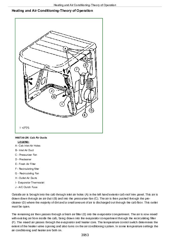
Heating and Air Conditioning-Theory of Operation
Refrigerant System Cycle Operation
Electrical System Operation for Fans and Air Conditioning
High Pressure Switch
Low Pressure Switch
Heater System Operation
John Deere Combines 9780 CTS (S.N. 000001-072799) Diagnostic and Repair Service Manual (TM4635)


