Mercedes-Benz G500, G550 1998-2016 Workshop Repair & Service Manual
Catalog:
Model:
Complete workshop manual contains service, maintenance, and troubleshooting information for the 1998-2016 Mercedes-Benz G-Class 463 G500, G550. Diagnostic and repair procedures are covered in great detail to repair, maintain, rebuild, refurbish or restore your vehicle like a professional mechanic in local service/repair workshop. This cost-effective quality manual is 100% complete and intact as should be without any missing pages. It is the same factory shop manual used by dealers that guaranteed to be fully functional to save your precious time.
This manual for 1998-2016 Mercedes-Benz G-Class 463 G500, G550 is divided into different sections. Each section covers a specific component or system and, in addition to the standard service procedures, includes disassembling, inspecting, and assembling instructions. A table of contents is placed at the beginning of each section. Pages are easily found by category, and each page is expandable for great detail. It is in the cross-platform PDF document format so that it works like a charm on all kinds of devices. You do not need to be skilled with a computer to use the manual.
EXCERPT:
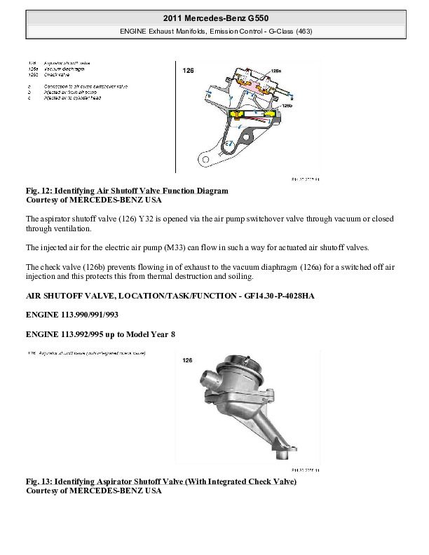
ENGINE Exhaust Manifolds, Emission Control - G-Class (463)
Fig. 5: Identifying Sectional View Of Air Pump Switchover Valve
AIR PUMP SWITCHOVER VALVE, FUNCTION - GF14.30-P-3103-03HA
Fig. 6: Identifying Sectional View Of Air Pump Switchover Valve
The air pump switchover valve (Y32) is actuated directly for a released air injection by the ME-SFI [ME] control unit (N3/10) by means of a ground signal. This causes anchor plate (a) to be pulled by solenoid (d), and rubber seal (f) shuts off air supply (1).
The connection between port 2 and port 3 is opened. Thus there is a vacuum built up from the intake pipe to the aspirator shutoff valves.
In a deenergized condition the connection between connection 1 and connection is reestablished, whereby connection 3 is ventilated.
Fig. 7: Identifying Air Pump Switchover Valve Working Diagram
AIR PUMP SWITCHOVER VALVE, LOCATION/TASK/DESIGN/FUNCTION - GF14.30-P-3103HA
ENGINE 113.990/991/993
ENGINE 113.992/995 up to Model Year 8
...
HVAC Air Compressor, Belt Drives - G-Class
RUNNING DIAGRAM OF POLY V-BELT - AR13.22-P-3902-02B
6-groove single-belt drive, without AC compressor
Fig. 12: Identifying Poly V-Belt Routing (Without AC Compressor)
6-groove single-belt drive, with AC compressor
Fig. 13: Identifying Poly V-Belt Routing (With AC Compressor)
ROUTING DIAGRAM OF POLY-V-BELT - AR13.22-P-3902-02RVK
Shown on engine 113.992
Fig. 14: Poly-V-Belt Routing Diagram
ROUTING DIAGRAM OF POLY V-BELT - AR13.22-P-3902-02VA
Shown on engine 272.963
Fig. 15: Poly V-Belt Routing Diagram
REMOVE/INSTALL POLY-V BELT TENSIONING DEVICE - AR13.25-P-3200B
ENGINE 112.945 in MODEL 463.209/232/233/244/245/250
ENGINE 112 in MODEL 129, 163, 211.061/261/065/265
ENGINE 113.962 in MODEL 463.206/240/241/247/248/249/254
ENGINE 113 (except 113.965/981) in MODEL 129, 163, 202, 208, 210, 211.070/270
ENGINE 112.945 in MODEL 463.243/246
Shown on engine 112
Fig. 16: Identifying Poly-V Belt Tensioning Device Components
...


