Iveco Engines Repair Service Manuals
Catalog:
Model:
Iveco Engines Repair Service Manuals
9806-4900 - Iveco N SERIES EU_2002_88_CE (G-DRIVE application) (N45_N67) Technical and Repair Manual.pdf
603.93.281 - Daily FIA Engine Workshop Manual.pdf
P2D32V001E - Iveco-CNH Vector 8 Industrial applications Technical & Repair Manual.pdf
P2D32N003E - Iveco-CNH NEF Tier 3 Series Industrial applications N45 & N67.X (N45 ENT.X, N45 MSS.X, N45 MNS.X, N45 MST.X, N45 MNT.X, N67 ENT.X, N67 ERT.X, N67 MRT.X, N67 MNT.X) Technical & Repair Manual.pdf
P4D32N003E - Iveco-CNH NEF Tier 3 Series G-Drive applications N45 & N67 (NEF45 SM1X, NEF45 SM2X, NEF67 TE1X, NEF67 TE2X, NEF67 TM1X) Technical & Repair Manual.pdf
P2D32N003GB - Iveco-CNH NEF Tier 3 Series Industrial applications N45 ENT, N67 ENT Workshop Manual Technical & Repair Manual.pdf
P2D32F005E - Iveco-CNH F32 Tier 3 Series Industrial application F32 MNS & F32 MNT Technical & Repair Manual.pdf
P4D32N001E - Iveco-CNH NEF Tier 2 Power Generation application N45 & N60 & N67 (GE_GS NEF 45M-60M-75M-85M-100M-125M-130M-160M-200E Technical & Repair Manual.pdf
P1C32N001GB - Iveco-CNH CNG NEF Series Industrial applications N60 (N60 ENT G) Technical & Repair manual.pdf
L32023007 - Iveco aifo new 8361 series Industrial Engines Workshop Manual.pdf
P2D32C004E - Iveco Cursor Series C9 Engine Technical and Repair Manual.pdf
P1D32C002E - Iveco Cursor Euro 4 Engines C78 C10 C13 Technical and Repair Manual.pdf
CNH NEF with Common Rail General information.pdf
CNH F5 engine with Common Rail General information.pdf
CNH CE Engines Workbook .pdf
CNH Cursor Engine General information.pdf
CNH CE Engines Workbook.pdf
CNH F5 engine with Common Rail General information CE Engines.pdf
CNH NEF with Common Rail General information The electronic “NEF” Engine.pdf
CNH Electronic Service Tool (EST) TIER IV SCR.pdf
Case CX_C Engine Orientation.pdf
CNH F5 engine with Common Rail General information The electronic “F5” Engine.pdf
CNH Cursor Engine General information The “CURSOR” Engine.pdf
CNH NEF with Common Rail The electronic “NEF” Engine.pdf
Mechanical Nef Series Pump Tier 2-3 Teaching Manual.pdf
Common Rail NEF Series Tier 2-3 Engines Teaching Manual.pdf
BONUS:
Iveco - Advanced Diagnostics User Manual.pdf
Iveco - ZF Failure Tree.pdf
MR14StralisSistema Electroelectrónico - español.pdf
MR14StralisSistemaEletroeletrônico - português.pdf
MR_14_StralisHDTrakkerEDCMS6.2_-_Português.pdf
MR 14 Esquemas eléctricos Stralis Eurotronic - Espanhol.pdf
MR_14_StralisHDTrakkerEDCMS6.2_-_Español.pdf
MR_14_StralisHDTrakkerEDC7UC31_-_Español.pdf
MR_14_StralisHDTrakkerEDC7UC31_-_Português.pdf
MR_14_StralisATNEDCMS6.2_-_Português.pdf
MR_14_StralisATNEDC7UC31_-_Português.pdf
MR_14_StralisATNEDCMS6.2_-_Español.pdf
MR_14_StralisATNEDC7UC31_-_Español.pdf
MR 14 Esquemas elétricos Stralis Eurotronic - Português.pdf
MR 14 StralisNR EDC7UC31 - 5801295810 - ESQUEMA ELÉTRICO DE PRINCÍPIO.pdf
Programa de Manutenção Stralis 380 NR.pdf
Programa de Manutenção Stralis NR.pdf
MR 12 Stralis 5 Roda.pdf
MR 12 Stralis 5 Rueda.pdf
MR 10 EuroCargo450E32TDirecaoHidraulica.pdf
MR 10 EuroCargo450E32TDireccionHidraulica.pdf
PUBLICAR MR 08 Stralis NR Suspensiones Mecanicas.pdf
MR 08 Stralis NR Suspensoes Mecanicas.pdf
MR 07 EuroCargo Stralis Eixo Auxiliar (3o. eixo).pdf
MR 07 EuroCargo Tector Stralis Levantador Neumtico Eje Auxiliar - Espanhol.pdf
MR 07 EuroCargo Tector Stralis Suspensor Pneumtico Eixo Auxiliar - Português.pdf
MR 07 Euro Cargo Tector StralisTector Eixo Auxiliar - PORTUGUÊS.pdf
MR 07 Euro Cargo Tector StralisTector Eje Auxiliar - ESPANHOL.pdf
MR 07 Stralis Euro Tech EixoTandemTraseiroRR160.pdf
PUBLICAR MR 07 Euro Cargo Tector Stralis Suspensor Pneumatico Eixo Auxiliar.pdf
PUBLICAR MR 07 EuroCargo Tector Stralis Levantador Neumatico Eje Auxiliar.pdf
MR 07 Tech EixoTraseiro(U180E).pdf
MR 07 Stralis PonteTandemPosteriorRR167.pdf
MR 07 Stralis PuenteTandemPosteriorRR167.pdf
MR 07 EuroCargo Tector Stralis Suspensor Pneumatico Eixo Auxiliar.pdf
MR 07 EuroCargo Tector Stralis Levantador Neumatico Eje Auxiliar.pdf
MR 06 2002-07-31 Eixo Dianteiro - EuroTech.pdf
MR 04 Tech Trakker Stralis Caixas Mudancas ZF16S O.D-T.D.- Português.pdf
MR 04 Tech Trakker Stralis Cajas Cambio ZF16S O.D-T.D.- Espanhol.pdf
MR 03 Stralis Trakker New Trakker Embrague - Espanhol.pdf
MR 03 Stralis Trakker New Trakker Embreagem - Português.pdf
MR 02 Motor Cursor 13 - Páginas 001-065.pdf
MR 02 Motor Cursor 13 - Páginas 066-103.pdf
MR 02 Motor Cursor 13 - Páginas 104-147.pdf
MR 02 Motor Cursor 13 - Páginas 148-157.pdf
MR 01 2002-01-30 Alertas e Códigos Técnicos-Todos veículos.pdf
MR 1 2002-01-30 Geral - Alertas e Códigos Técnicos - Português.pdf
MR 1 2006-05-30 Geral - Alertas y Códigos Técnicos - Espanhol.pdf
603.93.281 - Daily FIA Engine Workshop Manual...3
9806-4900 - Iveco N SERIES EU_2002_88_CE (G-DRIVE application) (N45_N67) Technical and Repair Manual...269
CNH CE Engines Workbook ...595
CNH CE Engines Workbook...638
CNH Cursor Engine General information The “CURSOR” Engine...681
CNH Cursor Engine General information...835
CNH Electronic Service Tool (EST) TIER IV SCR...989
03-03 EST TIER IV SCR.pdf...989
03-04 EST T4 F5H DPF...1033
CNH F5 engine with Common Rail General information CE Engines...1067
CNH F5 engine with Common Rail General information The electronic “F5” Engine...1261
CNH F5 engine with Common Rail General information...1454
CNH NEF with Common Rail General information The electronic “NEF” Engine...1648
CNH NEF with Common Rail General information...1757
CNH NEF with Common Rail The electronic “NEF” Engine...1974
Case CX_C Engine Orientation...2083
(008A) Isuzu CXC Engine...2083
(008B) CXC DPD Feature and Operation (1)...2173
(008C) CXC Service Monitor...2208
Common Rail NEF Series Tier 2-3 Engines Teaching Manual...2234
L32023007 - Iveco aifo new 8361 series Industrial Engines Workshop Manual...2399
Mechanical Nef Series Pump Tier 2-3 Teaching Manual...2463
P1C32N001GB - Iveco-CNH CNG NEF Series Industrial applications N60 (N60 ENT G) Technical & Repair manual...2613
CNG NEF SERIES - N60 ENT G...2613
CNG NEF ENGINES...2615
SPECIAL REMARKS...2617
PRELIMINARY REMARKS...2618
SYMBOLS - WARNINGS...2618
Graph and symbols...2619
Part 1 - F4B ENGINES...2621
UPDATING...2623
SECTION 1 - General specifications...2625
CORRESPONDENCE BETWEEN IVECO CODE AND IVECO MOTORS COMMERCIAL CODE...2627
LUBRICATION...2629
OIL VAPOUR RECIRCULATING SYSTEM...2630
COOLING SYSTEM...2631
AIR INDUCTION BOOST DIAGRAM...2632
Description...2632
SECTION 2 - Fuel...2633
CHEMICAL COMPOSITION OF NATURAL GAS (CNG)...2635
ADVANTAGES OF METHANE GAS UTILIZATION IN AUTOMOTIVE...2635
Motor advantages of methane gas utilization...2636
Disadvantages of methane utilization in engines...2636
Torque and power typical curves - F4BE0641A engines...2637
GAS EMISSIONS...2638
Main pollutants...2638
Emissions of Iveco CNG engine compared to ETC cycle emissions - gas of reference: G20 and G25...2639
IGNITION AND INJECTION INTEGRATED SYSTEM...2640
Characteristics...2640
General items...2640
ELECTRIC INJECTORS...2641
AIR SUCTION CIRCUIT...2642
Debimeter (Air flow sensor)...2642
Throttle valve body...2642
PRESSURE REDUCER...2643
STEEL HOSE...2646
OXYGEN SENSOR...2647
SECTION 3 - Use...2649
GENERAL SPECIFICATIONS...2651
GENERAL PROPERTIES...2652
PART ONE - MECHANICAL COMPONENTS...2653
ENGINE OVERHAUL...2655
Preface...2655
Engine disassembly on the stand...2655
Cylinder head removal...2658
Installation of components...2663
Timing...2663
Mounting the flywheel housing...2664
Engine flywheel...2665
Mounting the cylinder head...2670
Completion of the engine...2674
Checks and inspections...2677
PART TWO - ELECTRICAL EQUIPMENT...2679
GENERAL ITEMS...2681
MF3 — IGNITION AND INJECTION INTEGRATED SYSTEM...2682
MF3 system characteristics...2682
Injection management...2682
Fuel cutoff in release step...2683
Combustion control by Lambda Probe...2683
System self-adaptation...2683
Startup management...2684
Engine rotation speed management...2684
Ignition management...2685
Additional loads management...2685
Turboblower regulation...2685
Connection to vehicle through CAN line (to gearbox and dashboard central units)...2686
Acceleration deactivation (option)...2686
VEHICLE FUNCTIONS APPLIED BY CONTROL UNIT MF3...2687
MF3 CONTROL UNIT INSTALLATION...2688
MF3 CONTROL UNIT WIRING DIAGRAM (FIRST PART)...2689
MF3 CONTROL UNIT WIRING DIAGRAM (SECOND PART)...2690
KEY...2691
PIN OUT MF3...2692
COMPONENTS...2695
Electric injectors...2695
Air suction circuit...2696
Debimeter (Air flow sensor)...2696
Throttle valve body...2697
Idling actuator...2698
Fuel cut-off...2699
Electronic injection (Characteristics)...2699
Lambda sensor...2700
Connections...2700
Air temperature-pressure sensor...2701
Engine oil temperature-pressure sensor...2701
Crankshaft sensor...2702
Timing sensor...2702
Wastegate solenoid valve...2703
TARTARINI META pressure reducer...2704
Steel hose...2707
Throttle valve setting at idling...2708
PART THREE - TROUBLESHOOTING...2709
PREFACE...2711
BLINK-CODE - GENERAL INFORMATION...2712
Anomaly warning led...2712
Detectable failures...2712
Self-diagnosis...2713
Recovery (operation with components subjected to failure)...2713
VDO EGAS2 Diagnosis System...2714
Error deleting...2714
TROUBLESHOOTING BY MEANS OF BLINK-CODES...2715
MF3 Diagnosis...2715
VDO DIAGNOSIS...2720
Blink-code reading...2720
Clearing the error memory...2720
VDO EGAS2 system diagnosis...2721
TROUBLESHOOTING BY SYMPTOMS...2722
PART FOUR - MAINTENANCE PLANNING...2729
MAINTENANCE PLANNING...2731
Recovery...2731
Planning of controls and periodical intervention...2731
Checks not included in maintenance planning-daily checks...2732
MAINTENANCE PROCEDURES...2732
Checks and controls...2732
Engine oil level check...2732
Check of fuel system...2733
Cooling system check...2733
Lubricating system check...2733
Checking/replacing the blow-by filter...2733
Check of drive belt tensioning...2734
Check of belt’s tear and wear status...2734
Check and setting of tappet clearance...2734
Changing the engine oil and oil filter...2735
Filter replacement procedure...2735
Alternator belt - water pump replacement...2736
SECTION 4 - General overhaul...2737
GENERAL SPECIFICATIONS...2739
CLEARANCE DATA...2740
ENGINE OVERHAUL...2746
ENGINE REMOVAL AT THE BENCH...2746
REPAIR INTERVENTIONS...2747
CYLINDER GROUP...2747
Controls and measurements...2747
Head face check on the cylinder group...2749
TIMING SYSTEM...2749
Camshaft...2749
Cam lift check and pin alignment check...2750
BUSHES...2750
Bush replacement...2751
Tappets...2751
Fitting tappets - camshaft...2751
OUTPUT SHAFT...2752
Measuring journals and crankpins...2752
Replacing oil pump control gear...2755
Fitting main bearings...2755
Finding journal clearance...2755
Checking output shaft shoulder clearance...2756
CONNECTING ROD - PISTON ASSEMBLY...2757
Pistons...2758
Measuring piston diameter...2758
Piston pins...2758
Conditions for proper pin-piston coupling...2758
Split rings...2758
Connecting rods...2759
Bushes...2760
Checking connecting rods...2760
Checking torsion...2761
Checking bending...2761
Fitting connecting rod-piston assembly...2761
Connecting rod-piston coupling...2761
Fitting split rings...2762
Fitting connecting rod-piston assembly into cylinder barrels...2763
Finding crankpin clearance...2763
Checking piston protrusion...2764
CYLINDER HEAD...2765
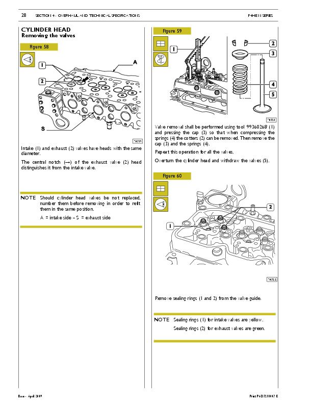
Removing the valves...2765
Checking the cylinder head supporting surface...2765
Checking the cylinder head water seal...2766
VALVES...2766
Valve descaling, check and grinding...2766
Checking the play between the valve stem, valve guide and valve centring...2767
VALVE GUIDE...2767
VALVE SEATS...2767
Valve seat reconditioning - replacement...2767
VALVE SPRINGS...2769
TIGHTENING TORQUES...2770
SECTION 5 - Tools...2773
TOOLS...2775
Appendix...2781
SAFETY PRESCRIPTIONS...2783
Standard safety prescriptions...2783
Prevention of injury...2783
During maintenance...2783
Respect of the Environment...2784
P1D32C002E - Iveco Cursor Euro 4 Engines C78 C10 C13 Technical and Repair Manual...2785
CURSOR SERIES EURO 4...2785
CURSOR EURO 4 ENGINES...2787
SPECIAL REMARKS...2789
Graph and symbols...2790
Part 1 - F2B CURSOR EURO 4 ENGINES...2791
UPDATING...2793
SECTION 1 - General specifications...2795
CORRESPONDENCE BETWEEN TECHNICAL CODE AND COMMERCIAL CODE...2797
ENGINE SECTIONS...2799
LUBRICATION...2801
Oil pump...2802
Overpressure valve...2802
Oil pressure control valve...2803
Heat exchanger...2803
By-pass valve inside the filter support/heat exchanger assembly...2804
Thermostatic valve...2804
Engine oil filters...2804
Valve integrated in piston cooling nozzle...2805
COOLING...2806
Description...2806
Operation...2806
Water pump...2807
Thermostat...2807
TURBOCHARGING...2808
VGT TURBOCHARGER...2808
Actuator...2809
Solenoid valve for VGT control...2809
DeNOx SYSTEM 2...2810
General remarks...2810
Tank...2812
AdBlue fluid level gauge control...2812
By-pass valve...2812
Pump module...2813
Dosing module...2813
Catalyst...2813
Exhaust gas temperature sensor...2814
Humidity detecting sensor...2815
SECTION 2 - Fuel...2817
FUEL FEED...2819
Overpressure valve...2820
Feed pump...2820
Injector-pump...2821
Injector Phases...2822
Pressure damper...2823
SECTION 3 - Vehicle application...2825
GENERAL FEATURES...2827
PART ONE - MECHANICAL COMPONENTS...2829
DISMANTLING THE ENGINE ON THE BENCH...2831
ASSEMBLING THE ENGINE ON THE BENCH...2838
Diagram showing the underblock fixing screws tightening order...2840
Fitting the connecting rod-piston assembly into the cylinder liners...2841
Mounting cylinder head...2842
Fitting engine flywheel...2844
Fitting camshaft...2845
Fitting pump-injectors...2846
Fitting rocker-arm shaft assembly...2846
Camshaft timing...2847
Phonic wheel timing...2849
Intake and exhaust rocker play adjustment and pre-loading of rockers controlling pump injectors...2850
ENGINE COMPLETION...2851
PART TWO - ELECTRICAL EQUIPMENT...2853
Components on the engine F2B...2855
BLOCK DIAGRAM...2856
EDC SYSTEM FUNCTIONS...2857
EDC 7 UC31 electronic control unit...2860
Electric injector connector ”A”...2861
Sensor connector ”C”...2862
Chassis connector ”B”...2863
Pump injector (78247)...2865
Exhaust brake solenoid valve (78050)...2867
Solenoid valve for VGT control...2867
Distribution pulse transmitter (48042)...2868
Engine coolant temperature sensor (85153)...2869
Fuel temperature sensor (47042)...2870
Flywheel pulse transmitter (48035)...2871
Turbine rpm sensor (48043)...2872
Air pressure/temperature sensor (85156)...2873
Oil temperature/pressure sensor (42030 / 47032)...2873
Pre-post reheat resistor (61121)...2874
PART THREE - TROUBLESHOOTING...2875
PREFACE...2877
DTC error codes with EDC7 UC31 central unit...2879
GUIDELINE FOR TROUBLESHOOTING...2901
PART FOUR - MAINTENANCE PLANNING...2905
MAINTENANCE...2907
Maintenance services scheme...2907
MAINTENANCE INTERVALS...2908
On road application...2908
Off road application (quarries-construction sites)...2908
Off road application (on road usage)...2908
CHECKS AND/OR MAINTENANCEWORK...2909
On road application...2909
Off road application...2909
NON-PROGRAMMED/TIMED OPERATIONS...2910
On road application...2910
Off road application (quarries-construction sites)...2910
Off road application (on road usage)...2910
SECTION 4 - General overhaul...2911
GENERAL CHARACTERISTICS...2913
ASSEMBLY CLEARANCE DATA...2915
REPAIR OPERATIONS...2923
CYLINDER BLOCK...2923
Checks and measurements...2923
CYLINDER LINERS...2924
Removal of cylinder liners...2925
Fitting and checking protrusion...2925
CRANKSHAFT...2926
Measuring main journals and crank pins...2927
Preliminary measurement of main and big end bearing shell selection data...2928
Selecting the main and big end bearing shells...2929
Defining the class of diameter of themain journals and crankpins (Journals with nominal diameter)...2930
Selection of main half-bearings (nominal diameter pins)...2931
Selection of main half-bearings (rectified pins)...2932
Selecting the big end bearing shells (journals with nominal diameter)...2933
Selection of connecting rod half-bearings (rectified pins)...2934
Replacing the timing control gear and the oil pump...2935
Checking main journal installation clearance...2935
Checking crankshaft end float...2936
PISTON-CONNECTING ROD ASSEMBLY...2937
Removal...2937
Measuring the diameter of the pistons...2938
Conditions for correct gudgeon pin-piston coupling...2938
Piston rings...2939
CONNECTING ROD...2940
Checking connecting rod alignment...2941
Mounting the connecting rod - piston assembly...2941
Mounting the piston rings...2941
Fitting the connecting rod-piston assembly into the piston liners...2942
Piston protrusion check...2942
Checking assembly clearance of big end pins...2943
CYLINDER HEAD...2943
Dismounting the valves...2943
Checking the planarity of the head on the cylinder block...2943
VALVE...2944
Removing deposits and checking the valves...2944
VALVE GUIDES...2944
Replacing of valve guides...2945
Replacing - Reaming the valve seats...2945
REPLACING INJECTOR HOLDER CASES...2945
Removal...2945
Checking protrusion of injectors...2947
TIMING GEAR...2948
Camshaft drive...2948
Intermediate gear pin...2948
Idler gear...2948
Twin idler gear...2948
Replacing the bushings...2948
Check of cam lift and timing system shaft pins alignment...2949
Bushes...2950
Replacing camshaft bushes using beater 99360487...2951
Removing bushes...2951
Assembling bushes...2951
VALVE SPRINGS...2952
Fitting the valves and oil seal ring...2952
ROCKER SHAFT...2953
Shaft...2953
Rocker...2953
REPAIRING ACTIONS...2954
Variable geometry movement control...2954
Checking the actuator...2954
Checking actuator travel...2955
Cleaning turbine body...2955
TIGHTENING TORQUES...2958
Underblock fixing screws tightening sequence...2961
Diagram of cylinder head fixing screws tightening sequence...2962
Diagram of rocker shaft fixing screws tightening sequence...2962
Diagram of exhaust manifold fixing screws tightening sequence...2962
Diagram of turbocharger fixing screws and nuts tightening sequence...2963
Diagram of heat exchanger fixing screws tightening sequence...2963
Diagram of engine oil sump fixing screws tightening sequence...2963
Diagram of rocker arm cap fixing screws tightening sequence...2964
SECTION 5 - Tools...2965
TOOLS...2967
Appendix...2977
SAFETY PRESCRIPTIONS...2979
Part 2 - F3A CURSOR EURO 4 ENGINES...2981
UPDATING...2983
SECTION 1 - General specifications...2985
CORRESPONDENCE BETWEEN TECHNICAL CODE AND COMMERCIAL CODE...2987
VIEWS OF THE ENGINE...2989
LUBRICATION...2993
Oil pump...2994
Overpressure valve...2994
Oil pressure control valve...2995
Heat exchanger...2995
By-pass valve...2996
Thermostatic valve...2996
Engine oil filters...2996
Valve integrated in piston cooling nozzle...2997
COOLING...2998
Description...2998
Operation...2998
Water pump...2999
Thermostat...2999
TURBOCHARGING...3000
Turbocharger HOLSET HE531V...3000
Actuator...3001
Solenoid valve for VGT control...3001
DeNOx SYSTEM 2...3002
General remarks...3002
Tank...3004
AdBlue fluid level gauge control...3004
By-pass valve...3004
Pump module...3005
Dosing module...3005
Catalyst...3005
Exhaust gas temperature sensor...3006
Humidity detecting sensor...3007
SECTION 2 - Fuel...3009
FEEDING...3011
Overpressure valve...3012
Feed pump...3012
Injector-pump...3012
Replacing injectors-pump...3013
Pressure damper...3013
SECTION 3 - Vehicle application...3015
GENERAL FEATURES...3017
PART ONE - MECHANICAL COMPONENTS...3019
DISMANTLING THE ENGINE ON THE BENCH...3021
ENGINE ASSEMBLY ON BENCH...3028
Diagram of tightening sequence of crankcase base fixing screws...3030
Fitting connecting rod - piston assemblies in cylinder liners...3031
Mounting cylinder head...3032
Fitting engine flywheel...3034
Fitting camshaft...3035
Fitting pump-injectors...3036
Fitting rocker-arm shaft assembly...3036
Camshaft timing...3037
Phonic wheel timing...3039
Intake and exhaust rocker play adjustment and pre-loading of rockers controlling pump injectors...3040
Completing Engine Assembly...3041
PART TWO - ELECTRICAL EQUIPMENT...3045
Components on the engine F3A...3047
BLOCK DIAGRAM...3048
EDC SYSTEM FUNCTIONS...3049
EDC 7 UC31 electronic control unit...3052
Electric injector connector ”A”...3053
Sensor connector ”C”...3054
Chassis connector ”B”...3055
Pump injector (78247)...3057
Exhaust brake solenoid valve (78050)...3059
Solenoid valve for VGT control...3059
Distribution pulse transmitter (48042)...3060
Engine coolant temperature sensor (85153)...3061
Fuel temperature sensor (47042)...3062
Flywheel pulse transmitter (48035)...3063
Turbine rpm sensor (48043)...3064
Air pressure/temperature sensor (85156)...3065
Oil temperature/pressure sensor (42030 / 47032)...3065
Pre-post reheat resistor (61121)...3066
PART THREE - TROUBLESHOOTING...3067
PREFACE...3069
DTC error codes with EDC7 UC31 central unit...3071
GUIDELINE FOR TROUBLESHOOTING...3093
PART FOUR - MAINTENANCE PLANNING...3097
MAINTENANCE...3099
Maintenance services scheme...3099
Maintenance intervals...3100
CHECKS AND/OR MAINTENANCEWORK...3100
NON-PROGRAMMED/TIMED OPERATIONS...3101
SECTION 4 - General overhaul...3103
GENERAL CHARACTERISTICS...3105
ASSEMBLY CLEARANCE DATA...3107
REPAIR OPERATIONS...3115
CYLINDER BLOCK...3115
Checks and measurements...3115
CYLINDER LINERS...3116
Removing cylinder liners...3117
Fitting and checking protrusion...3117
CRANKSHAFT...3118
Measuring the main journals and crankpins...3119
Preliminary measurement of main and big end bearing shell selection data...3120
Selecting the main and big end bearing shells...3121
Defining the class of diameter of themain journals and crankpins (Journals with nominal diameter)...3122
Selecting the main bearing shells (Journals with nominal diameter)...3123
Selecting the main bearing shells (ground journals)...3124
Replacing the timing gear and oil pump...3127
Checking main journal assembly clearance...3127
Checking crankshaft end float...3128
PISTON CONNECTING ROD ASSEMBLY...3129
Removal...3129
Measuring the diameter of the pistons...3130
Conditions for correct gudgeon pin-piston coupling...3130
Piston rings...3131
CONNECTING RODS...3132
Bushings...3133
Checking connecting rods...3133
Mounting the connecting rod — piston assembly...3134
Mounting the piston rings...3134
Fitting the big end bearing shells...3134
Fitting connecting rod - piston assemblies in the cylinder liners...3135
Checking piston protrusion...3135
Checking crankpin assembly clearance...3136
CYLINDER HEAD...3136
Disassembly the valves...3136
Checking head bearing surface on cylinder block...3136
Valves...3137
Removing deposits and checking the valves...3137
Valve seats...3137
Checking clearance between valve-stem and associated valve guide...3138
Valve guides...3138
Replacing injector cases...3138
Checking injector protrusion...3140
TIMING GEAR...3141
Camshaft drive...3141
Idler gear and pin...3141
Twin intermediate gear and pin...3141
Replacing the bushings...3141
Check of cam lift and timing system shaft pins alignment...3142
Camshaft...3143
Bushings...3143
Replacing camshaft bushings with drift 99360499...3144
Dismounting the bushings...3144
Mounting the bushings...3144
Valve springs...3145
ROCKER SHAFT...3146
Shaft...3147
Rocker arms...3147
REPAIR...3148
Variable geometry movement control...3148
Checking the actuator...3149
Checking actuator travel...3149
Cleaning turbine body...3150
TIGHTENING TORQUES...3153
Diagrams of tightening sequence for screws fixing crankcase base...3156
Diagram of cylinder head fixing screws tightening sequence...3157
Diagram of exhaust manifold fixing screws tightening sequence...3157
Diagram of turbocharger fixing screws and nuts tightening sequence...3157
Diagram of tightening sequence for heat exchanger screws...3158
Diagram of tightening sequence for engine oil sump screws...3158
Diagram of tightening sequence for screws fixing rocker cover...3158
F3A ENGINE...3159
Diagram of cylinder head fixing screws tightening sequence...3159
SECTION 5 - Tools...3161
TOOLS...3163
Appendix...3173
SAFETY PRESCRIPTIONS...3175
Part 3 - F3B CURSOR EURO 4 ENGINES...3177
UPDATING...3179
SECTION 1 - General specifications...3181
CORRESPONDENCE BETWEEN TECHNICAL CODE AND COMMERCIAL CODE...3183
VIEWS OF ENGINE...3185
LUBRICATION...3188
Oil pump...3189
Overpressure valve...3189
Oil pressure control valve...3190
Heat exchanger...3190
By-pass valve...3191
Thermostatic valve...3191
Engine oil filters...3191
Valve integrated in piston cooling nozzle...3192
COOLING...3193
Description...3193
Operation...3193
Water pump...3194
Thermostat...3194
TURBOCHARGING...3195
Turbocharger HOLSET HE 551 V...3195
Actuator...3196
Solenoid valve for VGT control...3196
DeNOx SYSTEM 2...3197
General remarks...3197
Tank...3199
AdBlue fluid level gauge control...3199
By-pass valve...3199
Pump module...3200
Dosing module...3200
Catalyst...3200
Exhaust gas temperature sensor...3201
Humidity detecting sensor...3202
SECTION 2 - Fuel...3203
FEEDING...3205
Overpressure valve...3206
Feed pump...3206
Injector-pump...3206
Pressure damper...3206
SECTION 3 - Vehicle application...3207
CLEARANCE DATA...3209
PART ONE - MECHANICAL COMPONENTS...3211
DISASSEMBLY THE ENGINE ON THE BENCH...3213
ASSEMBLING THE ENGINE ON THE BENCH...3221
Diagram of tightening sequence of crankcase base fixing screws...3223
Fitting connecting rod - piston assemblies in cylinder liners...3224
Mounting cylinder head...3225
Fitting flywheel box...3226
ENGINE FLYWHEEL...3227
Fitting engine flywheel...3227
Fitting camshaft...3228
Fitting pump-injectors...3229
Fitting rocker-arm shaft assembly...3229
Camshaft timing...3230
Phonic wheel timing...3232
Intake and exhaust rocker play adjustment and pre-loading of rockers controlling pump injectors...3233
Completing Engine Assembly...3234
PART TWO - ELECTRICAL EQUIPMENT...3237
Components on the engine F3B...3239
BLOCK DIAGRAM...3240
EDC SYSTEM FUNCTIONS...3241
EDC 7 UC31 electronic control unit...3244
Electric injector connector ”A”...3245
Sensor connector ”C”...3246
Chassis connector ”B”...3247
Pump injector (78247)...3249
Exhaust brake solenoid valve (78050)...3251
Solenoid valve for VGT control...3251
Distribution pulse transmitter (48042)...3252
Engine coolant temperature sensor (85153)...3253
Fuel temperature sensor (47042)...3254
Flywheel pulse transmitter (48035)...3255
Turbine rpm sensor (48043)...3256
Air pressure/temperature sensor (85156)...3257
Oil temperature/pressure sensor (42030 / 47032)...3257
Pre-post reheat resistor (61121)...3258
PART THREE - TROUBLESHOOTING...3259
PREFACE...3261
DTC error codes with EDC7 UC31 central unit...3263
GUIDELINE FOR TROUBLESHOOTING...3285
PART FOUR - MAINTENANCE PLANNING...3289
MAINTENANCE...3291
Maintenance services scheme...3291
MAINTENANCE INTERVALS...3292
On road application...3292
Off road application (quarries-construction sites)...3292
Off road application (on road usage)...3292
CHECKS AND/OR MAINTENANCEWORK...3293
On road application...3293
Off road application...3293
NON-PROGRAMMED/TIMED OPERATIONS...3294
On road application...3294
Off road application (quarries-construction sites)...3294
Off road application (on road usage)...3294
SECTION 4 - General overhaul...3295
GENERAL CHARACTERISTICS...3297
ASSEMBLY DATA - CLEARANCE...3299
REPAIRS...3307
CYLINDER BLOCK...3307
Checks and measurements...3307
Cylinder liners...3308
Removing cylinder liners...3309
Assembly and checking protrusion...3309
Crankshaft...3310
Measuring the main journals and crankpins...3311
Preliminary measurement of main and big end bearing shell selection data...3312
Selecting the main bearing and big end bearing shells...3313
Defining the class of diameter of themain journals and crankpins (Journals with nominal diameter)...3314
Selecting the main bearing shells (Journals with nominal diameter)...3315
Selecting the main bearing shells (ground journals)...3316
Selecting the big end bearing shells (journals with nominal diameter)...3317
Replacing the timing gear and oil pump...3319
Checking main journal assembly clearance...3319
Checking crankshaft end float...3320
PISTON CONNECTING ROD ASSEMBLY...3321
Removal...3321
Measuring the diameter of the pistons...3322
Conditions for correct gudgeon pin-piston coupling...3322
Piston rings...3323
Connecting rod...3324
Connecting rods bushings...3325
Checking connecting rods...3325
Mounting the connecting rod — piston assembly...3326
Mounting the piston rings...3326
Fitting the big end bearing shells...3326
Fitting connecting rod - piston assemblies in the cylinder liners...3327
Checking piston protrusion...3327
Checking crankpin assembly clearance...3328
CYLINDER HEAD...3328
Dismounting the valves...3328
Checking head bearing surface on cylinder block...3328
Valves...3329
Valve seats...3329
Checking clearance between valve-stem and associated valve guide...3330
Valve guides...3330
Replacing injector cases...3330
Assembly...3331
Checking injector protrusion...3332
TIMING GEAR...3333
Camshaft drive...3333
Idler gear pin...3333
Idler gear...3333
Twin intermediate gear pin...3333
Twin idler gear...3333
Replacing the bushings...3333
Timing system...3334
Checking cam lift and pin alignment...3334
Bushings...3335
Valve springs...3337
ROCKER SHAFT...3338
Shaft...3339
Rocker arms...3339
REPAIR...3340
Variable geometry movement control...3340
Checking the actuator...3341
Checking actuator travel...3341
Cleaning turbine body...3342
TIGHTENING TORQUE...3345
Diagram of tightening sequence of crankcase base fixing screws...3348
Diagram of tightening sequence of exhaust manifold fixing screws...3349
Diagram of tightening sequence of exhaust manifold fixing screws...3349
Diagram of tightening sequence of screws and nuts fixing turbocharger on exhaust manifold...3349
SECTION 5 - Tools...3353
TOOLS...3355
Appendix...3365
SAFETY PRESCRIPTIONS...3367
P2D32C004E - Iveco Cursor Series C9 Engine Technical and Repair Manual...3369
P2D32F005E - Iveco-CNH F32 Tier 3 Series Industrial application F32 MNS & F32 MNT Technical & Repair Manual...3531
F32 TIER 3 SERIES - Industrial application...3531
Technical and Repair manual...3531
F32 SERIES...3533
Introduction...3535
PREFACE...3537
SYMBOLS -Warnings...3537
Service operations...3537
GENERAL WARNINGS...3539
GENERAL WARNINGS ON THE ELECTRIC SYSTEM...3541
Bonding and screening...3542
CONVERSIONS BETWEEN THE MAIN UNITS OF MEASUREMENT OF THE INTERNATIONAL SYSTEM AND MOST USED DERIVED QUANTITIES...3543
KEY OF LECTURE OF THE HEADINGS AND FOOTNOTES...3544
Part 1 - F32 SERIES...3545
UPDATING...3547
SECTION 1 - General specifications...3549
General specifications...3549
CORRESPONDENCY BETWEEN TECHNICAL CODING AND COMMERCIAL CODING...3551
ENGINE VIEWS (for F5CE9454E*A005, F5CE9484D*A002 engines)...3552
ENGINE VIEWS (for F5CE5454B*A004 engines)...3553
ENGINE LUBRICATION SYSTEM...3554
Oil pump...3555
Engine oil filter...3556
ENGINE OIL VAPOUR RECIRCULATION...3557
ENGINE COOLING SYSTEM...3558
For engines without external EGR...3558
For engines with external EGR...3559
WATER PUMP...3560
THERMOSTAT...3560
Working system...3560
HEAT EXCHANGER...3561
EGR EXHAUST GAS RECYCLE SYSTEM...3562
Internal EGR operating on the intake valves (for F5CE9454, F5CE9484 engines)...3562
Intake cam profile...3562
External E.G.R. system(for F5CE5454 engines)...3563
Working system...3563
BOOSTING...3564
For engines without external EGR...3564
For engines with external EGR...3565
SECTION 2 - Supply...3567
Supply...3567
SUPPLY...3569
PIPE LAYOUT...3570
Working system description...3571
SUPPLY PUMP...3572
Identification coding example...3572
WORKING SYSTEM DESCRIPTION...3573
Supply phase...3573
Delivery phase...3573
End of delivery phase...3574
Engine stop...3574
L.D.A. Load Delivery Adjustment device...3575
Working system...3575
PRIMING PUMP...3576
FUEL FILTER...3577
SECTION 3 - Industrial application...3579
Industrial application...3579
MAIN SPECIFICATIONS...3581
PART ONE - MECHANICAL COMPONENTS...3583
ENGINE DISASSEMBLY ON BENCH...3585
Cylinder 1 T.D.C. search...3586
BOSCH VE 4/12F Pump...3587
Timing gearcase...3590
Rear side component assembly...3592
Timing...3594
Piston projection measurement...3595
Checks and inspections...3603
Rocker cover blow-by removal and refitting...3604
Rotary feed pump disassembly and assembly procedure...3608
Injection pump static advance control on engine at cylinder 1 TDC...3611
Power takeoff...3611
PART TWO - ELECTRICAL EQUIPMENT...3613
ENGINE CABLE FOR EXTERNAL EGR SYSTEM (for F5CE5454 engines)...3615
EXTERNAL EGR E.C.U. ELECTRICAL LAYOUT (for F5CE5454 engines)...3616
External EGR E.C.U. (for F5CE5454 engines)...3617
Pin out EGR E.C.U...3618
KSB - BOSCH PUMP CONNECTION CABLE...3619
Engine cooling liquid temperature sensor (for F5CE5454 engines)...3620
Oil pressure switch...3621
Cooling liquid temperature sensor for KSB...3622
Air pressure temperature sensor (for F5CE5454 engines)...3623
Engine drive shaft sensor (for F5CE5454 engines)...3624
EGR Solenoid valve (for F5CE5454 engines)...3625
Delivery specifications...3625
Starter...3626
BOSCH 14V Alternator...3627
PART THREE - TROUBLESHOOTING...3629
DIAGNOSIS BY FAILURE...3631
PART FOUR - MAINTENANCE PLANNING...3637
SCHEDULED MAINTENANCE...3639
Servicing Plan...3639
Overhaul and/or basic maintenance...3639
Checks not included in maintenance planning-daily checks...3640
MAINTENANCE PROCEDURES...3640
Checks and controls...3640
SECTION 4 - Mechanical overhaul...3647
GENERAL SPECIFICATIONS...3649
DATA - ASSEMBLY SLACKS...3650
ENGINE OVERHAUL...3656
ENGINE DISASSEMBLY ON BENCH...3656
REPAIRS...3657
CYLINDER UNIT...3657
Checks and measurements...3657
Checking head base surface on cylinder unit...3658
TIMING SYSTEM...3659
Camshaft...3659
Checking cam lift and pin alignment...3659
BUSH...3659
Bush replacement...3661
Tappets...3661
Tappet - camshaft assembly...3661
ENGINE DRIVE SHAFT...3662
Measurement of main journals and crankshaft bearing pins...3662
Crankshaft bearing assembly...3664
Crankshaft assembly...3664
Checking output shaft shoulder clearance...3665
CONNECTING ROD - PISTON ASSEMBLY...3665
Piston pins...3667
Conditions for the correct coupling of pins and pistons...3667
Split rings...3667
Connecting rods...3668
Connecting rod-piston unit assembly...3669
Connecting rod-piston coupling...3669
Snap ring assembly...3669
Fitting connecting rod-piston assembly into cylinder barrels...3670
Connecting rod caps fitting...3670
Piston projection check...3671
CYLINDER HEAD...3672
Valve disassembly...3672
Cylinder head base surface check...3673
VALVES...3673
Valve scaling, checking and grinding...3673
VALVE GUIDE...3674
Valve guide replacement...3674
VALVE SEATS...3674
CYLINDER HEAD ASSEMBLY...3675
Cylinder head reassembly...3675
TORQUE SETTING...3676
SECTION 5 - Tools...3681
Tools...3681
TOOLS...3683
Appendix...3689
Appendix...3689
SAFETY PRESCRIPTIONS...3691
Standard safety prescriptions...3691
Prevention of injury...3691
During maintenance...3691
Respect of the Environment...3692
P2D32N003E - Iveco-CNH NEF Tier 3 Series Industrial applications N45 & N67.X (N45 ENT.X, N45 MSS.X, N45 MNS.X, N45 MST.X, N45 MNT.X, N67 ENT.X, N67 ERT.X, N67 MRT.X, N67 MNT.X) Technical & Repair Manual...3693
NEF TIER 3 SERIES...3693
Technical and Repair manual...3693
PRELIMINARY REMARKS...3695
SYMBOLS - WARNINGS...3695
GENERAL WARNINGS...3696
GENERAL WARNINGS ON THE ELECTRIC SYSTEM...3698
Bonding and screening...3699
OPTIONAL ELECTRICAL AND MECHANICAL PARTS INSTALLATIONS...3700
CONVERSIONS BETWEEN THE MAIN UNITS OF MEASUREMENT OF THE INTERNATIONAL SYSTEM AND MOST USED DERIVED QUANTITIES...3700
NEF TIER 3 ENGINES...3701
Part 1 - F4HE NEF ENGINES...3703
SPECIAL REMARKS...3705
SYMBOLS - ASSISTANCE OPERATIONS...3706
UPDATING...3707
SECTION 1 - General specifications...3709
CORRESPONDENCE BETWEEN TECHNICAL CODE AND COMMERCIAL CODE...3711
LUBRICATION...3712
4-cylinder engine version...3712
6-cylinder engine version...3713
OIL VAPOUR RECYCLING...3714
Version with blow-by filter...3714
Version without blow-by filter...3715
COOLING SYSTEM...3716
4-cylinder engine version...3716
6-cylinder engine version...3717
AIR INDUCTION - BOOST DIAGRAM...3718
Description...3718
EXHAUSTGAS RE-CIRCULATION SYSTEM (EGR)...3719
SECTION 2 - Fuel...3721
HIGH PRESSURE ELECTRONIC INJECTION SYSTEM (COMMON RAIL)...3723
EDC 7 OPERATION...3724
WORKING PROCESS...3725
FUEL SYSTEM LAYOUT...3726
MECHANICAL FEEDING PUMP...3727
CP3 HIGH PRESSURE PUMP...3728
RAIL...3732
ELECTRO-INJECTOR...3733
PRESSURE LIMITER FOR FUEL RETURN...3734
SECTION 3 - Duty-industrial application...3735
GENERAL SPECIFICATIONS...3737
Section pictures of complete engine - common rail version...3737
Clearance data - 4 cyl...3738
Clearance data - 6 cyl...3739
PART ONE - MECHANICAL COMPONENTS...3741
ENGINE OVERHAUL...3743
Preface...3743
Engine setting operations for the assembly on turning stand...3743
Disassembly of application components...3744
Assembly of application components...3751
Completion of the engine...3763
Checks and inspections...3764
PART TWO - ELECTRICAL EQUIPMENT...3765
LOCATION OF THE MAIN ELECTRICAL COMPONENTS...3767
EDC7 ECU...3768
Cable on engine...3769
Injectors connector (A)...3770
Sensors connector (C)...3770
Crankshaft sensor...3771
Timing sensor...3771
Supercharging air pressure - temperature sensor...3772
Engine oil temperature-pressure sensor...3772
Fuel temperature and pressure sensor...3773
Electro-injectors...3774
Pre-post heating resistance and contactor...3775
Coolant temperature sensor...3776
Fuel temperature sensor...3777
High pressure pump - pressure regulator...3778
PART THREE - TROUBLESHOOTING...3779
METHODS OF DIAGNOSIS...3781
PT-01...3781
PREFACE...3782
PT-01 PORTABLE TESTER...3783
Main functions...3783
Test parameters...3783
FAULT CODES...3784
TROUBLESHOOTING...3787
PART FOUR - MAINTENANCE PLANNING...3789
MAINTENANCE PLANNING...3791
Recovery...3791
Regular maintenance and inspection planning...3791
Checks not included in maintenance planning-daily checks...3792
MAINTENANCE PROCEDURES...3792
Checks and inspections...3792
Engine oil level check...3792
Combustion system inspection...3793
Cooling system inspection...3793
Lubricating system inspection...3793
Inspection of water presence within fuel filter or pre-filter...3793
Inspection/replacement of blow-by filter...3794
Inspection of drive belt tensioning...3794
Inspection and setting of tappet clearance...3794
Oil motor and filter replacement...3795
Fuel filter replacement...3796
Alternator belt replacement...3796
SECTION 4 - Overhaul and technical specifications...3797
GENERAL SPECIFICATIONS...3799
CLEARANCE DATA...3800
4 AND 6 ENGINEOVERHAUL...3807
ENGINE REMOVAL AT THE BENCH...3807
REPAIR OPERATIONS...3808
CYLINDER UNIT...3808
Checks and measurements...3808
Checking head supporting surface on cylinder unit...3809
TIMING SYSTEM...3810
Camshaft...3810
Checking cam lift and pin alignment...3811
BUSHES...3811
Bush replacement...3812
Tappets...3812
Fitting tappets — camshaft...3813
OUTPUT SHAFT...3814
Measuring journals and crankpins...3814
Measuring journals and crankpins (6 cyl.)...3816
Replacing oil pump control gear...3818
Fitting main bearings...3818
Finding journal clearance...3818
Checking crankshaft shoulder clearance...3819
CONNECTING ROD — PISTON ASSEMBLY...3819
Pistons...3820
Measuring piston diameter...3820
Piston pins...3821
Connecting rods...3822
Bushes...3823
Fitting connecting rod-piston assembly...3823
Connecting rod-piston coupling...3823
Fitting split rings...3824
Fitting connecting rod-piston assembly intocylinder barrels...3824
Finding crankpin clearance...3825
Checking piston protrusion...3826
CYLINDER HEAD...3827
Removing the valves...3827
Checking cylinder head wet seal...3828
Checking cylinder head supporting surface...3828
VALVES...3829
Removing carbon deposits, checking andgrinding valves...3829
Checking clearance between valve stem and valve guide and valve centering...3829
VALVE GUIDE...3830
VALVE SEATS...3830
Regrinding — replacing the valve seats...3830
VALVE SPRINGS...3832
FITTING CYLINDER HEAD...3832
Refitting the cylinder head...3833
TIGHTENING TORQUE...3834
SECTION 5 - Tools...3837
TOOLS...3839
Appendix...3845
SAFETY PRESCRIPTIONS...3847
Standard safety prescriptions...3847
Prevention of injury...3847
During maintenance...3847
Respect of the Environment...3848
Part 2 - F4CE NEF ENGINES...3849
UPDATING...3851
SECTION 1 - General specifications...3853
CORRESPONDENCE BETWEEN TECHNICAL CODE AND COMMERCIAL CODE...3855
LUBRICATION...3856
OIL VAPOUR RECIRCULATING SYSTEM...3857
COOLING SYSTEM...3858
AIR INDUCTION - BOOST DIAGRAM...3859
Description...3859
EXHAUSTGAS RE-CIRCULATIONSYSTEM (EGR)...3860
SECTION 2 - Fuel...3861
INJECTION FEED SYSTEM BY MECHANICAL ROTARY PUMP...3863
FEED PUMP...3865
PRIMING PUMP...3866
FUEL FILTER...3867
SECTION 3 - Industrial application...3869
GENERAL INFORMATION...3871
Version equipped with mechanical feed pump...3871
Clearance data...3872
PART ONE - MECHANICAL COMPONENTS...3873
OVERHAUL OF THE ENGINE PROVIDED WITH MECHANICAL ROTARY PUMP...3875
Preface...3875
Engine setting operations for the assembly on turning stand...3875
Disassembly of application components...3876
Installation of application components...3883
Completion of the engine...3894
Rotary feed pump disassembly and assembly procedure...3895
Feed system bleed procedure...3898
Power takeoff...3898
Checks and inspections...3898
PART TWO - ELECTRICAL EQUIPMENT...3899
ELECTRICAL COMPONET LAYOUT...3901
Cooling liquid temperature sensor...3902
Starter...3902
Pre-post heating resistor...3902
Pre-post heating unit...3903
Electrical diagram pin out...3903
KSBWater temperature sensor...3903
Electromagnets assembled to feed pump...3904
Oil pressure switch...3904
Fuel filter...3904
Speed sensor...3905
Alternator...3905
PART THREE - TROUBLESHOOTING...3907
PART FOUR - MAINTENANCE PLANNING...3915
MAINTENANCE PLANNING...3917
Recovery...3917
Planning of controls and periodical intervention...3917
Checks not included in maintenance planning-daily checks...3918
MAINTENANCE PROCEDURES...3918
Checks and controls...3918
Engine oil level check...3918
Check of fuel system...3919
Cooling system check...3919
Lubricating system check...3919
Check of water presence within fuel filter or pre-filter...3919
Check of drive belt tensioning...3920
Check of belt’s tear and wear status...3920
Check and setting of tappet clearance...3920
Oil motor and filter replacement...3921
Fuel filter replacement...3922
Alternator belt - water pump replacement...3922
SECTION 4 - Overhaul and technical specifications...3923
GENERAL SPECIFICATIONS...3925
CLEARANCE DATA...3926
INJECTION PUMP PUMPING ELEMENT PRE-LIFT TABLE...3932
ENGINE OVERHAUL...3933
ENGINE REMOVAL AT THE BENCH...3933
REPAIR OPERATIONS...3934
CYLINDER UNIT...3934
Checks and measurements...3934
Checking head supporting surface on cylinderunit...3935
TIMING SYSTEM...3935
Camshaft...3935
Checking cam lift and pin alignment...3936
BUSHES...3936
Bush replacement...3937
Tappets...3937
Fitting tappets — camshaft...3937
OUTPUT SHAFT...3938
Measuring journals and crankpins...3939
Replacing oil pump control gear...3941
Fitting main bearings...3941
Finding journal clearance...3941
Checking output shaft shoulder clearance...3942
CONNECTING ROD — PISTON ASSEMBLY...3942
Pistons...3943
Measuring piston diameter...3943
Piston pins...3944
Conditions for proper pin-piston coupling...3944
Split rings...3944
Connecting rods...3945
Bushes...3946
Fitting connecting rod-piston assembly...3947
Connecting rod-piston coupling...3947
Fitting split rings...3947
Fitting connecting rod-piston assembly into cylinder barrels...3948
Finding crankpin clearance...3948
Checking piston protrusion...3949
CYLINDER HEAD...3950
Removing the valves...3950
Checking cylinder head wet seal...3951
Checking cylinder head supporting surface...3951
VALVES...3952
Removing carbon deposits, checking and grinding valves...3952
Checking clearance between valve stem and valve guide and valve centering...3952
VALVE GUIDE...3953
VALVE SEATS...3953
Regrinding — replacing the valve seats...3953
VALVE SPRINGS...3954
FITTING CYLINDER HEAD...3955
Refitting the cylinder head...3955
TIGHTENING TORQUE...3956
SECTION 5 - Tools...3959
TOOLS...3961
Appendix...3967
SAFETY PRESCRIPTIONS...3969
Part 3 - F4DE NEF ENGINES...3971
UPDATING...3973
SECTION 1 - General specifications...3975
CORRESPONDENCE BETWEEN TECHNICAL CODE AND COMMERCIAL CODE...3977
LUBRICATION...3978
COOLING SYSTEM...3979
AIR INDUCTION BOOST DIAGRAM...3980
Description...3980
EXHAUSTGAS RE-CIRCULATION SYSTEM (EGR)...3981
SECTION 2 - Fuel...3983
COMMON RAIL...3985
WORKING PROCESS...3987
FUEL SYSTEM DIAGRAM...3988
MECHANICAL FEEDING PUMP...3989
CP3 HIGH PRESSURE PUMP...3990
RAIL...3994
RELIEF VALVE...3994
ELECTRO-INJECTOR...3995
PRESSURE LIMITER FOR FUEL RETURN...3996
SECTION 3 - Industrial application...3997
GENERAL SPECIFICATIONS...3999
Section pictures of complete engine - common rail version...3999
Clearance data - 6 cyl...4000
PART ONE - MECHANICAL COMPONENTS...4001
ENGINE OVERHAUL...4003
Preface...4003
Engine setting operations for the assembly on turning stand...4003
Disassembly of application components...4005
Assembly of application components...4012
Checks and inspections...4023
PART TWO - ELECTRICAL EQUIPMENT...4025
LOCATION OF MAIN ELECTRICAL COMPONENTS...4027
EDC7 ECU...4028
Connector to injectors (A)...4029
Feed connector (B) to components and to functions of the specific equipment...4030
Connector to sensors (C)...4031
Temperature and air-pressure sensor...4032
Sensor of engine’s oil temperature and pressure...4032
Driving shaft sensor...4032
Timing system sensor...4032
Fuel pressure sensor...4033
Fuel temperature sensor...4033
Resistor pre-post heating...4033
Cooling liquid temperature sensor...4033
Starter...4034
Electro-injectors...4034
PART THREE - TROUBLESHOOTING...4035
PART FOUR - MAINTENANCE PLANNING...4045
MAINTENANCE PLANNING...4047
Recovery...4047
Regular maintenance and inspection planning...4047
Checks not included in maintenance planning-daily checks...4048
MAINTENANCE PROCEDURES...4048
Checks and inspections...4048
Engine oil level check...4048
Combustion system inspection...4049
Cooling system inspection...4049
Lubricating system inspection...4049
Inspection of water presence within fuel filter or prefilter...4049
Inspection of drive belt tensioning...4049
Inspection and setting of tappet clearance...4050
Oil motor and filter replacement...4050
Fuel filter replacement...4051
Alternator belt replacement...4051
SECTION 4 - Overhaul and technical specifications...4053
GENERAL SPECIFICATIONS...4055
CLEARANCE DATA...4056
ENGINE OVERHAUL...4063
ENGINE REMOVAL AT THE BENCH...4063
REPAIR OPERATIONS...4064
CYLINDER UNIT...4064
Checks and measurements...4064
TIMING SYSTEM...4065
Camshaft...4065
Checking head supporting surface on cylinder unit...4065
Checking cam lift and pin alignment...4066
BUSHES...4066
Bush replacement...4067
Tappets...4067
Fitting tappets — camshaft...4067
OUTPUT SHAFT...4068
Measuring journals and crankpins...4068
Replacing oil pump control gear...4071
Fitting main bearings...4071
Finding journal clearance...4071
Checking output shaft shoulder clearance...4072
Pistons...4073
Measuring piston diameter...4073
Piston pins...4074
Conditions for proper pin-piston coupling...4074
Connecting rods...4075
Bushes...4076
Fitting connecting rod-piston assembly...4076
Connecting rod-piston coupling...4076
Fitting split rings...4077
Fitting connecting rod-piston assembly into cylinder barrels...4077
Finding crankpin clearance...4078
Checking piston protrusion...4079
CYLINDER HEAD...4080
Removing the valves...4080
Checking cylinder head wet seal...4081
Checking cylinder head supporting surface...4081
VALVES...4082
Removing carbon deposits, checking and grinding valves...4082
Checking clearance between valve stem and valve guide and valve centering...4082
VALVE GUIDE...4083
VALVE SEATS...4083
Regrinding — replacing the valve seats...4083
VALVE SPRINGS...4085
FITTING CYLINDER HEAD...4085
Refitting the cylinder head...4086
TIGHTENING TORQUE...4087
SECTION 5 - Tools...4091
TOOLS...4093
Appendix...4099
SAFETY PRESCRIPTIONS...4101
Standard safety prescriptions...4101
Prevention of injury...4101
During maintenance...4101
Respect of the Environment...4102
Part 4 - F4GE NEF ENGINES...4103
SPECIAL REMARKS...4105
SYMBOLS - ASSISTANCE OPERATIONS...4106
UPDATING...4107
SECTION 1 - General specifications...4109
CORRESPONDENCE BETWEEN TECHNICAL CODE AND COMMERCIAL CODE...4111
LUBRICATION...4112
OIL VAPOUR RECIRCULATING SYSTEM...4114
COOLING SYSTEM...4115
AIR INDUCTION BOOST DIAGRAM...4117
Boosting version engines...4117
Description...4117
AIR INDUCTION BOOST DIAGRAM...4118
Description...4118
EXHAUSTGAS RE-CIRCULATION SYSTEM (EGR)...4119
SECTION 2 - Fuel...4121
4-CYLINDER ENGINESWITH BOSCH VE 4/12 F ROTARY MECHANICAL PUMP...4123
General information...4123
Description of working principles...4124
FEED PUMP...4125
Example of identification...4125
PRIMING PUMP...4126
FUEL FILTER...4127
6-CYLINDER ENGINESWITH BOSCH VE 6/12 F ROTARY MECHANICAL PUMP...4128
General information...4128
Description of working principles...4129
PRIMING PUMP...4130
FUEL FILTER...4131
SECTION 3 - Industrial application...4133
GENERAL INFORMATION...4135
F4GE ENGINE CHARACTERISTICS...4136
4-cylinder engines...4136
6-cylinder engines...4138
PART ONE - MECHANICAL COMPONENTS...4139
OVERHAUL OF THE 4 CYLINDER ENGINE PROVIDED WITH MECHANICAL ROTARY PUMP...4141
Preface...4141
Engine setting operations for the assembly on turning stand...4141
Disassembly of application components...4142
Installation of rear components...4151
Installation of rear components with reduced distribution...4154
Flywheel installation...4156
Installation of front components...4156
Assembly of additional masses...4158
Timing of additional masses...4158
Completion of engine re-assembly...4167
Rotary feed pump disassembly and assembly procedure...4168
Feed system bleed procedure...4171
Power take-off disassembly and assembly procedure...4171
Checks and controls...4172
OVERHAUL OF THE 6 CYLINDER ENGINE PROVIDED WITH MECHANICAL ROTARY PUMP...4173
Preface...4173
Engine setting operations for the assembly on turning stand...4173
Removing components from application...4174
Installation of front components...4184
Completion of engine re-assembly...4194
Checks and inspections...4194
Rotary feed pump disassembly and assembly procedure...4195
Feed system bleed procedure...4198
Power take-off disassembly and assembly procedure...4198
PART TWO - ELECTRICAL EQUIPMENT...4199
ELECTRICAL COMPONENT LAYOUT (4 CYL. ENGINES WITH ROTARY PUMP)...4201
Cooling liquid temperature sensor...4202
Starter...4202
KSBWater temperature sensor...4202
Electromagnets assembled to feed pump...4203
Oil pressure sensor...4203
Alternator...4203
Pre-post heating resistor...4203
ELECTRICAL COMPONENT LAYOUT (6 CYL. ENGINES WITH ROTARY PUMP)...4204
Cooling liquid temperature sensor...4205
Starter...4205
KSBWater temperature sensor...4205
Oil pressure sensor...4206
Alternator...4206
Pre-post heating resistor...4206
PART THREE - TROUBLESHOOTING...4207
PART FOUR - MAINTENANCE PLANNING...4215
MAINTENANCE PLANNING...4217
Recovery...4217
Planning of controls and periodical intervention...4217
Checks not included in maintenance planning-daily checks...4218
MAINTENANCE PROCEDURES...4218
Checks and controls...4218
Engine oil level check...4218
Check of fuel system...4219
Cooling system check...4219
Lubricating system check...4219
Check of water presence within fuel filter or pre-filter...4219
Check of drive belt tensioning...4220
Check of belt’s tear and wear status...4220
Check and setting of tappet clearance...4220
Oil motor and filter replacement...4220
Fuel filter replacement...4221
Alternator belt replacement...4222
SECTION 4 - Overhaul and technical specifications...4223
GENERAL SPECIFICATIONS...4225
CLEARANCE DATA...4226
TABLE OF PRE-DELIVERY VALUES FOR BOSCH INJECTION PUMPS VE 4/12 F - VE 6/12 F...4232
ENGINE OVERHAUL...4233
ENGINE REMOVAL AT THE BENCH...4233
REPAIR OPERATIONS...4234
CYLINDER UNIT...4234
Checks and measurements...4234
Checking head supporting surface on cylinderunit...4235
TIMING SYSTEM...4236
Camshaft...4236
Checking cam lift and oin alignment...4237
BUSHES...4237
Bush replacement...4239
Tappets...4239
Fitting tappets — camshaft...4239
OUTPUT SHAFT...4240
Measuring journals and crankpins (4 cylinders)...4240
Measuring journals and crankpins (6 cylinders)...4242
Replacing oil pump control gear...4244
Fitting main bearings...4244
Finding journal clearance...4244
Checking output shaft shoulder clearance...4245
CONNECTING ROD — PISTON ASSEMBLY...4245
Pistons...4246
Measuring piston diameter...4246
Piston pins...4247
Conditions for proper pin-piston coupling...4247
Split rings...4247
Connecting rods...4248
Bushes...4249
Fitting connecting rod-piston assembly...4249
Connecting rod-piston coupling...4249
Fitting split rings...4249
Fitting connecting rod-piston assembly into cylinder barrels...4250
Finding crankpin clearance...4250
Checking piston protrusion...4251
CYLINDER HEAD...4252
Removing the valves...4252
Checking cylinder head wet seal...4253
Checking cylinder head supporting surface...4253
VALVES...4254
Removing carbon deposits, checking and grinding valves...4254
Checking clearance between valve stem and valve guide and valve centering...4254
VALVE GUIDE...4255
VALVE SEATS...4255
Regrinding — replacing the valve seats...4255
VALVE SPRINGS...4256
FITTING CYLINDER HEAD...4256
Refitting the cylinder head...4257
TIGHTENING TORQUE (FOR 4 AND 6 CYL.)...4258
SECTION 5 - Tools...4261
TOOLS...4263
Appendix...4269
SAFETY PRESCRIPTIONS...4271
P2D32N003GB - Iveco-CNH NEF Tier 3 Series Industrial applications N45 ENT, N67 ENT Workshop Manual Technical & Repair Manual...4273
NEF TIER 3 SERIES...4273
PRELIMINARY REMARKS...4275
SYMBOLS - WARNINGS...4275
GENERAL WARNINGS...4276
GENERAL WARNINGS ON THE ELECTRIC SYSTEM...4278
Bonding and screening...4279
OPTIONAL ELECTRICAL AND MECHANICAL PARTS INSTALLATIONS...4280
CONVERSIONS BETWEEN THE MAIN UNITS OF MEASUREMENT OF THE INTERNATIONAL SYSTEM AND MOST USED DERIVED QUANTITIES...4280
NEF TIER 3 ENGINES...4281
Part 1 - F4HE NEF engines...4283
SPECIAL REMARKS...4285
SYMBOLS - ASSISTANCE OPERATIONS...4286
UPDATING...4287
SECTION 1 - General specifications...4289
CORRESPONDENCE BETWEEN TECHNICAL CODE AND COMMERCIAL CODE...4291
LUBRICATION...4293
4-cylinder engine version...4293
6-cylinder engine version...4294
OIL VAPOUR RECYCLING...4295
COOLING SYSTEM...4296
4-cylinder engine version...4296
6-cylinder engine version...4297
AIR INDUCTION - BOOST DIAGRAM...4298
Description...4298
SECTION 2 - Fuel...4299
HIGH PRESSURE ELECTRONIC INJECTION SYSTEM (COMMON RAIL)...4301
EDC 7 OPERATION...4302
WORKING PROCESS...4303
FUEL SYSTEM LAYOUT...4304
MECHANICAL FEEDING PUMP...4305
CP3 HIGH PRESSURE PUMP...4306
RAIL...4310
BOOST GAUGE VALVE...4311
ELECTRO-INJECTOR...4312
Electro-injector...4313
PRESSURE LIMITER FOR FUEL RETURN...4314
SECTION 3 - Duty-industrial application...4315
GENERAL SPECIFICATIONS...4317
Section pictures of complete engine - common rail version...4317
Clearance data - 4 cyl...4318
Clearance data - 6 cyl...4319
PART ONE - MECHANICAL COMPONENTS...4321
ENGINE OVERHAUL...4323
Preface...4323
Engine setting operations for the assembly on turning stand...4323
Disassembly of application components...4324
Assembly of application components...4331
Completion of the engine...4343
Checks and inspections...4344
PART TWO - ELECTRICAL EQUIPMENT...4345
LOCATION OF THE MAIN ELECTRICAL COMPONENTS...4347
EDC7 ECU...4348
Cable on engine...4349
Injectors connector (A)...4350
Sensors connector (C)...4350
Crankshaft sensor...4351
Timing sensor...4351
Supercharging air pressure - temperature sensor...4352
Engine oil temperature-pressure sensor...4352
Fuel temperature and pressure sensor...4353
Electro-injectors...4354
Pre-post heating resistance and contactor...4355
Coolant temperature sensor...4356
Fuel temperature sensor...4357
High pressure pump - pressure regulator...4358
PART THREE - TESTS - TROUBLESHOOTING...4359
TESTS...4361
CHECKING THE FUEL SYSTEM...4361
DESCRIPTION OF TESTS AND CHECKS THAT CAN BE PERFORMED...4361
Necessary equipment...4361
Low pressure supply test...4362
Low-Pressure Pump...4363
Test on the pressure relief valve on the rail...4364
Test on fuel backflow from the return...4365
TROUBLESHOOTING...4367
PART FOUR - MAINTENANCE PLANNING...4369
MAINTENANCE PLANNING...4371
Recovery...4371
Regular maintenance and inspection planning...4371
Checks not included in maintenance planning-daily checks...4372
MAINTENANCE PROCEDURES...4372
Checks and inspections...4372
Engine oil level check...4372
Combustion system inspection...4373
Cooling system inspection...4373
Lubricating system inspection...4373
Inspection of water presence within fuel filter or pre-filter...4373
Inspection/replacement of blow-by filter...4374
Inspection of drive belt tensioning...4374
Inspection and setting of tappet clearance...4374
Oil motor and filter replacement...4375
Fuel filter replacement...4376
Alternator belt replacement...4376
SECTION 4 - Overhaul and technical specifications...4377
GENERAL SPECIFICATIONS...4379
CLEARANCE DATA...4380
4 AND 6 ENGINE OVERHAUL...4387
ENGINE REMOVAL AT THE BENCH...4387
REPAIR OPERATIONS...4388
CYLINDER UNIT...4388
Checks and measurements...4388
Checking head supporting surface on cylinder unit...4389
TIMING SYSTEM...4390
Camshaft...4390
Checking cam lift and pin alignment...4391
BUSHES...4391
Bush replacement...4392
Tappets...4392
Fitting tappets — camshaft...4393
OUTPUT SHAFT...4394
Measuring journals and crankpins...4394
Measuring journals and crankpins (6 cyl.)...4396
Replacing oil pump control gear...4398
Fitting main bearings...4398
Finding journal clearance...4398
Checking crankshaft shoulder clearance...4399
CONNECTING ROD — PISTON ASSEMBLY...4399
Pistons...4400
Measuring piston diameter...4400
Piston pins...4401
Conditions for proper pin-piston coupling...4401
Connecting rods...4402
Bushes...4403
Checking connecting rods...4404
Checking torsion...4404
Checking bending...4404
Fitting connecting rod-piston assembly...4404
Connecting rod-piston coupling...4404
Fitting split rings...4405
Fitting connecting rod-piston assembly into cylinder barrels...4405
Finding crankpin clearance...4406
Checking piston protrusion...4407
CYLINDER HEAD...4408
Removing the valves...4408
Checking cylinder head wet seal...4409
Checking cylinder head supporting surface...4409
VALVES...4410
Removing carbon deposits, checking and grinding valves...4410
Checking clearance between valve stem and valve guide and valve centering...4410
VALVE GUIDE...4411
VALVE SEATS...4411
Regrinding — replacing the valve seats...4411
CYLINDER HEAD VALVE SEATS (6 CYL.)...4412
VALVE SPRINGS...4414
FITTING CYLINDER HEAD...4414
Refitting the cylinder head...4415
TIGHTENING TORQUE...4416
SECTION 5 - Tools...4419
TOOLS...4421
Appendix...4429
SAFETY PRESCRIPTIONS...4431
Standard safety prescriptions...4431
Prevention of injury...4431
During maintenance...4431
Respect of the Environment...4432
Part 2 - G-DRIVE APPLICATION ENGINES...4433
SPECIAL REMARKS...4435
SYMBOLS - ASSISTANCE OPERATIONS...4436
UPDATING...4437
SECTION 1 - General specifications...4439
CORRESPONDENCE BETWEEN TECHNICAL CODE AND COMMERCIAL CODE...4439
COOLING SYSTEM...4440
AIR INDUCTION - BOOST DIAGRAM...4441
Description...4441
OIL VAPOUR RECYCLING...4442
SECTION 2 - G-DRIVE application...4443
GENERAL SPECIFICATIONS...4443
CLEARANCE DATA...4445
REMOVING AND REFITTING ENGINE FROM RADIATOR...4451
Removal...4451
Refitting...4451
TOOLS...4452
P2D32V001E - Iveco-CNH Vector 8 Industrial applications Technical & Repair Manual...4459
VECTOR SERIES...4459
PRELIMINARY REMARKS...4461
SYMBOLS -WARNINGS...4461
GENERALWARNINGS...4462
GENERALWARNINGS ON THE ELECTRIC SYSTEM...4464
Bonding and screening...4465
OPTIONAL ELECTRICAL AND MECHANICAL PARTS INSTALLATIONS...4466
CONVERSIONS BETWEEN THE MAIN UNITS OF MEASUREMENT OF THE INTERNATIONAL SYSTEM AND MOST USED DERIVED QUANTITIES...4466
VECTOR 8 ENGINES...4467
SPECIAL REMARKS...4469
SYMBOLS - ASSISTANCE OPERATIONS...4470
UPDATING...4471
SECTION 1 - General specifications...4473
General specifications...4473
CORRESPONDENCE BETWEEN TECHNICAL CODE AND COMMERCIAL CODE...4475
LUBRICATION...4477
OPERATING PRINCIPLE...4477
Oil vapour recirculation - blow-by filter...4479
ENGINE COOLING...4480
COOLING SYSTEM ASSEMBLY...4481
VARIANT FOR APPLICATIONSWITH BRAKE AIR COMPRESSOR...4482
AIR/AIR INTERCOOLER SYSTEM (DRAGON, G-DRIVE AND GRIFFON APPLICATIONS)...4483
AIR / WATER INTERCOOLER SYSTEM (SPRINKLER APPLICATIONS)...4484
SUPERCHARGING...4485
SECTION 2 - Fuel...4487
Fuel...4487
HIGH-PRESSURE ELECTRONIC INJECTION FUEL SYSTEM (COMMON RAIL)...4489
General Information...4489
Description of the system...4489
Electrical system...4489
OPERATION...4491
Fuel system diagram...4494
Main mechanical components of the fuel system...4495
Fuel pre-filter for G-DRIVE and SPRINKLER applications...4495
Fuel pre-filter for DRAGON and GRIFFON applications...4496
Fuel filter for G-DRIVE and SPRINKLER applications...4497
Fuel filters for DRAGON and GRIFFON applications...4498
Low pressure pump for G-DRIVE, and SPRINKLER applications...4499
Low pressure pump for DRAGON applications...4500
High-pressure pump...4501
High pressure pump operating principle...4502
Rail...4507
Electro-injector...4510
SECTION 3 - Industrial application...4511
Industrial application...4511
GENERAL SPECIFICATIONS...4513
Clearance data - 8 cyl...4517
PART ONE - MECHANICAL COMPONENTS...4519
ENGINE OVERHAUL...4521
Preface...4521
Dismantling...4521
Installation of components for the application...4532
Fitting the flywheel cover housing...4532
Fitting the rear oil seal...4533
ENGINE FLYWHEEL...4533
Fitting the engine flywheel...4533
Fitting the gearbox...4535
RODS...4537
ROCKER ARM ASSEMBLY...4537
ROCKER ARMS...4537
JUMPERS...4537
ROCKER ARM SUPPORT ROCKERS...4537
Adjusting operating clearance between valves and rockers...4538
Fitting the cylinder head tappet covers...4540
Fitting the injectors...4540
LUBRICATION...4541
Oil pump...4542
COMPLETING THE ENGINE...4543
COMMON RAIL ASSEMBLY PROCEDURE...4548
Preparing for assembly...4548
Cleaning and preparation...4548
Assembly procedure...4548
Test procedure for checking for diesel leaks from the Common Rail system...4549
Checks and inspections...4551
SECOND PART - ELECTRICAL EQUIPMENT...4553
LOCATION OF COMPONENTS ON THE ENGINE...4555
Circuit diagram of engine cable...4556
Engine components...4557
ADEM III engine control unit...4560
Electronic control of the engine control unit...4563
THIRD PART - DIAGNOSTICS...4565
TROUBLESHOOTING...4567
General information...4567
TROUBLESHOOTING WITH TOOL 99368550...4568
Connection procedures...4568
Diagnosis procedures for Vector 8V engines...4569
Diagnosis Environment...4570
ENGINE PARAMETER READING...4573
READING PARAMETER FOR SAVE CODE...4574
EVENTS TABLE...4575
FAULTS TABLE...4577
ILC SIMULATOR 99368543 TOOL...4580
FOURTH PART - PLANNED MAINTENANCE...4587
VECTOR 8 DRAGON FVAE2884A*B200 MAINTENANCE PLAN...4589
VECTOR 8 GENSET FVAE2885X*A100 MAINTENANCE PLAN...4591
DESCRIPTION OF PREVENTIVE AND ROUTINE MAINTENANCEWORK...4593
CHECKING/REFILLING ENGINE OIL FILTERS...4594
CHANGING ENGINE OIL FILTERS...4594
CHANGING THE ENGINE OIL...4596
CHANGING FUEL PREFILTER AND WATER SEPARATOR FILTER...4597
ADJUSTING ROCKER ARM ASSEMBLY...4598
CHANGING FUEL FILTERS...4601
CHANGING AN INJECTOR...4603
CHANGING BLOW-BY FILTER...4605
CHANGING PRIMARY SYSTEM PUMP...4606
Removal...4606
Fitting...4607
REMOVING/REFITTING STARTER MOTOR...4608
Removal...4608
Fitting...4608
SECTION 4 - Overhaul and technical specifications...4609
Overhaul and technical specifications...4609
GENERAL SPECIFICATIONS...4611
ASSEMBLY CLEARANCE DATA...4612
ENGINE OVERHAUL...4618
Dismantling the engine at the bench...4618
REPAIR OPERATIONS CYLINDER UNIT...4619
Checks and measurements...4619
Replacing Cylinder Liners...4620
TIMING SYSTEM...4622
Camshaft...4622
Checking cam lift and pin alignment...4622
Replacing the camshaft idle gear...4622
Changing the bushings...4624
Changing the tappets...4624
Fitting tappets and camshaft...4624
OUTPUT SHAFT...4624
Measuring journals and crankpins...4624
Checking main journal alignment...4626
Crankshaft balancing instructions...4627
Replacing water pump drive gear...4627
Changing the oil pump and timing system gear...4628
Fitting the main bearings...4628
Finding journal clearance...4629
Tightening sequence...4629
Checking crankshaft thrust clearance...4630
Camshaft timing...4631
PISTON ROD ASSEMBLY...4636
Pistons...4636
Measuring the piston diameter...4636
Gudgeon pins...4636
Conditions for correct mating of gudgeon pin and piston...4637
Piston rings...4637
Connecting rods...4638
Check of connecting rod alignment...4639
Fitting the connecting rod-piston assembly...4639
Connecting rod-piston mating...4639
Fitting the piston rings...4639
Check of rod/piston alignment...4640
Fitting the rod-piston assemblies into the cylinder liners...4640
Measuring the mounting clearance of big end pins...4641
Fitting the connecting rod caps...4641
Check of piston protrusion...4641
CYLINDER HEAD...4642
Hydraulic leak test...4642
Dismantling valves...4642
Checking the cylinder head support surface...4642
VALVE...4642
Removing carbon deposits, and checking the valves...4642
Refacing the valves...4643
Checking valve centering...4643
Checking clearance between valve stem...4643
VALVE GUIDES...4643
Replacing the valve guides...4644
Reaming the valve guides...4644
Replacing and regrinding the valve seats...4644
REPLACING THE INJECTOR-HOLDER CASES...4645
Fitting the valves...4646
Installing the cylinder head...4646
TIGHTENING TORQUE...4647
SECTION 5 - Tools...4649
Tools...4649
TOOLS...4651
Appendix...4661
Appendix...4661
SAFETY PRESCRIPTIONS...4663
Standard safety prescriptions...4663
Prevention of injury...4663
During maintenance...4663
Respect of the Environment...4664
P4D32N001E - Iveco-CNH NEF Tier 2 Power Generation application N45 & N60 & N67 (GE_GS NEF 45M-60M-75M-85M-100M-125M-130M-160M-200E Technical & Repair Manual...4665
NEF SERIES - TIER 2...4665
Technical and Repair manual...4665
PRELIMINARY REMARKS...4667
SYMBOLS -WARNINGS...4667
GENERALWARNINGS...4668
GENERALWARNINGS ON THE ELECTRIC SYSTEM...4670
Bonding and screening...4671
OPTIONAL ELECTRICAL AND MECHANICAL PARTS INSTALLATIONS...4672
CONVERSIONS BETWEEN THE MAIN UNITS OF MEASUREMENT OF THE INTERNATIONAL SYSTEM AND MOST USED DERIVED QUANTITIES...4672
NEF POWER GENERATION ENGINES...4673
Part 1 - F4GE NEF ENGINES...4675
SPECIAL REMARKS...4677
SYMBOLS - ASSISTANCE OPERATIONS...4678
UPDATING...4679
SECTION 1 - General specifications...4681
ELECTRICAL SPECIFICATIONS OF THE GENERATING SETS...4683
CORRESPONDENCE BETWEEN TECHNICAL CODE AND COMMERCIAL CODE...4684
LUBRICATION...4685
OIL VAPOUR RECIRCULATING SYSTEM...4686
COOLING SYSTEM...4687
AIR INDUCTION BOOST DIAGRAM...4688
Description...4688
SECTION 2 - Fuel...4689
INJECTION FEED SYSTEM BY MECHANICAL ROTARY PUMP...4691
General information...4691
Description of working principles...4691
FEED PUMP...4692
STANADYNE DB4 pump...4692
Description of operation...4692
PRIMING PUMP...4693
FUEL FILTER...4694
SECTION 3 - Power Generation application...4695
GENERAL INFORMATION...4697
Clearance data - 4 cyl...4698
Clearance data - 6 cyl...4701
PART ONE - MECHANICAL COMPONENTS...4703
REMOVING AND REFITTING THESOUND-PROOFING UNIT...4705
Removal...4705
Refitting...4706
REMOVING AND REFITTING THE ENGINE/GENERATOR...4707
Removal...4707
Refitting...4707
SEPARATING THE GENERATOR FROM THE ENGINE...4708
DETACHING THE TANK FROM THE BASE...4709
OVERHAULING THE 6-CYLINDER ENGINE...4710
Introduction...4710
Operations of preparing the engine for assembly on the rotary stand...4710
Installation of rear components...4719
Flywheel installation...4722
Installation of front components...4722
Completing the engine...4731
Rotary feed pump disassembly and assembly procedure...4733
Disassembly...4734
Rotary feed pump setting check...4735
Assembly...4735
ASSEMBLY PROCEDURE OF THE ”ADC100” ELECTRONIC ACTIVATOR ON STANADYNE SERIES ”D” INJECTION PUMPS...4737
Assembly of the actuator...4738
PASSAGE FROM 50 HZ TO 60 HZ FOR NEF MOTORS WITH STANADYNE PUMP...4739
Passage from 50 Hz to 60 Hz...4739
Passage from 60 Hz to 50 Hz...4741
Stabilization of the rotation regime...4741
Identification tag...4741
REPLACEMENT OF THE ELECTRO-VALVE AND THE SOLENOID VALVE THROTTLE ON STANADYNE PUMPS...4742
Electro-valve replacement...4743
Replacement of the solenoid valve throttle...4745
Checks and controls...4746
PART TWO - MAINTENANCE PLANNING...4747
MAINTENANCE PLANNING...4749
Recovery...4749
Planning of controls and periodical intervention...4749
Checks not included in maintenance planning-daily checks...4750
MAINTENANCE PROCEDURES...4750
Checks and controls...4750
Engine oil level check...4750
Check of fuel system...4751
Cooling system check...4751
Lubricating system check...4751
Check for any water in the fuel filter...4751
Check of drive belt tensioning...4752
Check of belt’s tear and wear status...4752
Check and setting of tappet clearance...4752
Oil motor and filter replacement...4753
Changing the coolant...4753
Fuel filter replacement...4754
Alternator belt replacement...4754
SECTION 4 - Overhaul and technical specifications...4755
GENERAL SPECIFICATIONS...4757
CLEARANCE DATA...4758
ENGINE OVERHAUL...4764
ENGINE REMOVAL AT THE BENCH...4764
REPAIR OPERATIONS...4765
CYLINDER UNIT...4765
Checks and measurements...4765
Checking head supporting surface on cylinder unit...4766
TIMING SYSTEM...4767
Camshaft...4767
Checking cam lift and pin alignment...4768
BUSHES...4768
Bush replacement...4770
Tappets...4770
Fitting tappets — camshaft...4770
OUTPUT SHAFT...4771
Measuring journals and crankpins...4771
Replacing oil pump control gear...4775
Fitting main bearings...4775
Finding journal clearance...4775
Checking output shaft shoulder clearance...4776
CONNECTING ROD — PISTON ASSEMBLY...4776
Pistons...4777
Measuring piston diameter...4777
Piston pins...4778
Conditions for proper pin-piston coupling...4778
Split rings...4778
Connecting rods...4779
Checking connecting rods...4780
Checking bending...4781
Fitting connecting rod-piston assembly...4781
Connecting rod-piston coupling...4781
Fitting split rings...4782
Fitting connecting rod-piston assembly into cylinder barrels...4782
Finding crankpin clearance...4783
Checking piston protrusion...4784
CYLINDER HEAD...4785
Removing the valves...4785
Checking cylinder head wet seal...4786
Checking cylinder head supporting surface...4786
VALVES...4787
Removing carbon deposits, checking and grinding valves...4787
Checking clearance between valve stem and valve guide and valve centering...4787
VALVE GUIDE...4788
VALVE SEATS...4788
Regrinding — replacing the valve seats...4788
VALVE SPRINGS...4789
FITTING CYLINDER HEAD...4789
Refitting the cylinder head...4790
TIGHTENING TORQUE...4791
SECTION 5 - Tools...4793
TOOLS...4795
Appendix...4801
SAFETY PRESCRIPTIONS...4803
Part 2 - F4AE NEF ENGINES...4805
SPECIAL REMARKS...4807
SYMBOLS - ASSISTANCE OPERATIONS...4808
UPDATING...4809
SECTION 1 - General specifications...4811
ELECTRICAL SPECIFICATIONS OF THE GENERATING SETS...4813
CORRESPONDENCE BETWEEN TECHNICAL CODE AND COMMERCIAL CODE...4814
LUBRICATION...4815
OIL VAPOUR RECYCLING...4816
COOLING SYSTEM...4817
AIR INDUCTION - BOOST DIAGRAM...4818
Description...4818
SECTION 2 - Fuel...4819
COMMON RAIL...4821
General specifications...4821
Electric system description...4821
WORKING PROCESS...4823
FUEL SYSTEM DIAGRAM...4824
MECHANICAL FEEDING PUMP...4825
CP3.3 HIGH PRESSURE PUMP...4826
RAIL...4830
PRESSURE LIMITER FOR FUEL RETURN...4830
BOOST GAUGE VALVE...4831
ELECTRO-INJECTOR...4832
SECTION 3 - Power Generation application...4833
GENERAL SPECIFICATIONS...4835
Clearance data - 6 cyl...4836
PART ONE - MECHANICAL COMPONENTS...4837
REMOVING AND REFITTING THE SOUND-PROOFING UNIT...4839
Removal...4839
Refitting...4840
REMOVING AND REFITTING THE RADIATOR ASSEMBLY AND ENGINE AIR CLEANER...4841
Removal...4841
Refitting...4841
REMOVING AND REFITTING THE ENGINE/GENERATOR...4842
Removal...4842
Refitting...4842
SEPARATING THE GENERATOR FROM THE ENGINE...4843
DETACHING THE TANK FROM THE BASE...4844
ENGINE OVERHAUL...4845
Preface...4845
Engine setting operations for the assembly on turning stand...4845
Disassembly of application components...4846
Assembly of application components...4853
Completion of the engine...4864
Checks and inspections...4866
PART TWO - MAINTENANCE PLANNING...4867
MAINTENANCE PLANNING...4869
Recovery...4869
Regular maintenance and inspection planning...4869
Checks not included in maintenance planning-daily checks...4870
MAINTENANCE PROCEDURES...4870
Checks and inspections...4870
Engine oil level check...4870
Combustion system inspection...4871
Cooling system inspection...4871
Lubricating system inspection...4871
Inspection of water presence within fuel filter or pre-filter...4871
Inspection/replacement of blow-by filter...4872
Inspection of drive belt tensioning...4872
Inspection and setting of tappet clearance...4872
Oil motor and filter replacement...4873
Changing the coolant...4873
Fuel filter replacement...4874
Alternator belt replacement...4874
SECTION 4 - Overhaul and technical specifications...4875
GENERAL SPECIFICATIONS...4877
CLEARANCE DATA...4878
ENGINE OVERHAUL...4885
ENGINE REMOVAL AT THE BENCH...4885
REPAIR OPERATIONS...4886
CYLINDER UNIT...4886
Checks and measurement...4886
Checking head supporting surface on cylinder unit...4887
TIMING SYSTEM...4888
Camshaft...4888
Checking cam lift and pin alignment...4888
BUSHES...4888
Bush replacement...4889
Tappets...4889
Fitting tappets — camshaft...4890
OUTPUT SHAFT...4891
Measuring journals and crankpins...4891
Replacing oil pump control gear...4893
Fitting main bearings...4893
Finding journal clearance...4893
Checking crankshaft shoulder clearance...4894
CONNECTING ROD — PISTON ASSEMBLY...4894
Pistons...4895
Measuring piston diameter...4895
Piston pins...4896
Conditions for proper pin-piston coupling...4896
Piston rings...4896
Connecting rods...4897
Bushes...4897
Checking connecting rods...4898
Checking torsion...4898
Checking bending...4898
Fitting connecting rod-piston assembly...4898
Connecting rod-piston coupling...4898
Fitting split rings...4899
Fitting connecting rod-piston assembly into cylinder barrels...4899
Finding crankpin clearance...4900
Checking piston protrusion...4901
CYLINDER HEAD...4902
Removing the valves...4902
Checking cylinder head wet seal...4903
Checking cylinder head supporting surface...4903
VALVES...4904
Removing carbon deposits, checking and grinding valves...4904
Checking clearance between valve stem and valve guide and valve centering...4904
VALVE GUIDE...4905
VALVE SEATS...4905
Regrinding — replacing the valve seats...4905
CYLINDER HEAD VALVE SEATS...4905
VALVE SPRINGS...4907
FITTING CYLINDER HEAD...4907
Refitting the cylinder head...4908
TIGHTENING TORQUE...4909
SECTION 5 - Tools...4911
TOOLS...4913
Appendix...4919
SAFETY PRESCRIPTIONS...4921
Standard safety prescriptions...4921
Prevention of injury...4921
During maintenance...4921
Respect of the Enviroment...4922
Part 3 - MAIN ELECTRICAL POWER ON THE MACHINE AND TROUBLESHOOTING...4923
SPECIAL REMARKS...4925
SYMBOLS - ASSISTANCE OPERATIONS...4926
UPDATING...4927
SECTION 1 - Main electrical power on the machine...4929
GENERATOR SET COMPONENTS LAYOUT...4933
GENEF - MECHANIC PUMP...4933
GENEF - COMMON RAIL...4934
LOCATION OF COMPONENTS ON ENGINE...4935
GENEF - MECHANIC PUMP...4935
GENEF - COMMON RAIL...4936
POWER NETWORK...4937
GENEF - MECHANIC PUMP...4937
GENEF - COMMON RAIL...4938
ASSEMBLY DRAWINGOF INJECTION SYSTEMAND CONTROL PANEL INTERFACEGENEF- COMMON RAIL...4939
Key...4940
Electric wiring GENEF - COMMON RAIL...4941
Connectors GENEF - COMMON RAIL...4942
GENERATOR SETWIRING DIAGRAMS...4943
Generator set with manual column panel PGM1 for 230Vac applications GENEF - MECHANIC PUMP...4943
Generator set with PG804 automatic panel GENEF - MECHANIC PUMP...4944
Generator set with Compact Mage manual panel GENEF - MECHANIC PUMP...4945
Generator set with Compact Mage automatic panel GENEF - MECHANIC PUMP...4946
Key to components on engine side...4947
Key to control panel components...4947
Wiring diagram for 12Vdc applications GENEF - COMMON RAIL...4948
Key to components...4949
Function symbols for the control panel...4949
Wiring diagram for 12Vdc applications with manual control panel PGM1 GENEF - COMMON RAIL...4950
PGM1 control panel components...4951
Components on engine...4951
Wiring diagram for 12Vdc applications with automatic control panel PGM1 GENEF - COMMON RAIL...4952
Components of automatic control panel PG804...4953
Components on engine...4953
Wiring diagram for 12Vdc applications with manual control panel Compact Mage GENEF - COMMON RAIL...4954
Components of manual control panel Compact Mage...4955
Components on engine...4955
Wiring diagram for 12Vdc applications with Compact Mage automatic control panel GENEF - COMMON RAIL...4956
Components of automatic control panel Compact Mage...4957
Components on engine...4957
Wiring diagram for 24Vdc applications GENEF - COMMON RAIL...4958
Key to components...4959
Function symbols for the control panel...4959
Wiring diagram for 24Vdc applications with manual control panel PGM1 GENEF - COMMON RAIL...4960
PGM1 control panel components...4961
Components on engine...4961
Wiring diagram for 24Vdc applications with automatic control panel PG804 GENEF - COMMON RAIL...4962
Components of automatic control panel PG804...4963
Components on engine...4963
Wiring diagram for 24Vdc applications with manual control panel Compact Mage GENEF - COMMON RAIL...4964
Components of manual control panel Compact Mage...4965
Components on engine...4965
Wiring diagram for 24Vdc applications with Compact Mage automatic control panel GENEF - COMMON RAIL...4966
Components of automatic control panel Compact Mage...4967
Components on engine...4967
LINE DIAGRAMS...4968
Wiring of engine for generator set GENEF - MECHANIC PUMP...4968
Wiring from interface box to engine for 12/24Vdc applications GENEF -COMMONRAIL - One line diagram...4969
Wiring from interface box to engine for 12/24Vdc applications GENEF - COMMON RAIL - Multi-line diagram...4970
Wiring from control panel to interface box for 12/24Vdc application GENEF - COMMON RAIL...4971
Engine wiring for generator set without interface box with 12/24Vdc application GENEF - COMMON RAIL...4972
Engine wiring for generator set without interface box with 24Vdc application GENEF -COMMON RAIL...4973
CONTROL PANEL - ENGINE INTERFACE BOX (12V/24V)...4974
INTERNAL CONNECTORS TO ENGINE INTERFACE BOX...4975
EDC SYSTEM...4978
WIRING DIAGRAM ON ENGINE SIDE...4979
EDC CONTROL UNIT...4980
INJECTION CONTROL...4980
Electro-injector connector ”A”...4981
Connector (B) engine control EDC electronic control unit...4982
Engine speed sensor...4984
Pulse sensor on timing system...4984
Electro-injectors...4984
Oil pressure / oil temperature sensor...4985
Fuel temperature sensor...4985
Coolant temperature sensor...4985
Turbocharging air temperature and pressure sensor...4986
Fuel pressure sensor...4986
Solenoid valve for fuel pressure regulator...4986
SENSORS FOR INSTRUMENTS ON AUTOMATIC/MANUAL PANEL...4987
High water temperature transmitter sensor (TATA)...4987
Oil pressure transmitter (TPO)...4988
Water temperature transmitter (TTA)...4989
Oil pressure switch (TBPO)...4990
Multistate Switch (M.S.S.) supplied by Iveco (Applications with no interface box)...4991
Power switch...4991
ELECTRICAL COMPONET LAYOUT (6 CYL. ENGINESWITH ROTARY PUMP)GENEF 125/130/160M...4992
Cooling liquid temperature sensor...4993
Starter...4993
Injection pump water temperature sensor...4993
Oil pressure sensor...4994
Alternator...4994
SECTION 2 - Troubleshooting...4995
PREFACE...4997
METHODS OF DIAGNOSIS...4998
Blink code...4998
PT-01...4998
DIAGNOSIS WITH BLINK CODE...4999
Indicator light off...4999
Indicator light on steady...4999
Indicator light blinking...4999
BLINK CODE activation / reading...4999
EDC BLINK-CODE...5000
Procedure for failure memory clear by Blink Code key...5001
TROUBLESHOOTING Software release 4.1_2...5003
TROUBLESHOOTINGWITH PT-01 PORTABLE TESTER (IVECO P.N. 8093731)...5021
PT-01 PORTABLE TESTER...5023
Main functions...5023
Test parameters...5023
FAILURE CODES (SOFTWARE VERSION 3.3_1)...5024
FAILURE CODES (SOFTWARE VERSION 4.1_2)...5026
TROUBLESHOOTING...5029
F4GE engines...5031
F4AE engines...5039
P4D32N003E - Iveco-CNH NEF Tier 3 Series G-Drive applications N45 & N67 (NEF45 SM1X, NEF45 SM2X, NEF67 TE1X, NEF67 TE2X, NEF67 TM1X) Technical & Repair Manual...5043
N SERIES TIER 3...5043
G-Drive applications...5043
G-Drive Tier 3 N SERIES...5045
Introduction...5047
PREFACE TO USER’S GUIDELINE MANUAL...5049
SYMBOLS...5049
Warnings...5049
Service operations...5049
GENERAL WARNINGS...5051
GENERAL WARNINGS ON THE ELECTRIC SYSTEM...5053
Bonding and screening...5054
CONVERSIONS BETWEEN THE MAIN UNITS OF MEASUREMENT OF THE INTERNATIONAL SYSTEM AND MOST USED DERIVED QUANTITIES...5055
KEY OF LECTURE OF THE HEADINGS AND FOOTNOTES...5056
Part 1 F4GE N SERIES...5057
UPDATING...5059
SECTION 1- General Specifications...5061
General Specifications...5061
CORRESPONDENCE BETWEEN TECHNICAL CODE AND COMMERCIAL CODE...5063
LUBRICATION...5064
OIL VAPOUR RECIRCULATING SYSTEM...5066
COOLING SYSTEM...5067
AIR INDUCTION BOOST DIAGRAM...5069
Boosting version engines...5069
Description...5069
Inter-cooled engine version...5070
Description...5070
EXHAUST GAS RE-CIRCULATION SYSTEM (EGR)...5071
SECTION 2 - Fuel...5073
Fuel...5073
FUEL-INJECTION SYSTEM WITH STANADYNE DB4 ROTARY PUMP...5075
General information...5075
Description of working principles...5075
FEED PUMP...5076
Description of operation...5076
PRIMING PUMP...5077
FUEL FILTER...5078
SECTION 3 - G-DRIVE application...5079
G-DRIVE application...5079
GENERAL INFORMATION...5081
GENERAL FEATURES...5082
4-cylinder engines...5082
6-cylinder engines...5083
PART ONE - MECHANICAL COMPONENTS...5085
OVERHAUL ENGINE...5087
Removing engine from radiator...5087
Engine setting operations for the assembly on turning stand...5092
Disassembly of application components...5093
Installation of rear components...5102
Flywheel installation...5105
Installation of front components...5106
Completion of engine re-assembly...5118
Refitting engine to radiator...5119
Rotary feed pump disassembly and assembly procedure...5124
Disassembly...5125
Rotary feed pump setting check...5126
Assembly...5126
ASSEMBLY PROCEDURE OF THE ”ADC100” ELECTRONIC ACTIVATOR ON STANADYNE SERIES ”D” INJECTION PUMPS...5128
Assembly of the actuator...5129
PASSAGE FROM 50 HZ TO 60 HZ FOR NEF MOTORS WITH STANADYNE PUMP...5130
Passage from 50 Hz to 60 Hz...5130
Passage from 60 Hz to 50 Hz...5132
Stabilization of the rotation regime...5132
Identification tag...5132
REPLACEMENT OF THE ELECTRO-VALVE AND THE SOLENOID VALVE THROTTLE ON STANADYNE PUMPS...5133
Electro-valve replacement...5134
Replacement of the solenoid valve throttle...5136
Feed system bleed procedure...5137
Checks and controls...5137
PART TWO - ELECTRICAL EQUIPMENT...5139
LOCATION OF ELECTRIC COMPONENTS ON ENGINE...5141
PRINCIPLE WIRING DIAGRAM...5142
KSB - Stanadyne pump connection cable...5143
Timer (if present)...5143
Cooling liquid temperature sensor (if present)...5144
Starter...5144
KSBWater temperature sensor...5144
Oil pressure sensor...5145
Alternator...5145
Pre-post heating resistor (if present)...5145
PART THREE - TROUBLESHOOTING...5147
PART FOUR - MAINTENANCE PLANNING...5155
MAINTENANCE PLANNING...5157
Recovery...5157
Planning of controls and periodical intervention...5157
Checks not included in maintenance planning-daily checks...5158
MAINTENANCE PROCEDURES...5158
Checks and controls...5158
SECTION 4 - Overhaul and technical specification...5167
Overhaul and technical specification...5167
SPECIFICATIONS...5169
F4GE94/F4GE96 Engines...5169
CLEARANCE DATA...5170
F4GE94/F4GE96 Engines...5170
ENGINE OVERHAUL...5177
ENGINE REMOVAL AT THE BENCH...5177
REPAIR OPERATIONS...5178
CYLINDER UNIT...5178
Checks and measurements...5178
Checking head supporting surface on cylinder unit...5179
TIMING SYSTEM...5180
Camshaft...5180
Checking cam lift and pin alignment...5181
BUSHES...5181
Bush replacement...5183
Tappets...5183
Fitting tappets — camshaft...5183
OUTPUT SHAFT...5184
Measuring journals and crankpins (4 cylinders)...5184
Measuring journals and crankpins (6 cylinders)...5186
Replacing oil pump control gear...5188
Fitting main bearings...5188
Finding journal clearance...5188
Checking output shaft shoulder clearance...5189
CONNECTING ROD - PISTON ASSEMBLY...5189
Piston pins...5191
Conditions for proper pin-piston coupling...5191
Split rings...5191
Connecting rods...5192
Bushes...5193
Fitting connecting rod-piston assembly...5193
Connecting rod-piston coupling...5193
Fitting split rings...5193
Fitting connecting rod-piston assembly into cylinder barrels...5194
Finding crankpin clearance...5194
Checking piston protrusion...5195
CYLINDER HEAD...5196
Removing the valves...5196
Checking cylinder head wet seal...5197
Checking cylinder head supporting surface...5197
VALVES...5198
Removing carbon deposits, checking and grinding valves...5198
Checking clearance between valve stem and valve guide and valve centering...5198
VALVE GUIDE...5199
VALVE SEATS...5199
Regrinding - replacing the valve seats...5199
VALVE SPRINGS...5200
FITTING CYLINDER HEAD...5200
Refitting the cylinder head...5201
TIGHTENING TORQUE (FOR 4 AND 6 CYL.)...5202
SECTION 5 - Tools...5205
Tools...5205
TOOLS...5207
Appendix...5213
Appendix...5213
SAFETY PRESCRIPTIONS...5215
Standard safety prescriptions...5215
Prevention of injury...5215
During maintenance...5215
Respect of the Environment...5216
Part 2 F4HE N SERIES...5217
UPDATING...5219
SECTION 1 - General Specifications...5221
General Specifications...5221
CORRESPONDENCE BETWEEN TECHNICAL CODE AND COMMERCIAL CODE...5223
LUBRICATION...5224
OIL VAPOUR RECYCLING...5225
COOLING SYSTEM...5226
AIR INDUCTION - BOOST DIAGRAM...5227
Description...5227
EXHAUST GAS RE-CIRCULATION SYSTEM (EGR)...5228
SECTION 2 - Fuel...5229
Fuel...5229
COMMON RAIL...5231
General Specifications...5231
System description...5231
Electric system...5231
WORKING PROCESS...5233
FUEL SYSTEM LAYOUT...5234
MECHANICAL FEEDING PUMP...5236
Ordinary working condition...5236
Overpressure condition in Exhaust unit...5236
Jettison condition...5236
CP3 HIGH PRESSURE PUMP...5237
High pressure pump-inside structure...5238
Working principle...5239
Operation...5241
RAIL...5241
RELIEF VALVE...5241
ELECTRO-INJECTOR...5242
Injector in rest position...5242
Injection start...5242
Injection end...5242
SECTION 3 - G-DRIVE application...5243
G-DRIVE application...5243
GENERAL SPECIFICATIONS...5245
Clearance data - 6 cyl...5246
PART ONE - MECHANICAL COMPONENTS...5247
ENGINE OVERHAUL...5249
Preface...5249
Removing engine from radiator...5249
Engine setting operations for the assembly on turning stand...5252
Disassembly of application components...5254
Assembly of application components...5261
Completion of the engine...5274
Refitting engine to radiator...5275
Checks and inspections...5278
PART TWO - ELECTRICAL EQUIPMENT...5279
LOCATION OF MAIN ELECTRIC COMPONENTS ON ENGINE...5281
EDC7 ECU...5282
Cable on engine...5283
Injectors connector (A)...5284
Sensors connector (C)...5284
Crankshaft sensor...5285
Timing sensor...5285
Supercharging air pressure - temperature sensor...5286
Engine oil temperature-pressure sensor...5286
Fuel temperature and pressure sensor...5287
Electro-injectors...5288
Pre-post heating resistance and contactor...5289
Coolant temperature sensor...5290
Fuel temperature sensor...5291
High pressure pump - pressure regulator...5292
PART THREE - TROUBLESHOOTING...5293
PREFACE...5295
DIAGNOSTIC EQUIPMENT...5296
PT-01...5296
Operation without a personal computer...5296
PT - BOX...5297
FAULT CODES...5298
PART FOUR - MAINTENANCE PLANNING...5403
MAINTENANCE PLANNING...5405
Recovery...5405
Regular maintenance and inspection planning...5405
Checks not included in maintenance planning-daily checks...5406
MAINTENANCE PROCEDURES...5406
Checks and inspections...5406
SECTION 4 - Overhaul and technical specifications...5413
Overhaul and technical specifications...5413
GENERAL SPECIFICATIONS...5415
CLEARANCE DATA...5416
6 ENGINE OVERHAUL...5423
ENGINE REMOVAL AT THE BENCH...5423
REPAIR OPERATIONS...5424
CYLINDER UNIT...5424
Checks and measurements...5424
Checking head supporting surface on cylinder unit...5425
TIMING SYSTEM...5426
Camshaft...5426
Checking cam lift and pin alignment...5426
BUSHES...5426
Bush replacement...5427
Tappets...5427
Fitting tappets - camshaft...5428
OUTPUT SHAFT...5429
Measuring journals and crankpins...5429
Replacing oil pump control gear...5431
Fitting main bearings...5431
Finding journal clearance...5431
Checking crankshaft shoulder clearance...5432
CONNECTING ROD - PISTON ASSEMBLY...5432
Piston pins...5434
Conditions for proper pin-piston coupling...5434
Connecting rods...5435
Bushes...5436
Fitting connecting rod-piston assembly...5436
Connecting rod-piston coupling...5436
Fitting split rings...5437
Fitting connecting rod-piston assembly into cylinder barrels...5437
Finding crankpin clearance...5438
Checking piston protrusion...5439
CYLINDER HEAD...5440
Removing the valves...5440
Checking cylinder head wet seal...5441
Checking cylinder head supporting surface...5441
VALVES...5442
Removing carbon deposits, checking and grinding valves...5442
Checking clearance between valve stem and valve guide and valve centering...5442
VALVE GUIDE...5443
VALVE SEATS...5443
Regrinding - replacing the valve seats...5443
VALVE SPRINGS...5445
FITTING CYLINDER HEAD...5445
Refitting the cylinder head...5446
TIGHTENING TORQUE...5447
SECTION 5 - Tools...5449
Tools...5449
TOOLS...5451
Appendix...5457
Appendix...5457
SAFETY PRESCRIPTIONS...5459
Standard safety prescriptions...5459
Prevention of injury...5459
During maintenance...5459
Respect of the Environment...5460
Iveco Engines Repair Service Manuals


