Mercruiser/Mercury Racing Outboard Engines Service Repair Manual
Catalog:
Model:
Complete workshop repair service manual with electrical wiring diagrams for Mercruiser/Mercury Racing Outboard Engines. It's the same service manual used by dealers that guaranteed to be fully functional and intact without any missing page.
This Mercruiser/Mercury Racing Outboard Engines service & repair manual (including maintenance, overhaul, disassembling & assembling, adjustment, tune-up, operation, inspecting, diagnostic & troubleshooting…) is divided into different sections. Each section covers a specific component or system with detailed illustrations. A table of contents is placed at the beginning of each section. Pages are easily found by category, and each page is expandable for great detail. The printer-ready PDF documents work like a charm on all kinds of devices.
MAKE: Mercury
YEAR: 1963 1964 1965 1966 1967 1968 1969 1970 1971 1972 1973 1974 1975 1976 1977 1978 1979 1980 1981 1982 1983 1984 1985 1986 1987 1988 1989 1990 1991 1992 1993 1994 1995 1996 1997 1998 1999 2000 2001 2002 2003 2003 2004 2005 2006 2007 2008
MODEL: Mercruiser & Mercury Racing (Sterndrive) Marine Engine
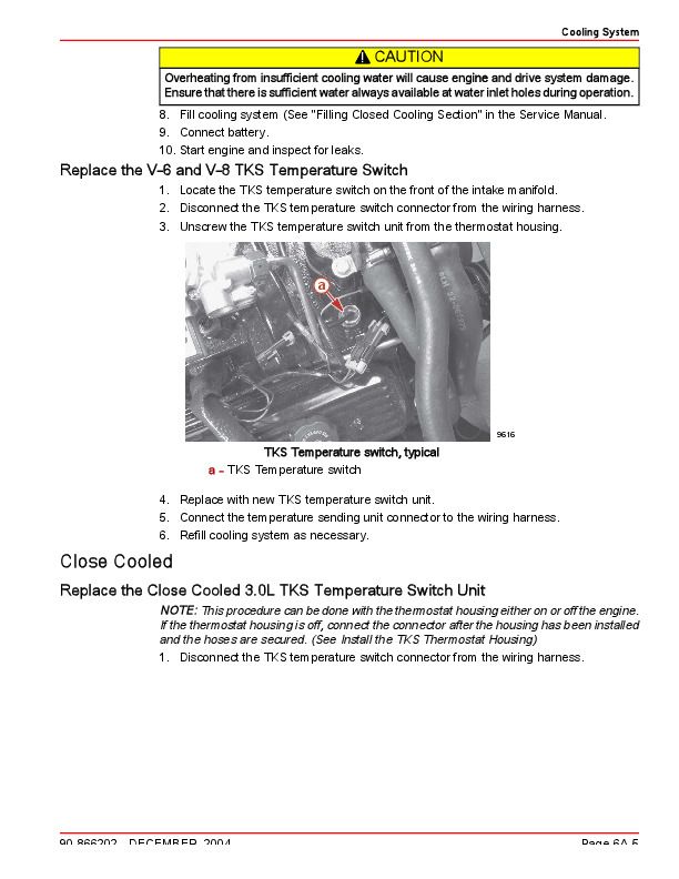
MERCRUISER AND MERCURY RACING (STERNDRIVE) OUTBOARDS SERVICE MANUAL INDEX
00 Index.pdf
01. 1963-1973 Engines & Drives (#9068648).pdf
02. 1974-1977 Engines, Drives & Jet Drive 400 (#9071707).pdf
03. 1978-1984 Engines.. 4-Cylinder, L6 &V8 (#9095693R1).pdf
04. 1978-1982 Sterndrives.. MC 120 to 260 (#9086137).pdf
05. 1978-1993 Sterndrives.. TR & TRS (#9012935).pdf
06. 1983-1990 Sterndrives.. R, MR, Alpha One & Alpha One SS (#90129342).pdf
07. 1983-1993 Engines.. GM V6 (#9012410).pdf
08. 1985-1999 Engines.. MM 4-Cylinder (#9044553R2).pdf
09. 1985-1988 Engines.. GM V8 (#9014499R1).pdf
10. 1985-1989 Engines.. GM 4-Cylinder (#90146931R1).pdf
11. 1988-1998 Sterndrives.. Bravo (#90174314).pdf
13. 1990-1997 Engines.. GM 4-Cylinder (#90816462R2).pdf
14. 1991-2008 Sterndrives.. Alpha One Gen II (#908181773).pdf
15. 1989-1992 Engines.. GM V8 (#90816463).pdf
16. 1993-1997 Engines.. GM V8 454cid & 502cid (#908232242).pdf
17. 1993-1997 Engines.. GM V8 5.0L, 454cid & 502cid (#908232251).pdf
18. 1993-1997 Engines.. GM V6 Gen II Balance Shaft (#908232261).pdf
22. 1997-2008 Engines.. D-Tronic 2.8L & 4.2L (DI) Diesel (#908600741).pdf
23. 1998-2001 Engines.. GM V8 Gen VI & L29 (454cid & 502cid) (#908613261).pdf
24. 1998-2001 Engines.. GM V8 305cid & 350cid (#908613271).pdf
24-S. 2000-2001 Engines.. GM V8 377cid (6.2L) (Supplement to #24) (#90861327000).pdf
25. 1998-2001 Engines.. GM V6 262cid (4.3L) (#908613281).pdf
26. 1998-2001 Engines.. GM 4-Cylinder 181cid (3.0L) (#908613291).pdf
27. 1998-2002 Engines.. V8 D7.3L D-Tronic (DI) Diesel (#90861784).pdf
27-S. 1998-2002 Engines.. V8 D7.3L D-Tronic, D-Tronic LD (DI) Diesel (#90861784990).pdf
28. 2000-2005 Sterndrives.. Bravo 1-2-3 & XZ-XR and Sport Master (#908631601).pdf
29. 2000-2008 Engines.. Sterndrive D1.7L DTI In-Line Diesel (#90863016).pdf
30. 2000-2008 Engines.. 496cid (8.1L) Gasoline Engine (#90863161).pdf
31. 2001-2008 Engines.. 305cid (5.1L), 350cid (5.7L) & 377cid (6.2L) (#90864260001).pdf
32. 2001-2008 Engines.. Sterndrive 4.3L MPI (#90864261).pdf
33. 2001-2008 PCM 555 Diagnostics (#90863757002).pdf
36. 2006-2008 ECM 555 Diagnostics (#90864573001).pdf
37. 2002-2008 Engines.. Dry Joint Exhaust System (Supplement to #31) (#90864260020).pdf
40. 2004-2008 Engines.. Gen III Cool Fuel (Supplement to #30, #31) (#90865376).pdf
41. 2004-2008 Engines.. Turn Key Start (TKS) Carburetors (Supplement to #25, #26, & #31) (#90866202).pdf
90-8M0082470 - 200/225/250/275/300 250 & 300 Pro 300 CCT Verado FourStroke Service Manual (2005&up).pdf
90-8M0082470 - 200_225_250_275_300 250 & 300 Pro 300 CCT Verado FourStroke Service Manual (2005&up)...3
cover...3
notice.pdf...0
Notice to Users of This Manual...4
Precautions...4
Replacement Parts...5
Cleanliness and Care of Product...5
Manual Outline...6
1A...8
Section 1A - Master Specifications...8
Table of Contents...8
200/225/250/275/300 Verado Master Specifications...9
General Specifications...9
Fuel System Specifications...10
Ignition Specifications...10
Charging and Starting Specifications...11
Cylinder Head Specifications...12
Cylinder Block/Crankcase Specifications...13
Power Trim Specifications...13
Oil System Specifications...14
Gear Housing Specifications (Standard Rotation)...14
Gear Housing Specifications (Counter Rotation)...15
Gear Housing Specifications–5.44 in. Diameter Gearcase Torpedo...15
Power Steering Specifications...16
Propeller Chart...16
Mercury/Mariner 200 (6 Cyl., FourStroke) with 4.8 in. Gearcase Torpedo...16
Mercury/Mariner 225 (6 Cyl., FourStroke) with 4.8 in. Gearcase Torpedo...18
Mercury/Mariner 225 (6 Cyl., FourStroke) with 5.44 in. Gearcase Torpedo...20
Mercury/Mariner 250 (6 Cyl., FourStroke) with 4.8 in. Gearcase Torpedo...21
Mercury/Mariner 250 Pro (6 Cyl., FourStroke) with 4.8 in. Gearcase Torpedo...23
Mercury/Mariner 250 (6 Cyl., FourStroke) with 5.44 in. Gearcase Torpedo...25
Mercury/Mariner 275 (6 Cyl., FourStroke) with 4.8 in. Gearcase Torpedo...27
Mercury/Mariner 300 (6 Cyl., FourStroke) with 4.8 in. Gearcase Torpedo...29
Mercury/Mariner Pro 300 (6 Cyl., FourStroke) with 4.8 in. Gearcase Torpedo...30
Mercury/Mariner 300 (6 Cyl., FourStroke) with 5.44 in. Gearcase Torpedo...32
Mercury/Mariner 300 HD (6 Cyl., FourStroke) with 5.44 in. Gearcase Torpedo...34
1B...38
Section 1B - Maintenance...38
Table of Contents...38
Outboard Care...40
Selecting Replacement Parts For Your Outboard...40
EPA Regulations...40
EPA Emissions...40
Emission Certification Label...40
Owner Responsibility...40
Inspection and Maintenance Schedule...40
Before Each Use...40
After Each Use...40
Every 100 Hours of Use or Once Yearly, Whichever Occurs First...41
Every 300 Hours of Use or Three Years...41
Before Periods of Storage...41
Flushing the Cooling System...41
Cowl Removal and Installation...42
Cowl Removal...42
Cowl Installation...42
Exterior Care...43
Cleaning Care for Top and Bottom Cowls...43
Cleaning Care for the Powerhead in Saltwater Use...43
Battery Inspection ...43
Verado Engine Battery Specifications...44
Air Filter...45
Air Filter Removal and Cleaning...45
Air Filter Installation...46
Closed Compartment Technology...46
Cowl Removal and Installation...46
Air Duct Removal...46
Cowl Removal...47
Cowl Installation...47
Air Duct Installation...48
Idle Relief Hose Connection...49
Removal...49
Installation...50
Intake Air Filter...50
Air Filter Removal...50
Air Filter Installation...50
K & N Air Filter Maintenance...51
Flushing the Cooling System...51
Fuel System...51
Fuel Line Inspection...51
Water Separating Fuel Filter...51
Filter Removal...51
Filter Draining...53
Filter Installation...53
Corrosion Control Anode...53
Propeller Replacement...54
Spark Plug Inspection and Replacement...55
Fuses...56
DTS Wiring System...57
Accessory Drive Belt Inspection...57
Checking Power Trim Fluid...57
Checking Power Steering Fluid...58
Checking and Adding Engine Oil...58
Changing Engine Oil ...59
Engine Oil Capacity...59
Pump Method...59
Drain Method...59
Changing Oil Filter ...60
Oil Filling...60
Gearcase Lubrication...61
...
4A...366
Section 4A - Cylinder Block/Crankcase...366
Table of Contents...366
Cylinder Block/Crankcase Specifications...367
Port Cylinder Block Components...371
Starboard Cylinder Block/Oil Cooler (S/N 1B830815 and Below)...373
Starboard Cylinder Block/Oil Cooler (S/N 1B830816 and Above)...377
Cylinder Block Components...381
Crankshaft, Piston, and Connecting Rod Components (Design I)...383
Crankshaft, Piston, and Connecting Rod Components (Design II)...385
Powerhead Removal...387
Removing Powerhead Components...398
Engine Harness Bracket...398
Integrated Oil Module (IOM)...399
Starter...400
Purge Line...401
Induction System...401
Alternator Support Bracket and Knock Sensor...406
Injector/Coil Harness...406
Oil Pressure/Temperature Sensor...407
Electrical Box...407
Thermostat Housing...408
Thermostat Removal...408
Ignition Coil...409
Powerhead Disassembly...409
Cylinder Head Removal ...409
Flywheel...412
Crankcase and Crankshaft Disassembly/Removal...413
Cleaning, Inspection, and Repair...415
Measuring Cylinder Bore...415
Measuring Piston...416
Piston Diameter...416
Piston Ring Groove...417
Piston Ring Side Clearance...417
Piston Ring End Gap...417
Piston Wrist Pin Diameter...418
Piston Wrist Pin...418
Measuring Connecting Rod ...419
Measuring Crankshaft...419
Crankshaft Runout...419
Crankshaft Main Bearing and Crankpin Measurement...420
Powerhead Assembly...420
Powerhead Preassembly Cleaning Recommendations...420
Installing Water and Oil Jacket Plugs...420
Selecting New Crankshaft Bearings...421
Crankshaft Main Bearing Grade Selection...422
Piston/Connecting Rod Assembly...423
Connecting Rod Bearing Grade Selection...423
Piston Ring Installation...425
Piston Assembly Installation...427
Cylinder Head Installation...429
Timing Chain...432
Installing the Upper Crankshaft Seal...436
Preparation...436
New Crankshaft Installation...437
Original Crankshaft Installation...438
Installing Powerhead Components...439
Ignition Coil...439
Crankshaft Position Sensor Installation...439
Flywheel Installation...440
Thermostat...441
Thermostat Installation...441
Thermostat Housing Installation...442
Electrical Box...442
Oil Pressure/Temperature Sensors...443
Injector/Coil Harness...444
Alternator Support and Knock Sensors...445
Induction System...446
Purge Line...451
Starter...452
Integrated Oil Module (IOM)...453
Engine Harness Bracket...454
Alternator...455
Alternator/Supercharger Belt...456
After Servicing Engine...456
Dressed Powerhead Installation...459
4B...474
Section 4B - Cylinder Head...474
Table of Contents...474
Cylinder Head Specifications...475
Cylinder Head Components (S/N 1B517433 and Below)...477
Cylinder Head Components (S/N 1B517434–1B733951)...481
Cylinder Head Components (S/N 1B733952 and Above)...485
Cylinder Head Service Recommendations...489
Cylinder Head Disassembly...489
Camshaft Removal...489
Valve Removal...489
Cylinder Head Galley Plug Removal...490
Cleaning/Inspection/Repair ...491
Camshaft...491
Valves...492
Valve Springs...493
Cylinder Head...493
Valve Guides...493
Valve Guide Replacement...494
Valve Seat Reconditioning...494
Cylinder Head Reassembly...495
Cylinder Head Galley Plug Installation...495
Valves...495
Cams...497
Valve Clearance and Adjustments...498
Valve Clearance Measurement Steps...498
Changing Valve Clearance...498
4C...500
Section 4C - Lubrication...500
Table of Contents...500
Oil System Specifications...501
Starboard Cylinder Block/Oil Cooler (S/N 1B830815 and Below)...503
Starboard Cylinder Block/Oil Cooler (S/N 1B830816 and Above)...507
Oil Pump and Adapter Plate Components (S/N 1B517433 and Below)...511
Oil Pump and Adapter Plate Components (S/N 1B517434 and Above)...513
Engine Guardian System...515
Low Oil Pressure, Engine Guardian...515
Oil Pump Removal ...515
Oil Pump Installation...516
Integrated Oil Module (IOM)...518
IOM Removal...518
IOM Disassembly...518
IOM Assembly...519
IOM Installation...521
5A...522
Section 5A - Pedestal/Mount Cradle and Driveshaft Housing...522
Table of Contents...522
Mount Cradle Components...525
Pedestal/Power Trim/Steering Cylinder Components...527
Driveshaft Housing Components (S/N 1B229697 and Below)...531
Driveshaft Housing Components (S/N 1B229698 and Above)...533
Top Cowl Components...535
CCT Top Cowl Components...537
Rear Cowl Components...539
CCT Rear Cowl Components...541
Cowl Latching Components...543
CCT Rigging Components...545
Water Poppet Removal/Installation...547
Removal and Disassembly...547
Reassembly and Installation...547
Midsection Disassembly...549
Preparing Outboard for Midsection Disassembly...549
Fuel Supply Module (FSM)...549
Hoses and Harnesses...550
Driveshaft Housing...551
Pedestal...552
Mount Cradle Removal...552
Power Trim System Removal...553
Pedestal Bearings and Seals...554
Steering Tube...556
Mount Cradle...556
Cowl Latches...556
Seal...557
Rear Motor Mounts...557
Tilt Lock...557
Midsection Assembly...560
Mount Cradle...560
Rear Motor Mounts...560
Tilt Lock...560
Seal...563
Adapter Plate...563
Pedestal...563
Steering Tube...563
Bearings and Seals...564
Power Trim System...566
Mount Cradle Tilt Pin...568
Cowl Side Latches...569
Power Trim Harness...569
Trim Cylinder Rod Ends...570
Hoses and Harnesses...570
Driveshaft Housing...571
Fuel Supply Module (FSM)...572
Completing Mid-Section Reassembly...574
5B...576
Section 5B - Adapter Plate...576
Table of Contents...576
Upper Shift Components...579
Oil Pump/Adapter Plate - Upper Components (S/N 1B517433 and Below)...581
Oil Pump/Adapter Plate - Upper Components (S/N 1B517434 and Above)...585
Adapter Plate - Lower Components...589
Adapter Plate Hose Routings Components...591
CCT Adapter Plate Hose Routings Components...593
CCT Idle Exhaust Relief Hose Routing...595
Adapter Plate Disassembly...595
Preparing Outboard for Adapter Plate Disassembly...595
Exhaust Tube and Oil Sump...595
Adapter Plate...596
Lower Components...596
Removing from Mount Cradle...596
Front Bracket Disassembly...598
Upper Components...600
Oil Pump...602
Driveshaft Seals...602
Adapter Plate Reassembly...602
Dowel Pins and Plugs...602
Driveshaft Seals...603
Oil Pump...604
Upper Components...604
Front Bracket Reassembly...606
Motor Mounts...606
Grommets and Bushings...607
Mounting...607
Shift Components...608
Adapter Plate to Mount Cradle Seal...609
Installing in Mount Cradle...611
Lower Components...613
Exhaust Tube/Oil Sump...614
Completing Outboard Adapter Plate Reassembly ...616
5C...618
Section 5C - Power Trim...618
Table of Contents...618
Power Trim Specifications...619
Power Trim System Components...621
Power Trim Cylinder Components...623
Pressure Operated Check Manifold Components...624
Power Trim and Tilt...624
Power Trim Operation...625
Tilting To Full Up Position...625
Tilt At Helm...625
Tilt At Engine...625
Trailering Boat/Outboard ...626
Manual Tilting...627
Auxiliary Tilt Switch...627
Shallow Water Operation...627
Check Fluid and Purge the Power Trim System...628
Checking Power Trim Fluid...628
Purging Power Trim System...628
Theory of Operation...629
Power Trim Hydraulic Diagram...629
Operation...630
Trim Circuit - Up...630
Trim Circuit - Down...630
Trail Over System...630
Troubleshooting the Power Trim System...630
Preliminary...630
Hydraulic System Troubleshooting...631
Condition/Problem...631
Problem/Solution...631
Testing Power Trim System...631
Install Test Gauge Adapter Fitting for Up Pressure Test...631
Up Pressure Circuit Test...633
Install Test Gauge Adapter Fitting for Down Pressure Test...634
Down Pressure Circuit Test...635
Electrical System Troubleshooting...636
General Checks...636
Condition/Problem...636
Problem/Solution...636
Power Trim Relay Test Procedure...636
Power Trim Electrical Circuit...639
Troubleshooting the Down Circuit...640
Troubleshooting the Up Circuit...640
Troubleshooting the Down and Up Circuits (All Circuits Inoperative)...641
Trim Position Sensor...642
Troubleshooting the Trim Position Circuit...642
Trim Position Senor Resistance Table...644
Breakout Box Connections...644
Trim Position Sensor Location...644
General Service Recommendations...644
Seals...645
Power Trim System...645
Power Trim System Removal...645
Power Trim Harness...645
Trim Cylinder Rod Ends...646
Power Trim Assembly...647
Power Trim System Installation...648
Power Trim Harness...650
Trim Cylinder Rod Ends...651
Purging the Power Trim System...653
Power Unit...653
Power Unit Disassembly...653
Draining the System...654
Reservoir...654
Pump and Filter...656
Power Unit Reassembly...656
Pump and Filter ...657
Trim Motor...657
Reservoir...658
Filling and Purging System...659
Trim Cylinder and Pivot Pin...660
Trim Cylinder and Pivot Pin Removal...660
Disassembly...660
Trim Cylinder Disassembly...662
Cylinder Rod...662
Shock Piston...662
End Cap...664
Memory Piston...665
Trim Cylinder Reassembly...665
Memory Piston...665
End Cap...666
Shock Piston and Cylinder Rod...667
Trim Cylinder and Pivot Pin Installation...669
System Installation...671
Pressure Operated Check Manifold ...672
Manifold Disassembly...672
Removing and Draining the Power Trim System...672
Manual Release Valve...672
Pressure Operated Check Valve...672
Manifold Reassembly...673
System Installation...674
6A...676
Section 6A - Right-Hand Rotation (4.8 in. Diameter)...676
Table of Contents...676
Gear Housing Specifications (Standard Rotation)...677
Gear Housing (Driveshaft)...683
Gear Housing (Propeller Shaft) (Standard Rotation)...687
General Service Recommendations...690
Bearings...690
Shims...690
Seals...690
Gearcase Removal...690
Gearcase Serviceability Inspection...692
Draining and Inspecting Gear Housing Lubricant...692
Propeller Shaft Inspection...693
Water Pump...693
Removal and Disassembly...693
Cleaning and Inspection...694
Oil Seal Carrier Assembly...695
Removal...695
Disassembly...695
Reassembly...696
Bearing Carrier and Propeller Shaft...697
Cleaning/Inspection...699
Disassembly...700
Assembly...701
Driveshaft Assembly...704
Removal...704
Disassembly...707
Inspection...707
Assembly...708
Propeller Shaft Assembly and Forward Gear Bearing Cup...709
Removal...709
Component Disassembly...710
Inspection...711
Forward Gear Assembly...712
Component Inspection...712
Disassembly...712
Assembly...714
Shift Spool Assembly...714
Inspection...714
Disassembly...715
Reassembly...715
Propeller Shaft Reassembly...716
Shift Shaft Assembly...717
Removal...717
Disassembly and Inspection...717
Assembly...718
Pinion Bearing Removal...720
Gear Housing Inspection...720
Pinion Bearing Installation...721
Forward Bearing Cup...722
Installation...722
Shift Shaft Installation...722
Propeller Shaft Installation...723
Driveshaft and Pinion Gear Installation...724
Pinion Gear Height...726
Checking and Adjusting Using Pinion Gear Locating Tool 91-56048001...726
Checking and Adjusting using Pinion Gear Locating Tool 91-12349A05...727
Forward Gear Backlash...728
Reverse Gear Backlash...730
Propeller Shaft Bearing Preload...731
Bearing Carrier Final Installation...733
Oil Seal Carrier Installation...734
Water Pump Installation...735
Checking Gearcase Operation...737
Gear Lubricant Filling Instructions...737
Installing Gear Housing to Driveshaft Housing...737
6B...740
Section 6B - Left-Hand Rotation (4.8 in. Diameter)...740
Table of Contents...740
Gear Housing Specifications (Counter Rotation)...741
Gear Housing (Driveshaft)...747
Gear Housing (Propeller Shaft) (Counter Rotation)...751
General Service Recommendations...754
Bearings...754
Shims...754
Seals...754
Gearcase Removal...754
Gearcase Serviceability Inspection...756
Draining and Inspecting Gear Housing Lubricant...756
Propeller Shaft Inspection...757
Water Pump...757
Removal and Disassembly...757
Cleaning and Inspection...758
Oil Seal Carrier Assembly...759
Removal...759
Disassembly...759
Reassembly...760
Bearing Carrier and Propeller Shaft...761
Removal...761
Cleaning/Inspection...763
Disassembly...764
Assembly...767
Driveshaft Assembly...770
Removal...770
Disassembly...773
Inspection...773
Reassembly...774
Propeller Shaft Assembly and Reverse Gear Bearing Cup...775
Removal...775
Disassembly...776
Inspection...776
Reverse Gear Assembly...777
Inspection...777
Disassembly...778
Assembly...779
Shift Spool Assembly...779
Inspection...779
Disassembly...780
Reassembly...780
Propeller Shaft Reassembly...781
Shift Shaft Assembly...782
Removal...782
Disassembly and Inspection...782
Assembly...783
Pinion Bearing Removal...784
Gear Housing Inspection...785
Pinion Bearing Installation...786
Reverse Gear Bearing Cup...787
Installation...787
Shift Shaft Installation...787
Propeller Shaft Installation...789
Driveshaft and Pinion Gear Installation...789
Pinion Gear Height...792
Checking and Adjusting using Pinion Height Tool 91-56048001...792
Checking and Adjusting using Pinion Gear Locating Tool 91-12349A05...793
Bearing Carrier Installation...794
Reverse Gear Backlash...794
Forward Gear Backlash...796
Propeller Shaft Bearing Preload...797
Bearing Carrier Final Installation...798
Oil Seal Carrier Installation...799
Water Pump Installation...800
Checking Gearcase Operation...802
Gear Lubricant Filling Instructions...802
Installing Gear Housing to Driveshaft Housing...803
6C...806
Section 6C - Right-Hand and Left-Hand Rotation (5.44 in. Diameter)...806
Table of Contents...806
Gear Housing Specifications...807
Gear Housing Components...815
Gear Housing (Driveshaft)...815
Gear Housing (Propeller Shaft)...819
General Service Recommendations...821
Bearings...821
Shims...821
Seals...821
Gearcase Serviceability Inspection...821
Draining and Inspecting Gear Housing Lubricant...821
Propeller Shaft Inspection...822
Gearcase Removal...823
Water Pump Removal...825
Removal and Disassembly...825
Cleaning and Inspection...825
Oil Seal Carrier Assembly...826
Removal...826
Disassembly...826
Bearing Carrier and Propeller Shaft...827
Cleaning/Inspection...829
Disassembly...831
Assembly...833
Driveshaft Removal, Inspection, Disassembly, and Assembly...836
Driveshaft Removal...836
Driveshaft Inspection...838
Driveshaft Disassembly...839
Driveshaft Assembly...839
Propeller Shaft Assembly and Front Gear Bearing Cup...841
Removal...841
Component Disassembly...842
Inspection...843
Front Gear Assembly...844
Component Inspection...844
Disassembly...844
Assembly...845
Shift Spool Assembly...846
Inspection...846
Disassembly...846
Reassembly...847
Propeller Shaft Assembly...847
Shift Shaft Cover Assembly...848
Removal...848
Disassembly and Inspection...849
Assembly...850
Pinion Bearing Removal...851
Gear Housing Inspection...852
Pinion Bearing Installation...853
Front Gear Bearing Cup Installation...854
Shift Shaft Installation...854
Propeller Shaft Installation...855
Driveshaft and Pinion Gear Installation...856
Pinion Gear Height...858
Checking and Adjusting using Pinion Gear Locating Tool 91-8M0046443...858
Front Gear Backlash...859
Rear Gear Backlash...862
Propeller Shaft Bearing Preload (Design I and Design II)...863
Propeller Shaft Assembly - Design I...863
Propeller Shaft Assembly - Design II...863
Preload Procedure...863
Bearing Carrier Final Installation...865
Oil Seal Carrier Installation...868
Water Pump Installation...868
Checking Gear Housing Operation...871
Standard Rotation...871
Counterrotation...871
Gear Housing Installation...872
Gear Lubricant Filling Instructions...874
7A...876
Section 7A - Attachments...876
Table of Contents...876
Dual Tie Bar...877
Installation...877
Maintenance Instructions...881
Plus One Tie Bar...881
Installation...881
Maintenance Instructions...885
Rudder Sensor Installation Instructions...886
Rudder Sensor Installation...886
Magnet Installation...887
Wire Connections...888
Liquid Tie Bar...888
Liquid Tie Bar Installation...888
Bleeding Instructions...889
Realignment Instructions...890
Propellers too Far Apart...890
Propellers too Close Together...891
Power Steering...891
Power Steering Primer Module...891
Filling Power Steering System with Engine Not Running...892
Adapter Steering Arm - Kicker Engine...893
Installation Instructions...893
Analog Gauge Interface (AGI)...894
Wire Color Code Abbreviations...894
Analog Gauge Interface (AGI) Installation...894
Typical AGI Application with System View...895
Configuring Analog/Digital Tachometer Signal through PCM...896
PCM Configuration with CDS...896
8A...898
Section 8A - Power Steering...898
Table of Contents...898
Power Steering Specifications...899
Power Steering Cylinder Components...901
Power Steering Systems...903
Single Helm - Single Cylinder...903
Dual Helm - Single Cylinder...904
Dual Station Steering Helm Identification...904
Single Helm - Dual Cylinder...905
Dual Helm - Dual Cylinder...906
Dual Station Steering Helm Identification...906
Troubleshooting the Power Steering System...907
Testing the Power Steering Driver Module...907
Power Steering Cylinder...908
Steering Cylinder...908
Removal...908
Installation...909
Steering Cylinder Service...910
Power Steering Installation...911
Power Steering System...911
Installation Procedure...911
Selecting Location for the Power Steering Pump...911
Required Mounting Clearances for the Power Steering Pump...912
Installing Power Steering Pump...912
Connection of the Hydraulic Hoses to the Steering Helm...912
Connection of the Hydraulic Hoses to the Power Steering Pump...914
Connection of the Hydraulic Hoses to the Steering Cylinder...916
Electrical Connections to the Steering Pump...917
Filling Power Steering System with Engine Not Running...918
Filling Power Steering System with Engine Running...920
Routing Connections Through the Cowl...921
9A...922
Section 9A - Color Diagrams...922
Table of Contents...922
200/225/250/275 Verado Engine Harness S/N 0T980000–1B229688...925
200/225/250/275/300 Verado Engine Harness S/N 1B229689 and above...928
200/225/250/275 Verado Oil Flow Diagram S/N 0T980000–1B517433...931
200/225/250/275/300 Verado Oil Flow Diagram S/N 1B517434 and Above...934
200/225/250/275/300 Verado Water Flow Diagram S/N 0T980000 and Above...935
200/225/250/275/300 Verado Fuel Flow Diagram S/N 0T980000 and Above...938
Index...940
MerCruiser and Mercury Racing (Sterndrive) Service Manual Index...940
...940
Mercury MerCruiser...940
Mercury Racing Sterndrives...944
Service Manual #01...946
Models Covered...950
Section 1-General Information...0
A-General Information...953
B-Tuneup...979
C-Lubrication...993
Section 2-Removal-Installation-Alignment...0
A-Mercruiser 60-80-90...1013
B-MerCruiser I Early...1025
C-MerCruiser II Early...1043
D-MerCruiser II Transom...1059
E-MerCruiser III...1071
F-MerCruiser 215H...1079
G-MerCruiser 215E...1089
H-888 Sterndrive...1101
J-MerCruiser II-TR Drive Unit...1113
Secton 3-Electrical Systems...0
A-Starting System...1125
B-Ignition System...1157
C-Alternator System...1193
D-Instrumentations...1219
E-Wiring Diagrams...1221
Section 4-Fuel Systems...0
A-Fuel Pumps...1261
B-Carburetors...1277
Section 5-Engine...0
A-Inline GM Engine Mechanical...1353
B. In-Line 60-80-90-Engine Mechanical...1387
C-V-8 GM Engine Mechanical...1415
D-V-8 Ford Engine Mechanical...1455
Section 6-Drive Systems...0
A-MerCruiser 60-80-90 & MerCruiser I...1495
B-MerCruiser II...1553
C-MerCruiser 215...1595
D-MerCruiser III...1595
E-Direct Drive Transmission...1615
F-MerCruiser II-TR Drive Unit...1659
G-MerCruiser II-TR Drive Unit...1685
Section 7-Accessories...0
A-Power Tilt & Trim...1707
B-Steering System...1743
C-Remote Controls...1769
D-Cooling...1799
E-General Accessories...1827
Section 8-Specifications...1841
Section 9-Tools...1881
Service Manual #02...1921
Models Covered...1924
Section 1-General Information...0
A-General Information...1929
B-Tuneup...1945
C-Lubrication...1955
Section 2-Removal/Installation/Alignment...0
A-MerCruiser 120-140-165-470...1967
B-MerCruiser V-8 I-Drive Models...1979
C-MerCruiser II-TR & II-TRS Sterndrive...1993
D-General Installation...2005
Section 3-Electrical System...0
A-Starting System...2019
B-Ignition System...2041
C-Alternator System...2063
D-Instrumentation...2095
E-Wiring Diagrams...2109
Section 4-Fuel System...0
A-Fuel Pumps...2135
B-Carburetors...2141
Section 5-Engine...0
A-Engine Mechanical In-Line...2179
B-Engine Mechanical V8 Ford...2213
C-Engine Mechanical V8 GM...2251
D-Engine Mechanical 470 Model...2283
Section 6-Drive Systems...0
A-MerCruiser I Drive Unit...2317
B-MerCruiser II-TR Drive Unit...2365
C-MerCruiser II-TRS Drive Unit...2395
D-Direct Drive Transmission...2409
E-MerCruiser II_TR & II-TRS Transmission...2431
Section 7-Accessories...0
A-Power Trim System...2451
B-Steering Systems...2471
C-Remote Controls...2485
D-Cooling ...2515
E-General Accessories...2575
Section 8-Specifications...0
A-Tune-Up & General...2585
B-Internal Engine...2619
C-Torque Specs...2629
D-Propeller Chart...2643
Section 9-400 Jet Drive...2644
Section 10-Troubleshooting...2680
Service Manual #03...2756
Models Covered...2758
Section 1-Important Information/Troubleshooting...0
A-General Information...2762
B-Maintenance...2780
C-Troubleshooting...2820
Section 2-Removal/Installation/Alignment...0
A-MCM 120/140/165...2848
B-MCM 120R/140R Driveshaft Extension Models...2858
C-MCM 470/485/488...2870
D-MCM 898/228/260...2880
E-MCM 898/228/260 Driveshaft Ext. Models...2890
F-MCM 330TR/TRS w/Mercury Transmission...2904
G-MCM 330 (B-W) TR/TRS...2914
H-MCM 370/400TRS & Hi-Perf Engines...2924
I-Mie 470/228/230/255/260/330/340...2938
Section 3-Electrical System...0
A-Starting System...2952
B-Ignition System...2974
C-Charging System...3014
D-Instrumentation...3074
E-Electrical Kits...3084
F-Wiring Diagrams...3118
Section 4-Fuel System...0
A-Fuel Delivery System & Fuel Pumps...3206
B-Rochester 2 Barrel...3222
C-MerCarb 2 Barrel...3252
D-Rochester 4 Barrel...3280
E-Holley 4 Barrel...3318
Section 5-Exhaust System...0
A-Exhaust Manifolds/Elbows...3342
B-Exhaust Risers...3360
C-Exhaust Collectors...3376
Section 6-Engine...0
A-GM In-Line...3402
B-Mercury Marine 4 Cylinder...3442
C-GM V8...3496
Section 7-Cooling System...0
A-Seawater Cooled Models...3600
B-470/485/488...3648
C-Closed Cooled Models...3682
Section 8-Drive Systems...0
A-Velvet Drive (Borg-Warner)...3722
B-Mercury Marine Transmission...3746
C-Driveshaft Models/Propeller Shaft...3800
Section 9-Power Steering System...3810
Service Manual #04...3848
Models Covered...3850
Section 1-General Information...3854
Section 2-Troubleshooting...3866
Section 3- Drive Unit...0
A-Driveshaft Housing Assembly...3883
B-Gear Housing Assembly...3908
Section 4-Transom Plate Assembly...3934
Section 5-Power Trim...3975
Section 6-Power Steering...4017
Section 7-Service Bulletins...4046
Service Manual #05...4078
Models Covered...4084
Section 1 - Important Information...0
A - Important Information...4082
B - Maintenance...4088
C - Basic Cleaning and Inspection...4098
D - Power Package Layup & Recommissioning...4102
E - Propellers...4106
F - Troubleshooting...4132
Section 2 - Removal, Installation and Adjustments...0
A - All Models...4140
Section 3 - Sterndrive Unit...0
A - General Information...4180
B - Driveshaft Housing...4186
C - Gear Housing...4210
Section 4 - Transom Assembly...0
A - All Models...4240
Section 5 - Power Trim...0
A - Oilydne Power...4272
B - Prestolite Low Pressure Power Trimp Pump...4306
C - Prestolite High Pressure Power Trim Pump...4328
D - Trim Cylinders...4352
E - Dual Power Trim Control...4364
Section 6 - Steering Systems...0
A-Power Steering...4370
Service Manual #06...4404
Models Covered in This Manual ...4406
Section 1 - Important Information...0
A - Important Information...4411
B - Maintenance...4417
C - Troubleshooting...4435
Section 2 - Removal, Installation and Adjustments...0
A - All Models...4483
Section 3 - Sterndrive Unit...0
A - Drive Shaft Housing...4509
B - Gear Housing - MR/Alpha One/Alpha One SS...4545
C - Gear Housing - I-R...4601
D - Gear Housing - Alpha One Counter Rotation...4648
Section 4 - Transom Assembly...0
A - Service Procedures Requiring Minor...4713
B - Service Procedures Requiring Major Disassembly...4739
Section 5 - Power Trim...0
A - Oildyne Power Trim Pump (Plastic Reservoir)...4779
B - Oildyne Power Trim Pump (Aluminum Reservoir)...4815
C - Prestolite Power Trim Pump...4851
D - Trim Cylinders...4877
E - Dual Power Trim Control...4887
F - Auto Trim II...4895
Section 6 - Steering Systems...0
A - Power Steering...4904
B - Manual Steering...4944
Section 7 - Corrosion Protection...0
All Models...4952
Service Manual #07...4970
7cov...4970
Models Covered...4972
Section 1-Important Information...4977
A-General Information...4977
B-Maintenance...4988
C-Troubleshooting...5004
sec2...5030
Section 2-Removal & Installation...0
A-MCM 185 (229 cid)...5030
B-MCM 175,185,205 43L, 4.3LX...5043
sec3...5059
Section 3-Engine Mechancial...0
B-185-205 (262 cid) 4.3L...5108
sec4...5157
Section 4-Electrical...0
A-Starting System...5157
B-Ignition System...5179
C-Charging System...5199
D-Instrumentation...5234
E-Wiring Diagrams...5243
Section 6-Closed Cooling...0
C-Exhaust System...5157
sec5...5257
Section 2-Removal & Installation...5257
Section 3-Engine Mechancial...5257
Section 5-Fuel System...5257
A-Fuel Delivery...5257
B-Fuel Pump...5263
C-2 BBL Mercarb...5272
D-4 BBL Rochester Carburetor...5300
E-4 BBL Weber Carburetor...5331
sec6...5362
Section 6-Closed Cooling...0
A-Standard Cooling...5362
B-Closed Cooling...5372
C-Exhaust System...5384
sec7...5392
Section 7-Power Steering...0
A-Power Steering...5392
Service Manual #08...5407
Models Covered...5409
Section 1-Important Information...0
A-Important Information...5413
B-Maintenance...5421
C-Troubleshooting...5437
Section 2-Removal & Installation...0
A-4 Cyl.3.7L (224cid)...5463
Section 3-Engine Mechanical...0
A-4 Cyl.3.7L (224cid)...5473
Section 4-Electrical Systems...0
A-Starting System...5515
B-Ignition System...5531
C-Charging Systems...5553
D-Instrumentation...5567
E-Wiring Diagrams...5577
Section 5-Fuel Systems...0
A-Fuel Delivery System...5587
B-Fuel Pump...5591
C-Carburetor...5597
Section 6-Cooling & Exhaust...0
A-Cooling System...5647
B-Exhaust System...5663
Section 7-Power Steering...0
A-Power Steering...5669
Service Manual #09...5681
Models Covered...5682
Sec1 Important Information...0
A-Important Information...5684
B-Maintenance...5696
C-Troubleshooting...5723
Sec 2 Removal & Installation...0
A-MCM Models with I Drive...5766
B-MCM Models w/I Drive w/Driveshaft Ext...5774
C-330 (B-W) TR-TRS...5786
D-MCM Models TR/TRS Drives...5794
E-MIE Models /5.7 Ski...5805
F-MCM Models w/Bravo Drive...5818
Sec 3 Engine...0
A-V8 GM (305/350cid)...5825
B-V8 (454/482/540 cid)...5892
Sec 4 Electrical System...0
A-Starting System...5966
B-Ignition System...5979
C-Charging System...5999
D-Instrumentation...6050
E-Electrical Kits...6060
F-Wiring Diagrams...6072
Sec 5 Fuel System...0
A-Fuel Delivery System & Fuel Pumps...6112
B-MerCarb 2 Barrel...6122
C-Rochester 4 Barrel...6149
D-Holley 4 Barrel (Model 4150)...6181
E-Holley 4 Barrel (Model 4500)...6201
F-Fuel Injectors/Fuel Rails...6220
Sec 6 Cooling System...0
A-Seawater Cooled Models...6224
B-Closed Cooled Models...6264
Sec 7 Exhaust System...0
A-General Information...6286
B-Exhaust Manifolds/Elbows...6291
C-Exhaust Risers...6299
D-Exhaust Collectors...6308
Sec 8 Drive Systems...0
A-Velvet Drive (Borg Warner) Transmission...6317
B-Driveshaft Models/Propeller Shaft...6338
C-Hurth Transmission...6347
Sec 9 Power Steering...0
A-Power Steering...6392
Service Manual #10...6404
Service Manual #11...6712
Service Manual #13...7308
Models Covered In This Manual...7312
Section 1 - Importnt Information...0
A - General Information...7314
B - Maintenance...7322
C - Troubleshooting...7343
Section 2 - Removal and Installation...0
A - 4 Cylinder 3.0L / 3.0 LX (181 C.I.D...7381
Section 3 - Engine...0
A - G.M. In-Line...7395
Section 4 - Electrical Systems...0
A - Starting System...7444
B - Ignition System...7477
C - Charging System...7504
D - Instrumentation...7544
E - Wiring Diagrams...7557
Section 5 - Fuel System...0
A - Fuel Pump...7571
B - MerCarb 2-Barrel...7578
Section 6 - Cooling and Exhaust...0
A - Seawater Cooled Models...7607
B - Closed Cooled Models...7616
C - Exhaust Manifolds / Elbows...7632
Section 7 - Power Steering...0
A - Power Steering...7638
Service Manual #14...7656
combined SM14.pdf...7656
14cover.pdf...7656
Section 1 - Important Information...0
A - General Information...7658
B - Maintenace...7668
C - Troubleshooting...7688
Section 2 - Removal, Installation and Adjustment...0
A - All Models...7738
Section 3 - Sterndrive Unit...0
A - Drive Shaft Housing...7778
B - Standard Rotation Gear Housing...7828
C - Counter Rotation Gear Housing...7910
Section 4 - Transom Assembly...0
A - Minor Disassembly...8028
B - Major Disassembly...8080
Section 5 - Power Trim...0
A - Trim Pump...8153
B - Trim Cylinders...8215
C - Dual Power Trim System...8233
D - Auto Trim II...8245
Section 6 - Steering System...0
A - Power Steering...8257
B - Manual Steering...8329
Section 7 - Corrosion Protection...0
A - All Models...8341
14d5.pdf...8245
14a7.pdf...8341
Service Manual #15...8371
Service Manual #16...9157
Models Covered...9160
Section 1 - Importatant Information...0
A - General Information...9163
B - Maintenance...9173
C - Troubleshooting...9211
Section 2 - Removal and Installation...0
A - MCM Models - Bravo and Blackhawk Drives...9244
B - MCM Models - Bravo and Blackhawk with Driveshaft Extension...9258
C - MIE Models - Velvet Drive Transmissiions...9276
D - MIE Models - Hurth Transmissions...9294
Section 3 - Engine...0
A - 454 CID / 7.4L / 502 CID / 8.2L...9311
Section 4 - Electrical Systems...0
A - Starting System...9382
B - Ignition System...9424
C - Charging System...9450
D - Instrumentation...9492
E - Electrical Kits...9512
F - Wiring Diagrams...9525
Section 5 - Fuel System...0
A - Fuel Delivery Systems and Fuel Pumps...9557
B - Weber 4 Barrel Carburetor...9567
C - Electronic Fuel Injection (Throttle Body and Multi-Port Injection)...9614
Section 6 - Cooling System...0
A - Seawater Cooled Models...9808
B - Closed Cooled Models...9869
Section 7 - Exhaust System...0
A - General...9895
B - Manifold and Elbows...9901
C - Risers...9907
D - Collectors...9917
Section 8 - Drives...0
A - Velvet Drive In-Line Transmission...9929
B - Velvet Drive V-Drive Transmission...9942
C - Hurth Down Angel Transmission...9954
D - Hurth V-Drive Transmission...10004
E - Drive Shaft Models/Propeller Shaft...10052
Section 9 - Power Steering...0
A - Pump...10067
Service Manual #17...10087
Notice...10088
Notice to Users of This Manual...10088
Engine Mechanical Replacement Parts Components...10089
Models Covered in This Manual...10090
MCM Alpha...10090
MCM Bravo...10090
MIE Ski...10091
MIE Inboard...10091
Service Manual Outline...10092
17A1R2.PDF...0
Table of Contents...10094
How to Use This Manual...10095
Page Numbering...10095
Introduction...10095
How to Read Parts Manual...10096
Directional References Engine Serial Number Locations...10097
Engine Rotation...10097
Propeller Information Water Testing New Engines...10098
Boat and Engine Performance...10098
Boat Bottom...10098
Marine Fouling...10099
Weight Distribution...10100
Water in Boat...10100
Elevation and Climate...10101
17b1r2.pdf...0
Table of Contents...10103
Maintenance Schedules...10104
Maintenance Intervals...10104
Alpha Models...10104
Bravo Models...10107
Tune-Up Specifications...10110
Tune-Up Specifications, Does Not Include Gen + Engines (Continued)...10111
Tune-Up Specifications, Does Not Include Gen + Engines (Continued)...10112
Tune-Up Specifications (Gen + Engines Only)...10113
Fluid Capacities...10114
All Models Fuel, Oil, Fluid, and Coolant Specifications...10115
Hour Break-In Period...10115
Fuel...10115
After Break-In Period...10115
Power Steering Fluid...10117
Transmission Fluid...10117
Crankcase Oil...10117
Coolant for Closed Cooling System Checking Engine Oil Level/Filling...10118
Maintaining Crankcase Oil Level...10118
Overfilled Engine Crankcase...10118
Changing Oil and Filter...10118
Maintaining Power Steering Pump Fluid Level...10119
With Engine Cold With Engine Warm...10119
Filling and Bleeding Power Maintaining Closed Cooling Steering System Coolant Level...10120
WARNING...10120
CAUTION...10120
Flushing Cooling System...10120
MCM Stern Drive...10121
MIE Inboard...10122
Maintaining Transmission Fluid Level...10123
Lubrication...10124
Throttle Cable...10124
Shift Cable...10126
Engine Coupler/U-Joint Shaft Splines Drive Shaft Extension Models...10127
Starter Motor (MIE Models)...10128
Audio Warning System...10128
Cold Weather or Extended Storage...10128
Precautions...10128
Layup CAUTION...10129
Draining Instructions...10131
Recommissioning...10142
17c1r2.pdf...0
Table of Contents...10146
Precautions...10147
Chipped Insulator...10148
Used Spark Plug Analysis...10148
Wet Fouling (Oil Deposits)...10148
Spark Plug Analysis...10148
Normal Condition...10148
Cold Fouling High Speed Glazing...10149
Overheating Scavenger Deposits...10149
Pre-Ignition Damage Splashed Deposits...10150
Mechanical Damage Reversed Coil Polarity...10150
Poor Boat Performance and/or Poor Maneuverability...10151
Improper Full Throttle Engine RPM...10152
RPM Too High...10152
RPM Too Low...10152
Engine Cranks Over but Will Not Start or Starts Hard...10153
Important Information...10153
Thunderbolt IV (HEI) Ignition (No Spark)...10153
Testing Thunderbolt IV HEI System...10154
Testing Thunderbolt V Ignition System...10155
Fuel System Rich...10156
Fuel System Lean...10156
Miscellaneous...10156
Engine Will Not Crank Over...10157
Charging System Inoperative...10157
Noisy Alternator...10157
Instrumentation Malfunction...10158
Radio Noise...10158
Poor Fuel Economy...10159
Carburetor Malfunctions...10160
Engine Runs Poorly at Idle...10161
Engine Runs Poorly At High RPM...10162
Engine Acceleration Is Poor...10163
Troubleshooting with Vacuum Gauge...10163
Engine Noise...10164
Important Information...10164
Valve Cover Area...10164
Cylinder Area...10165
Camshaft Area...10165
Crankshaft Area...10166
Miscellaneous...10167
Oil Pressure...10168
Low Oil Pressure...10169
High Oil Pressure...10169
Excessive Oil Consumption...10170
Water In Engine...10171
Important Information...10171
Water on Top of Pistons...10171
Water in Crankcase Oil...10172
Engine Overheats (Mechanical)...10172
Engine Overheats (Cooling System)...10173
Insufficient Water Flow from Belt Driven Seawater Pickup Pump...10174
Power Steering...10175
Poor, Erratic, or No Assist...10175
Noisy Pump...10176
Fluid Leaks...10176
Troubleshooting Silent Choice Exhaust Silencer System...10177
17a2r2.pdf...0
Table of Contents...10179
Torque Specification...10180
Tools/Lubricants/Adhesives/Sealants...10180
Removal...10181
Engine Removal...10181
Installation...10182
Engine Installation/Alignment...10182
Engine Connections...10184
17B2R2.PDF...0
Table of Contents...10190
Torque Specification...10191
Tools/Lubricants/Adhesives/Sealants...10191
Removal...10192
Engine Removal...10192
Installation...10194
Engine Installation/Alignment...10194
Engine Connections...10199
17c2r2.pdf...0
Table of Contents...10207
Torque Specifications...10208
Tools/Lubricants/Adhesives/Sealants...10208
Removal...10209
Installation...10210
Engine Installation/Alignment...10210
Engine Connections...10213
Throttle Connections...10214
17d2r2.pdf...0
Table of Contents...10222
Torque Specification...10223
Tools/Lubricants/Adhesives/Sealants...10223
Removal...10224
Engine Removal...10224
Installation...10226
Engine Installation/Alignment...10226
Engine Connections...10231
Throttle Connections...10232
17e2r2.pdf...0
Table of Contents...10241
Torque Specifications Lubricants/Sealants...10242
Removal...10243
Engine Removal...10243
Installation...10244
Engine Installation and Initial Alignment...10244
Engine Final Alignment CAUTION CAUTION...10245
Engine Connections...10247
Fuel Supply Connections...10248
Attaching/Adjusting Reversed Attachment Morse Shift Cables...10256
17f2r2.pdf...0
Table of Contents...10260
Torque Specifications Lubricants/Sealants...10261
Removal...10262
Engine Removal...10262
Installation...10263
Engine Installation and Initial Alignment...10263
Engine Final Alignment CAUTION...10264
Engine Connections...10266
Fuel Supply Connections...10267
17a3r2.pdf...0
Table of Contents...10276
Torque Specifications 5.0L / 305 CID / 5.7L / 350 CID Engines...10279
CID / 5.7L Torque Specifications (Continued)...10280
Special Tools...10281
Lubricants/Sealers/Adhesives...10282
Engine Specifications...10283
L / 305 CID / 5.7L / 350 CID Engine Specifications (Does Not Include Gen +)...10285
L / 305 CID / 5.7L / 350 CID Engine Specifications (Does Not Include Gen +)...10286
L / 305 CID / 5.7L / 350 CID Engine Specifications (Does Not Include Gen +)...10287
L / 305 CID / 5.7L / 350 CID Engine Specifications (Does Not Include Gen +)...10288
CID Gen + Engine Specifications...10289
CID Gen + Engine Specifications...10290
CID Gen + Engine Specifications...10291
Gen + Engine Specifications...10292
General...10293
Engine Identification...10293
Cylinder Head Identification Engine Rotation...10294
Crankshaft...10294
Piston and Connecting Rods...10294
Camshaft and Drive...10295
Intake Manifold...10295
CAUTION...10295
Lubrication System...10295
Cylinder Head...10295
Valve Train...10295
Bearing Failures...10297
Piston Failures...10298
Pre-Ignition...10298
Detonation...10299
Engine Mounts...10300
Rocker Arm Cover Intake Manifold...10302
Removal Removal...10302
Installation...10302
Cleaning and Inspection...10302
Installation...10303
Cleaning and Inspection...10305
Installation...10305
Valve Adjustment...10305
Engine Stopped...10305
Rocker Arm/Push Rod...10305
Removal...10305
Engine Running...10306
Locating Noisy Lifters...10307
Hydraulic Valve Lifters (Flat and Roller Lifter)...10307
Removal Cleaning and Inspection...10308
Installation...10308
Valve Stem Oil Seal/Valve Spring...10308
Removal - Head Installed...10308
Valve Assembly (Exploded View)...10310
Cylinder Head...10310
Removal...10310
Installation - Head Installed...10310
Cleaning and Inspection...10311
Installation...10311
Cylinder Head and Valve Conditioning...10312
Disassembly...10312
Cleaning...10312
Inspection...10312
Valve Guide Bore Repair...10313
Valve Springs - Checking Tension...10314
Rocker Arm Stud Replacement...10315
Valve Seat Repair...10315
Valve Grinding...10316
Reassembly...10316
Dipstick Specifications...10319
All Engines...10319
Oil Pan...10320
Removal...10320
Installation...10320
Removal...10322
Oil Pump...10322
Disassembly...10322
Cleaning and Inspection Installation...10323
Reassembly...10323
Torsional Damper...10324
Removal...10324
Installation...10324
Crankcase Front Cover/ Oil Seal...10325
Oil Seal Replacement (Without Removing Front Cover)...10325
Crankcase Front Cover...10326
Removal...10326
Cleaning and Inspection...10326
Flywheel...10326
Installation...10326
Removal...10326
Inspection...10327
Installation...10328
Rear Main Oil Seal...10329
Removal...10329
Cleaning and Inspection...10329
Installation Cleaning and Inspection...10330
Installation...10330
Rear Main Oil Seal Retainer...10330
Removal...10330
Main Bearings...10330
Inspection...10331
Checking Clearances...10331
Replacement...10333
Connecting Rod Bearings...10334
Inspection and Replacement...10334
Connecting Rod/Piston Assembly...10335
Removal...10335
Disassembly...10336
Cleaning and Inspection...10336
Reassembly...10338
Installation...10340
Cleaning and Inspection...10341
Crankshaft...10341
Removal...10341
Installation...10341
Removal...10342
Cleaning and Inspection...10342
Timing Chain and Sprocket or Timing Gears...10342
Installation - Timing Gears...10343
Crankshaft Sprocket/Gear...10343
(Opposite Rotation Engine)...10343
Removal...10343
Installation...10343
Installation - Timing Chain (Standard Rotation Engine)...10343
Checking Timing Chain Deflection...10343
Checking Timing Gear Backlash and Runout...10344
Camshaft...10345
Measuring Lobe Lift...10345
Removal...10345
Installation...10346
Camshaft Bearings...10346
Removal...10346
Inspection...10346
Installation...10347
Inspection...10347
Cylinder Block...10348
Cleaning and Inspection...10348
Inspection and/or Replacement...10351
Oil Filter By-Pass Valve and Adaptor Assembly...10351
17A4R2.PDF...0
Table of Contents...10353
Identification Replacement Parts Warning...10354
Battery...10354
Battery Cable Recommendations...10354
Torque Specifications...10354
Lubricants/Sealants...10354
Direct Drive Starter Motor...10355
Specifications...10355
Torque Specifications...10355
Lubricants/Sealants...10355
Positive Current Flow...10355
Starting System Components...10356
Starter Motor (Exploded View)...10357
Periodic Inspection...10358
Starter Motor Repair...10358
Removal...10358
Solenoid Switch...10358
Starter Motor Disassembly...10360
Cleaning and Inspection...10360
Armature Tests...10361
Field Coil Tests...10361
Reassembly...10362
Loose Electrical Connections...10362
Turning the Commutator...10362
Clearances...10363
Installation...10364
Permanent Magnet Gear Reduction (PG200, PG250 and PG260) Starter Motor...10365
Specifications...10365
Maintenance Testing...10366
Storage...10366
Standard Starter Slave Solenoid...10367
Testing/Replacement...10367
Starting System Components...10368
Positive Current Flow Description...10369
PG 200 and PG 250 Starter Motor (Exploded View)...10371
Solenoid Switch...10372
Periodic Inspection...10372
PG 200 and PG 250 Starter Motor Repair...10372
Removal...10372
Disassembly...10373
Cleaning and Inspection...10375
Armature Tests Armature Bearing (Commutator End)...10375
Shaft Assembly Bearing...10376
Gear Bearing...10376
Drive End Housing Bearing...10376
Brushes and Brush Holder...10377
Reassembly...10378
Installation...10380
PG 260 Starter Motor ...10381
Exploded View...10381
Solenoid Switch...10382
Periodic Inspection...10382
PG 260 Starter Motor Repair...10382
Removal...10382
Disassembly...10383
Cleaning and Inspection...10385
Armature Tests...10386
Brushes and Brush Holder...10386
Reassembly...10388
Clearances...10391
Installation...10391
17B4R2.PDF...0
Table of Contents...10395
Thunderbolt IV Ignition Replacement Parts Warning System...10396
Identification...10396
Thunderbolt IV (HEI) Electronic Ignition System...10396
Torque Specifications...10396
Tools/Lubricants/Sealants...10396
Firing Order ...10397
Specifications...10397
Coil...10397
Spark Plugs...10397
Distributor Advance Curves...10398
Repair...10401
Precautions...10401
Distributor Cap...10401
Rotor/Sensor Wheel...10402
Sensor...10403
Thunderbolt IV Ignition Module...10404
Distributor Repair...10404
Removal...10404
Thunderbolt IV Exploded View...10405
Reassembly...10406
Disassembly...10406
Distributor Installation...10407
Engine Not Disturbed...10407
Engine Disturbed...10407
Thunderbolt IV Ignition Timing...10408
Thunderbolt V Ignition System...10409
Identification...10409
General Description...10410
Over-Speed Control...10410
Idle Speed Spark Control...10410
Knock Retard Spark Control...10410
Acceleration Spark Advance...10410
Mean-Best-Timing (MBT) Spark Advance...10410
Thunderbolt V Spark Control Graph...10411
Knock Control Module...10412
Circuit Description...10412
Ignition Control Module...10412
Ignition Control System Timing Lead...10412
Ignition System Wiring Diagram...10413
Timing and Idle Adjustment Procedures For Thunderbolt V Ignition...10414
Setting Base Ignition Timing...10414
Adjusting Engine Idle Speed...10414
Adjusting Idle Mixture...10414
Troubleshooting Thunderbolt V Ignition...10415
Ignition Control Module / Coil / Distributor...10415
Knock Control Module...10416
Spark Plugs...10417
Spark Plug Wires...10418
17c4r2.pdf...0
Table of Contents...10421
Mando 55 and 65 Amp Specifications Alternator Identification...10422
Tools/Sealants...10422
Replacement Parts Warning...10422
Torque Specifications...10422
Description...10423
Precautions...10423
System Components Periodic Maintenance...10424
Serpentine Belt...10425
Drive Belt Tension Adjustment...10425
V-Belt...10425
Troubleshooting Tests (Alternator on Engine)...10426
Circuitry Test...10426
Current Output Test...10427
Voltage Output Test...10428
Exploded View...10431
Disassembly...10432
Alternator Repair...10432
Removal...10432
Cleaning and Inspection...10435
Component Testing...10436
Reassembly...10439
Installation...10441
Battery Isolators...10442
Dual Battery Charging Systems Using a Battery Isolator...10442
Battery Isolator...10443
17d4r2.pdf...0
Table of Contents...10447
Identification Special Information...10448
Lighting Options...10448
Gauges...10449
Oil, Fuel and Temperature...10449
Battery Gauge...10450
Cruiselog Meter Vacuum Gauge...10451
Speedometer...10451
Tachometer...10451
Gauge Replacement...10452
Senders...10452
Oil Pressure...10452
Water Temperature WARNING...10453
Fuel Tank Sender...10454
Switches...10456
Ignition Key Switch...10456
Lanyard Stop Switches...10457
Audio Warning System...10458
Buzzer...10458
Oil Pressure Switch...10459
Water Temperature Switch...10459
Transmission Fluid Temperature Switch...10462
17e4r2.pdf...0
Table of Contents...10467
Wiring Color Code for MerCruiser Products...10468
Lanyard Stop Switches...10468
Audio Warning System...10475
17f4r2.pdf...0
Table of Contents...10480
Thunderbolt IV...10481
Alpha Drive - All Engines With Ignition Module Mounted On Exhaust Elbow...10481
MCM V-8 Alpha Thunderbolt V With Knock Sensor...10487
MCM V-8 Alpha Thunderbolt V Without Knock Sensor...10488
MCM V-8 Bravo Thunderbolt V With Knock Sensor...10489
MCM V-8 Bravo Thunderbolt V Without Knock Sensor...10490
MIE V-8 (Bluewater) Thunderbolt V Without Knock Sensor...10491
MIE (Bluewater) V-8 Thunderbolt V With Knock Sensor...10492
MIE (Ski) V-8 Thunderbolt V Without Knock Sensor...10493
EFI System Harness...10494
EFI Engine Harness...10496
MCM 5.7L EFI Alpha With Vapor Separator Tank (VST)...10496
MCM 5.7L EFI Alpha With Cool Fuel System...10497
MCM 5.7L EFI Bravo WIth Vapor Separator Tank (VST)...10498
MCM 5.7L EFI Bravo WIth Cool Fuel System...10499
MCM 350 MPI Bravo and Blackhawk (Including Gen + Engines) With Vapor Separator Tank (VST)...10500
MCM 350 Gen+ MPI Bravo and Blackhawk With Cool Fuel System...10501
MIE 350 Magnum MPI Gen + Tournament Ski (Black Scorpion)...10502
MIE 350 Magnum EFI Gen + Tournament Ski / 5.7L Gen+ Inboard With Cool Fuel System...10503
MCM Quicksilver Instrumentation...10504
Battery Meter Gauge Fuel Gauge and Sender...10511
Cruiselog Audio Warning System...10511
Water Temperature Gauge Clock...10512
Oil Pressure Gauge...10512
17a5r2.pdf...0
Table of Contents...10514
Identification...10515
Replacement Parts Warning Tools / Lubricants / Sealants...10515
Specifications Torque Specifications...10515
Precautions Fuel Delivery System...10516
Fuel System Components...10517
Carburetor System...10517
Throttle Body Injection With Vapor Throttle Body Injection With Cool Separator Tank Fuel System...10518
Multi-Port Injection With Vapor Multi-Port Injection With Cool Fuel Separator Tank (VST) System...10519
Earlier Style Starboard Mounted Fuel System for 350 Magnum MPI Gen + Tournament Ski (Black Scorpion)...10520
Water Separating Fuel Filter...10521
Replacement...10522
Sight Tube...10522
Inspection...10522
Testing Mechanical Fuel Pump...10523
Mechanical Fuel Pump...10523
Replacement...10523
17b5r2.pdf...0
Table of Contents...10525
MerCarb 2 BBL Carburetor...10526
Torque Specifications...10526
Tools...10526
Specifications...10526
Exploded View...10527
Identification...10529
Important Service Information...10529
Flooding at Idle RPM...10529
Needle/Seat Change...10529
Adjustable Accelerator Pump Lever High Altitude Re-Jetting...10530
Description...10530
Precautions Maintenance...10531
Flame Arrestor with Carburetor WARNING Cover...10531
Fuel Inlet Filter...10532
Choke Inspection...10533
Adjustments...10533
Pump Rod...10533
Choke Setting...10534
Preliminary Idle Speed and Mixture...10534
Choke Unloader...10534
Final Idle Speed and Mixture...10535
Installation...10536
Repair...10536
Removal...10536
Disassembly...10537
Cleaning and Inspection...10542
Reassembly...10543
17c5r2.pdf...0
Table of Contents...10554
Identification Tools...10555
Replacement Parts Warning...10555
Torque Specifications...10555
Carburetor Specifications...10556
Carburetor Adjustment Specifications (Note 1)...10556
Description...10557
Maintenance...10557
Flame Arrestor...10557
Precautions...10557
Fuel Filter...10558
Adjustments...10559
Accelerator Pump...10559
Air Valve Dashpot...10560
Float Level...10560
Air Valve Spring Windup...10560
Choke Coil Rod...10561
Vacuum Break...10562
Preliminary Idle Speed and Mixture Final Idle Speed and Mixture...10563
Repair...10564
Removal...10564
Installation...10566
Disassembly...10569
Cleaning and Inspection...10573
Reassembly...10575
17d5r2.pdf...0
Table of Contents...10584
Identification Torque Specifications...10585
Tools...10585
Replacement Parts Warning...10585
Specifications...10586
MCM Models...10586
MIE Models...10586
Carburetor Adjustment Specifications...10587
Description...10588
Precautions...10588
Hard Starting...10589
Important Service Information...10589
Weber Carburetor Adjustable Accelerator Pump...10589
Carburetor Metering Rod And Jet Identification...10590
Maintenance...10591
Flame Arrestor...10591
Fuel Filter...10592
Adjustments...10593
Accelerator Pump...10593
Choke Pull-Off...10594
Float Drop...10594
Float Level...10595
Idle Speed and Mixture Adjustments...10596
Thunderbolt IV Equipped Engines...10596
Thunderbolt V Equipped Engines...10598
Repair...10599
Removal...10599
Installation...10600
Exploded View...10602
Disassembly...10603
Cleaning and Inspection...10612
Reassembly...10613
17e5r2.pdf...0
Table of Contents...10625
General Information...10628
Basic Knowledge and Tools Required...10628
Electrostatic Discharge Damage...10628
Introduction...10628
Diagnostic Information...10629
Wiring Harness Service...10629
Wiring Connector Service...10629
Abbreviations...10630
Changes In Terminology...10631
Diagnostic Trouble Codes...10631
ECM Self-Diagnostics...10632
Reading Codes...10632
Diagnostic Code Tool With Malfunction Indicator Lamp...10632
Intermittent Malfunction Indicator Lamp...10632
EFI Diagnostic Circuit Check...10633
Scan Tool Use with Intermittents...10633
Scan Tools...10633
Non-Scan Diagnosis of Driveability Concerns (With No Codes Set)...10634
Special Tools...10635
Service Precautions...10636
Electronic Control Module (ECM) and Sensors...10637
General Description...10637
Computers and Voltage Signals...10637
Analog Signals...10637
Digital Signals...10638
Engine Control Module (ECM)...10638
Speed Density System...10639
ECM Input and Sensor Descriptions...10640
INPUTS...10640
OUTPUTS...10640
Distributor Module Mode...10645
Spark Management...10645
High Energy Ignition with Ignition Control (IC)...10645
ECM Control Mode...10645
Modes Of Operation...10645
Base Ignition Timing...10645
Results of Incorrect Operation...10647
Fuel Metering System...10647
General Description...10647
Modes of Operation...10647
Throttle Body Injection Components...10649
Multi-Port Injection Components...10651
Throttle Body Assembly...10652
ECM Connector and Symptom Charts...10654
ECM Connector and EFI Symptoms Chart (J-1 Circuits)...10655
ECM Connector and EFI Symptoms Chart (J-1 Circuits)...10656
ECM Connector and EFI Symptoms Chart (J-2 Circuits)...10657
ECM Connector and EFI Symptoms Chart (J-2 Circuits)...10658
Multi Port Injector Balance Test...10659
Fuel Injector Balance Test Set-up (Multi-Port Injection)...10660
Wiring Harness Diagrams...10661
MCM 5.7L EFI Alpha With Vapor Separator Tank...10661
MCM 5.7L EFI Alpha With Cool Fuel System...10662
MCM 5.7L EFI Bravo With Vapor Separator...10663
MCM 5.7L EFI Bravo WIth Cool Fuel System...10664
MCM 350 MPI Bravo (Including Gen + Engines) With Vapor Separator Tank...10665
MCM 350 MPI Gen+ Bravo With Cool Fuel System...10666
MIE 350 Magnum MPI Gen + Tournament Ski (Black Scorpion)...10667
MIE 350 Magnum EFI Gen + Tournament Ski / 5.7L Gen+ Inboard With Cool Fuel System...10668
Multi-Port Injection Wiring Diagram (Chart 1 Of 4)...10669
Multi-Port Injection Wiring Diagram (Chart 2 Of 4)...10670
Multi-Port Injection Wiring Diagram (Chart 3 Of 4)...10671
Multi-Port Injection Wiring Diagram (Chart 4 Of 4)...10672
Throttle Body Injection Wiring Diagram (Chart 1 of 4)...10673
Throttle Body Injection Wiring Diagram (Chart 2 Of 4)...10674
Throttle Body Injection Wiring Diagram (Chart 3 Of 4)...10675
Throttle Body Injection Wiring Diagram (Chart 4 Of 4)...10676
Diagnostic Circuit Check...10678
Scan Tool Normal Specifications (Idle / Warm Engine / Closed Throttle / Neutral)...10678
No ïMalfunction Indicator Lampì (Marine Diagnostic Code Tool Installed) Chart A-1 (1 of 2)...10681
No Malfunction Indicator Lamp Chart A-1: (2 of 2)...10682
No DLC Data or Will Not Flash Code 12 Malfunction Indicator Lamp On Steady (Marine Diagnostic Code Tool Installed) Chart A-2 (1 of 2)...10683
No DLC Data or Will Not Flash Code 12 Chart A-2: (2 of 2)...10684
Engine Cranks but Will Not Run Chart A-3 (1 of 4)...10685
Engine Cranks but Will Not Run (Continued) Chart A-3: (2 of 4)...10686
Engine Cranks but Will Not Run (Continued) Chart A-3 (3 of 4)...10687
Engine Cranks but Will Not Run (Continued) Chart A-3: (4 of 4)...10688
Multi-Port Injection Fuel System Diagnosis Chart A-7 (1 of 6)...10689
Multi-Port Injection Fuel System Diagnosis (Continued) Chart A-7: (2 of 6)...10690
Multi-Port Injection Fuel System Diagnosis (Continued) Chart A-7 (3 of 6)...10691
Multi-Port Injection Fuel System Diagnosis (Continued) Chart A-7: (4 of 6)...10692
Multi-Port Injection Fuel System Diagnosis (Continued) Chart A-7 (5 of 6)...10693
Multi-Port Injection Fuel System Diagnosis (Continued) Chart A-7: (6 of 6)...10694
Throttle Body Injection Fuel System Diagnosis Chart A-7 (1 of 6)...10695
Throttle Body Injection Fuel System Diagnosis (Continued) Chart A-7: (2 of 6)...10696
Throttle Body Injection Fuel System Diagnosis (Continued) Chart A-7 (3 of 6)...10697
Throttle Body Injection Fuel System Diagnosis (Continued) Chart A-7: (4 of 6)...10698
Throttle Body Injection Fuel System Diagnosis (Continued) Chart A-7 (5 of 6)...10699
Throttle Body Injection Fuel System Diagnosis (Continued) Chart A-7: (6 of 6)...10700
EFI System/Ignition Relay Check (1 of 2)...10701
EFI System / Ignition Relay Check (Continued) (2 of 2)...10702
Ignition System Check (1 of 2)...10703
Ignition System Check(1 of 2)...10704
Ignition System Check (2 of 2)...10705
Ignition System Check (2 of 2)...10706
Idle Air Control (IAC) Functional Test (1 of 2)...10707
Idle Air Control Functional Test (2 of 2)...10708
Lanyard Stop Circuit Check (Emergency Stop) Circuit Check (1 of 2)...10709
Lanyard Stop (Emergency Stop) Circuit Check (2 of 2)...10710
Audio Warning Buzzer Circuit Check (1 of 2)...10711
Audio Warning Buzzer Circuit Check (2 of 2)...10712
Discrete Input Circuit Check (Power Reduction Mode) (Non-Scan) (1 of 2)...10713
Discrete Input Circuit Check (2 of 2)...10714
Diagnostics-Without Scan Tool...10715
Code 14: Engine Coolant Temperature (ECT) Sensor Circuit (Non-Scan) (1 of 2)...10715
Code 14: ECT Circuit (Non-Scan) (2 of 2)...10716
Code 21: Throttle Position (TP) Sensor Circuit (Non-Scan) (1 Of 2)...10717
Code 21: Throttle Position (TP) Sensor Circuit (Non Scan)...10718
Code 33: Manifold Absolute Pressure (MAP) Sensor Circuit (Non-Scan) (1 Of 2)...10719
Code 33: MAP Circuit (Non-Scan) (2 of 2)...10720
Code 42: Ignition Control (IC) Circuit (Non-Scan) (1 of 2)...10721
Code 42: IC Circuit (Non-Scan) (2 of 2)...10722
Code 43: Knock Sensor (KS) (Non-Scan) (1 of 2)...10723
Code 43: Knock Sensor (KS) Circuit (Non-Scan) (2 of 2)...10724
Code 51: Calibration Memory Failure Non-Scan Diagnostics (1 of 2)...10725
Code 51: Calibration Memory Failure (Non-Scan) (2 of 2)...10726
Diagnostics - Using Scan Tool (Scan)...10727
Code 14 Engine Coolant Temperature (ECT) Sensor Circuit (Scan) (1 of 2)...10727
Code 14: ECT Circuit (Scan) (2 of 2)...10728
Code 21: Throttle Position (TP) Sensor Circuit (Scan) (1 of 2)...10729
Code 21: TP Sensor Circuit (Scan) (2 of 2)...10730
Code 23: Intake Air Temperature (IAT) Sensor Circuit (Scan) (1 of 2)...10731
Code 23: IAT Circuit (Scan) (2 of 2)...10732
Code 33: Manifold Absolute Pressure (MAP) Sensor Circuit (Scan) (1 of 2)...10733
Code 33: MAP Circuit (Scan) (2 of 2)...10734
Code 42: Ignition Control (IC) Circuit (Scan) (1 Of 2)...10735
Code 42: IC Circuit (Scan) (2 of 2)...10736
Code 43: Knock Sensor (KS) (Scan) (1 Of 2)...10737
Code 43: KS Circuit (Scan) (2 of 2)...10738
Code 51: Calibration Memory Failure (Scan) (1 Of 2)...10739
Code 51: Calibration Memory Failure (Scan) (2 of 2...10740
Troubleshooting...10741
Changes In Terminology...10741
Diagnostic Trouble Codes...10741
Important Preliminary Checks...10741
Troubleshooting Charts...10742
Fuel Delivery Systems...10763
Cool Fuel System Exploded View...10763
Vapor Separator Tank (VST) Exploded View...10765
Torque Sequence For VST...10766
VST Fuel Pump (Exploded View)...10767
Vapor Separator Tank (VST)...10769
Float and Needle Assembly...10770
Diaphragm Assembly...10771
Throttle Body Injection Torque Specifications Repair Procedures...10773
Special Tools...10773
Lubricants/Sealants/ Adhesives...10773
Throttle Body Injection System Description...10774
Service Precautions...10774
Throttle Body Exploded Views...10775
CID / 5.7L EFI (2 Barrel Throttle Body) Induction System...10775
CID / 5.7L EFI (4 Barrel Throttle Body) Induction System...10777
Throttle Body...10779
Fuel Pressure Relief Procedure...10780
Fuel Meter Cover Assembly...10780
Fuel Injectors...10781
Throttle Body...10782
Throttle Body Adapter Plate...10783
Multi-Port Injection System Description...10784
Service Precautions...10784
Multi-Port Exploded Views...10785
Flame Arrestor and Throttle Body (All Multi-Port Injection Engines Equipped Vapor Separator Tank)...10785
MPI Magnum Gen + Tournament Ski (Black Scorpion) Induction System...10787
Fuel Pressure Relief Procedure...10788
Multi-Port Components...10788
Flame Arrestor...10788
Throttle Body...10789
Plenum...10791
Pressure Regulator...10792
Fuel Injectors...10793
Throttle Body Injection and Multi-Port Injection Sensor and Module Servicing...10794
Precautions...10794
Electronic Control Module (ECM)...10794
Knock Sensor (KS) Module...10795
Engine Coolant Temperature (ECT) Sensor...10796
Throttle Body Injection Components- Throttle Position (TP) Sensor Manifold Absolute Pressure (MAP) Sensor...10797
Idle Air Control (IAC) Valve...10798
Knock Sensor...10799
Multi-Port Injection Components- Manifold Absolute Pressure (MAP) Sensor...10801
Throttle Position (TP) Sensor ...10802
Idle Air Control (IAC) Valve...10803
Knock Sensor Knock Sensor (KS) Module...10804
Fuel Pump Relay...10806
Ignition Control (IC) System Components...10806
Precautions...10806
Ignition Coil...10807
Spark Plug Replacement...10808
17f5r2.pdf...0
Table of Contents...10814
Identification Torque Specifications...10815
Special Tools...10815
Replacement Parts Warning...10815
Carburetor Specifications...10816
Carburetor Adjustment Specifications...10816
Engine Specifications...10816
Description Special Notes...10817
Carburetor Top Cover...10817
Sealed Idle Mixture Screws...10817
Metering Assembly...10818
Precautions...10819
Fuel Filter...10820
Maintenance...10820
Flame Arrestor...10820
Positive Crankcase Ventilation (PCV)...10820
Troubleshooting...10821
Checking Ported Vacuum Switch and Carburetor Vacuum Circuit for Correct Operation...10821
Service Procedures...10822
Checking Positive Crankcase Ventilation (PCV) Valve...10822
Removing Seals From Idle Mixture Screws...10823
Carburetor Installation...10823
Installing New Seals...10823
Ported Vacuum Switch Installation...10824
Emissions System Connections...10825
Propane Assisted Idle Set Procedure...10826
Emissions Testing...10828
Test Equipment...10828
17a6r2.pdf...0
Table of Contents...10831
Seawater Inlet Recommendations...10833
Transom Mounted or Thru-Hull Seawater Pickups and Hose...10833
Sea Strainer...10833
Transom Mounted...10834
Seawater Pickups...10834
Thru-Hull Mounted...10834
Removal...10835
Sea Strainer (Quicksilver)...10835
Installation...10836
Stern Drive Unit Seawater Pickup Pump Output Test...10837
Cleaning and Inspection...10838
Stern Drive Unit Seawater Pickup Pump Repairs...10838
Installation...10838
Water Circulating Pump Replacement...10838
Removal...10838
Flushing Seawater Cooling System...10839
Engines with Stern Drive Seawater Pickup Pump Check/Clean Seawater Strainer...10839
Thermostat...10840
Removal...10840
Testing...10841
Installation...10842
Draining Seawater Cooling System...10843
Draining Precautions...10843
(MCM) Stern Drive Drain Location...10846
MIE (Inboard) Models...10847
Auxiliary Hot Water Heater Installation...10849
Water Flow Diagrams...10851
MCM Alpha...10851
MCM Alpha Gen+ With Cool Fuel System...10852
MCM Bravo...10853
MCM Bravo With Cool Fuel System...10854
MIE Inboard Models...10855
MIE Inboard With Cool Fuel System...10856
17b6r2.pdf...0
Table of Contents...10860
Water Flow Diagrams...10862
Engines With Coolant Flow Thru Exhaust Manifolds (Excluding Gen +)...10862
Engines With Raw Water Flow Thru Exhaust Manifolds...10863
Description Seawater Pickup Pump (If Equipped)...10864
Maintenance...10864
Stern Drive Unit Seawater Pickup Pump...10864
Belt Driven Seawater Pickup Pump...10864
Closed Cooling Systems With Coolant Flow Thru Exhaust Manifolds (Excluding Engines With Serpentine Belt)...10877
Maintaining Coolant Level...10877
Pressure Cap Maintenance...10877
Heat Exchanger Repair...10878
Testing Closed Cooling System...10878
Testing Coolant for Alkalinity...10878
Pressure Testing System...10879
Testing for Cylinder Head Gasket Testing Heat Exchanger Leak...10880
Testing Pressure Cap...10880
Thermostat...10881
Removal...10881
Testing...10883
Installation...10884
Closed Cooling Section...10886
Coolant Recommendations...10886
Changing Coolant...10886
Draining Instructions...10887
Cleaning System...10887
Seawater Section...10887
Flushing Seawater Section of Closed Cooling System...10888
Draining Seawater Section of Closed Cooling System...10890
Draining Precautions...10890
Filling Closed Cooling Section...10892
Closed Cooling System With Raw Water Flow Thru Exhaust Manifold (Engines With Serpentine Belt Only)...10893
Maintaining Closed Cooling System WARNING Coolant...10893
Checking Coolant for Alkalinity...10894
Changing Coolant...10894
Pressure Cap Maintenance...10897
Flushing Seawater Section CAUTION...10898
Cleaning Seawater Section of Heat Exchanger and Fluid Coolers...10899
Cleaning Closed Cooling Section...10900
Cold Weather or Extended Storage...10901
Seawater Section Draining Instructions...10901
Serpentine Drive Belt Adjustment...10904
Auxiliary Hot Water Heater Installation...10905
17a7r2.pdf...0
Table of Contents...10910
Exhaust System...10911
Transom Exhaust...10911
Requirements...10911
Determining If Exhaust Elbow Risers Are Required...10911
MIE (Inboard) Engines Exhaust Hose Connection...10912
Exhaust Tube Requirements...10913
17b7r2.pdf...0
Table of Contents...10916
Torque Specifications...10917
Sealants...10917
Removal...10917
Cleaning and Inspection...10918
Installation...10918
17c7r2.pdf...0
Table of Contents...10922
Exhaust Riser (Kit) Replacement Information Identification...10923
Engine Preparation and Parts Removal...10923
Torque Specifications...10923
Sealants...10923
Engine Preparation and Component Removal...10924
Exhaust Extension Kit Installation...10925
Installation Diagrams...10925
Cast Iron Elbows Cast Iron Elbows With Mufflers...10926
Stainless Steel Elbows Stainless Steel Elbows With Mufflers...10927
Maintenance Instructions...10928
17d7r2.pdf...0
Table of Contents...10931
Torque Specifications...10932
Lubricants/Sealants/ Adhesives...10932
Component Replacement...10933
Component Replacement...10934
Thru-Transom Exhaust...10934
Shutter Replacement...10934
Below Swim Platform Exhaust Pipe Kit...10934
Modifying Swim Platform Exhaust...10935
Silent Choice Exhaust...10935
Pipe, If Required...10935
System...10935
Exhaust Bellows Removal and Exhaust Tube Installation...10935
Air Tube Routing Maintenance...10937
Exhaust Muffler Kit...10938
Cleaning and Inspection...10939
Installation Maintenance Instructions...10939
17a8r2.pdf...0
Table of Contents...10943
Velvet Drive In-Line (71C and 72C) Specifications...10944
Transmission Ratios...10944
Torque Specifications...10944
Transmission Fluid Capacities...10945
Transmission Pressure Specifications...10945
Transmission Output Shaft Rolling Torque...10945
Transmission Fluid Specification...10945
Important Information...10946
Shift Control and Cables...10946
Engine...10946
Propeller...10946
Transmission...10946
Transmission Shift Lever...10947
Shift Cable Adjustment...10947
Checking Transmission Fluid Level...10947
Changing Transmission Fluid...10948
Draining Transmission...10948
Filling Transmission...10949
Removal and Installation...10950
Pump Indexing...10951
Shift Lever Installation Pressure Test...10952
Transmission Repair...10952
17b8r2.pdf...0
Table of Contents...10956
Identification...10957
Transmission Ratios...10957
Torque Specifications...10957
Transmission Fluid Capacities...10958
Transmission Pressure Specifications...10958
Transmission Output Shaft Rolling Torque...10958
Transmission Fluid Specification...10958
Important Information...10959
Shift Control and Cables...10959
CAUTION...10959
Engine...10959
Propeller...10959
Transmission...10959
Transmission Shift Lever...10960
Shift Cable Adjustment...10960
Checking Transmission Fluid Level...10960
Changing Transmission Fluid...10961
Draining Transmission...10961
Filling Transmission...10962
Removal and Installation...10963
Pump Indexing...10964
Shift Lever Installation Pressure Test...10965
Transmission Repair...10965
V-Drive...10965
17c8r2.pdf...0
Table of Contents...10969
Identification Tools/Lubricants/Sealants...10970
Torque Specifications...10970
Operating Specifications...10971
Specifications...10971
Transmission Fluid Specification...10971
Transmission Ratios Capacity...10971
General Shift Cable Installation and Adjustment...10972
Checking Transmission Fluid Level...10977
Draining Transmission Filling Transmission...10978
Transmission Removal...10979
Transmission Installation...10980
Transmission Repair...10981
Disassembly...10981
Reassembly...10995
Final Assembly...11010
Functional Test...11015
17d8r2.pdf...0
Table of Contents...11019
Torque Specifications Tools/Lubricants/Sealants...11020
Reassembly...11021
Flywheel Housing/Output Shaft Housing Repair (MCM Stern Drive Models)...11021
Removal and Installation...11021
Disassembly...11021
Drive Shaft Repair (MCM Stern Drive Models)...11022
Removal...11022
Repair...11023
Replacement Drive Shafts...11023
Installation...11024
Bearing Support Repair (MCM Stern Drive Models)...11025
Disassembly Removal...11025
Reassembly...11026
Installation...11027
Propeller Shaft (MIE Inboard Models)...11028
Checks Made with Boat In Water...11028
Checks Made with Boat Out of Water and Shaft Installed...11029
Checks Made with Propeller Shaft Removed from Boat...11030
Strut...11031
17a9r2.pdf...0
Table of Contents...11034
Torque Specifications Precautions...11035
Tools/Sealants...11035
Power Steering Pump and Components (Exploded View)...11036
Serpentine Belt Routing...11037
Important Service Information...11038
Pump Pulley Replacement...11038
Serpentine Belt Adjustment...11039
Testing and Repair...11039
Checking Pump Fluid Level...11039
Filling and Air Bleeding System...11039
Belt Adjustment...11039
V-Belt...11039
Pump Assembly...11040
Mounting Bracket...11041
Hydraulic Hoses and Fluid Cooler...11041
High Pressure Hose (Pump-to-Control Valve)...11041
Low Pressure Hose (Cooler-to-Pump)...11042
Low Pressure Hose (Control Valve-to-Cooler)...11044
Priority Valve Kit (79691A1) Information...11046
Installing Reservoir...11046
Installing Priority Valve...11048
Filling System with Fluid Maintenance...11051
System Flow Diagram...11052
Service Manual #18...11054
Notice...11055
Notice to Users of This Manual...11055
Engine Mechanical Replacement Parts Components...11056
V-6 Models Covered in This Manual...11057
Service Manual Outline...11058
18A1R2.PDF...0
Table of Contents...11060
Introduction How to Use This Manual...11061
Page Numbering...11061
How To Read Parts Manual...11062
Directional References Engine Serial Number Locations...11063
Propeller Information Engine Rotation...11063
Water Testing New Engines...11064
Boat and Engine Performance...11064
Boat Bottom...11064
Marine Fouling...11065
Weight Distribution Elevation and Climate...11066
Water in Boat...11066
18B1R2.PDF...0
Table of Contents...11068
Maintenance Schedules...11069
Maintenance Intervals...11069
Alpha Models...11069
Bravo Models...11072
Tune-Up Specifications...11075
Tune-Up Specifications...11076
Fluid Capacities...11077
Hour Break-In Period...11078
Fuel, Oil, Fluid, and Coolant Specifications...11078
Fuel...11078
Crankcase Oil...11080
Maintaining Crankcase Oil Level...11081
Overfilled Engine Crankcase...11081
Power Steering Fluid...11081
Coolant for Closed Cooling System...11081
Maintaining Power Steering Pump Fluid Level...11082
With Engine Warm...11082
Changing Oil and Filter...11082
With Engine Cold...11083
Filling and Bleeding Power Steering System...11083
Maintaining Closed Cooling Flushing Cooling System Coolant Level...11084
Lubrication...11086
Throttle Cable...11086
Shift Cable...11087
Engine Coupler/U-Joint Shaft Splines...11087
Audio Warning System Cold Weather or Extended Storage...11088
Maintenance Precautions...11088
Layup...11089
Draining Instructions...11090
Draining Seawater (Raw-Water) Cooled Models...11090
Draining Seawater Section of Closed Cooled (Coolant) Models...11093
Recommissioning...11095
18C1R2.PDF...0
Table of Contents...11099
Precautions...11100
Used Spark Plug Analysis...11100
Wet Fouling (Oil Deposits)...11101
Spark Plug Analysis...11101
Normal Condition...11101
Cold Fouling...11101
Chipped Insulator...11101
Overheating Scavenger Deposits...11102
Pre-Ignition Damage High Speed Glazing...11102
Reversed Coil Polarity Mechanical Damage...11103
Splashed Deposits...11103
Poor Boat Performance and/or Poor Maneuverability...11104
Improper Full Throttle Engine RPM...11105
RPM Too High...11105
RPM Too Low...11105
Engine Cranks Over But Will Not Start Or Is Hard To Start...11106
Important Information...11106
Thunderbolt IV and V Ignition ( No Spark)...11106
Testing Thunderbolt IV System...11107
WARNING...11107
Testing Thunderbolt V Ignition System...11108
Fuel System Rich...11109
Fuel System Lean...11109
Miscellaneous...11109
Engine Will Not Crank Over/Starter Inoperative...11110
Charging System Inoperative...11110
Noisy Alternator...11111
Instrumentation Malfunction...11111
Radio Noise...11111
Poor Fuel Efficiency...11112
Carburetor Malfunction...11113
Carburetor Malfunction (continued)...11114
Engine Runs Poorly At Idle...11115
Engine Acceleration Is Poor...11116
Engine Runs Poorly At High RPM...11117
Troubleshooting With Vacuum Gauge...11118
Engine Noise...11119
Important Information...11119
Valve Cover Area...11119
Cylinder Area...11119
Camshaft Area...11120
Crankshaft Area...11120
Miscellaneous...11121
Oil Pressure...11122
Low Oil Pressure...11123
High Oil Pressure...11123
Excessive Oil Consumption...11124
Water in Engine...11125
Important Information...11125
Water In Crankcase...11125
Water On Top Pistons...11126
Engine Overheats (Mechanical)...11127
Engine Overheats (Cooling System)...11128
Insufficient Water Flow From Belt Driven Seawater Pump...11129
Power Steering...11130
Poor, Erratic, or No Assist...11130
Noisy Pump...11131
Fluid Leaks...11131
18A2R2.PDF...0
Table of Contents...11133
Torque Specification...11134
Tools/Lubricants/Adhesives/Sealants...11134
Removal...11135
Engine Removal...11135
Installation...11136
Engine Installation/Alignment...11136
Engine Connections...11138
18B2R2.PDF...0
Table of Contents...11144
Torque Specifications...11145
Tools/Lubricants/Adhesives/Sealants...11145
Removal...11146
Installation...11147
Engine Installation/Alignment...11147
Engine Connections...11150
Throttle Connections...11151
18A3R2.PDF...0
Table of Contents...11157
Torque Specifications 4.3L/4.3LX Engines...11158
Torque Specifications 4.3L/4.3LX Engines (continued)...11159
Tools/Lubricants/Sealants...11160
Engine Specifications...11161
CID / 4.3L Engine Specifications (Does Not Include Gen +)...11162
CID / 4.3L Engine Specifications (Does Not Include Gen +)...11163
CID / 4.3L Engine Specifications (Does Not Include Gen +)...11164
CID / 4.3L Engine Specifications (Does Not Include Gen +)...11165
CID / 4.3L Gen + Engine Specifications...11166
CID / 4.3L Engine Gen + Specifications...11167
CID / 4.3L Gen + Engine Specifications...11168
CID / 4.3L Gen + Engine Specifications...11169
CID / 4.3L Gen + Engine Specifications...11170
Cylinder Head Identification...11171
General...11171
Engine Identification...11171
Engine Rotation...11171
Crankshaft Cylinder Head...11172
Valve Train Piston and Connecting Rods...11172
Camshaft and Drive...11172
Intake Manifold...11172
Balance Shaft...11172
Lubrication System...11173
Bearing Failures...11174
Piston Failures...11174
Pre-Ignition...11174
Detonation...11175
Engine Mounts Rocker Arm Cover...11176
Removal...11176
Installation...11176
Installation...11177
Intake Manifold...11177
Removal...11177
Cleaning and Inspection...11177
Rocker Arm/Push Rod Hydraulic Roller Valve Lifters...11179
Removal...11179
Cleaning and Inspection...11179
Installation...11179
Locating Noisy Lifters Removal...11180
Cleaning and Inspection...11181
Installation...11181
Valve Stem Oil Seal/Valve Spring...11182
Removal - Head Installed...11182
Valve Assembly (Exploded View)...11182
Installation - Head Installed...11183
Cylinder Head...11183
Removal...11183
Cleaning and Inspection...11183
Installation...11184
Cylinder Head and Valve Conditioning...11184
Disassembly...11184
Cleaning Inspection...11185
Valve Springs - Checking Tension...11186
Valve Guide Bore Repair...11186
Valve Seat Repair Valve Grinding...11187
Reassembly...11188
Dipstick Specifications...11189
All Engines...11189
Oil Pan...11190
Removal...11190
Installation...11190
Oil Pump...11190
Removal Cleaning and Inspection...11191
Reassembly...11191
Disassembly...11191
Installation Installation...11192
Torsional Damper...11192
Removal...11192
Crankcase Front Cover/Oil Seal...11193
Oil Seal Replacement (Without Removing Front Cover)...11193
Crankcase Front Cover...11194
Removal...11194
Cleaning and Inspection...11194
Flywheel...11195
Removal...11195
Inspection...11195
Installation...11195
Cleaning and Inspection...11196
Rear Main Oil Seal...11196
Removal...11196
Installation Cleaning and Inspection...11197
Installation...11197
Rear Main Oil Seal Retainer...11197
Removal...11197
Main Bearings...11197
Inspection...11198
Checking Clearances...11198
Replacement...11199
Connecting Rod Bearings...11200
Inspection and Replacement...11200
Connecting Rod/Piston Assembly...11201
Removal...11201
Disassembly...11202
Cleaning and Inspection...11202
Reassembly...11203
Installation...11204
Crankshaft...11205
Removal...11205
Cleaning and Inspection...11206
Installation...11206
Cleaning and Inspection...11207
Timing Chain and Sprocket...11207
Removal...11207
Installation - Timing Chain...11207
Checking Timing Chain Deflection...11208
Crankshaft Sprocket...11208
Removal...11208
Installation...11208
Balance Shaft/Gears...11209
Removal...11209
Cleaning and Inspection...11210
Installation...11210
Camshaft...11211
Measuring Lobe Lift...11211
Removal Installation...11212
Camshaft Bearings...11212
Removal...11212
Inspection...11212
Installation...11213
Inspection...11213
Cylinder Block...11214
Cleaning and Inspection...11214
Oil Filter By-Pass Valve...11217
Inspection and/or Replacement...11217
18A4R2.PDF...0
Table of Contents...11222
Starters (PG260 And Delco-Remy)...11223
Specifications...11223
Torque Specifications...11224
Lubricants, Sealers and Adhesives...11224
Identification Battery Cable Recommendations...11224
Starting System Components For PG260 (Typical Diagram)...11225
Starting System Components for Delco-Remy Direct Drive Starter (Typical Diagram)...11226
PG 260 Starter Motor (Exploded View)...11227
Delco-Remy Starter Motor (Exploded View)...11228
Replacement Parts Warning...11229
Maintenance...11229
Testing WARNING CAUTION...11229
Storage...11230
Description...11230
Positive Current Flow...11230
Solenoid Switch...11230
Periodic Inspection...11230
Starter Motor Repair...11231
Removal...11231
Disassembly...11231
Cleaning and Inspection...11233
Armature Tests...11233
Armature Bearing (Commutator End)...11233
Shaft Assembly Bearing...11234
Gear Bearing...11234
Drive End Housing Bearing...11234
Brushes and Brush Holder...11235
Reassembly...11236
Clearances...11238
Standard Starter Slave Solenoid...11239
Testing/Replacement...11239
Installation...11239
Delco PG 260...11240
Identification...11240
Replacement Parts Warning Solenoid Switch...11240
Periodic Inspection...11240
Maintenance...11240
Starter Motor Repair...11240
Removal...11240
Disassembly...11241
Armature Tests...11243
Cleaning and Inspection...11243
Brushes and Brush Holder...11244
Reassembly...11244
Clearances...11247
Installation...11248
18B4R2.PDF...0
Table of Contents...11250
Thunderbolt IV (HEI) Ignition System...11251
Special Tools...11251
Torque Specifications...11251
Lubricants, Sealers and Adhesives...11251
Coil Specifications...11251
Exploded View for Thunderbolt IV Distributor For V-6 Engines...11252
MCM V-6 262 CID (4.3L) with Thunderbolt IV...11253
Distributor Advance Curves...11254
Replacement Parts Warning...11254
Repair...11254
Precautions...11254
Spark Plugs...11254
Firing Order...11254
Distributor Cap Rotor/Sensor Wheel...11255
Sensor...11256
Spark Plugs...11257
Ignition Module...11258
Distributor Repair...11258
Removal...11258
Spark Plug Wires...11258
Disassembly...11258
Reassembly...11259
Distributor Installation...11259
Engine Not Disturbed...11259
Engine Disturbed...11260
Ignition Timing...11260
Thunderbolt V Ignition System...11261
Identification...11261
General Description...11262
Over-Speed Control...11262
Idle Speed Spark Control...11262
Knock Retard Spark Control...11262
Acceleration Spark Advance...11262
Mean-Best-Timing (MBT) Spark Advance...11262
Thunderbolt V Spark Control Graph...11263
Knock Control Module...11264
Circuit Description...11264
Ignition Control Module...11264
Ignition Control System Timing Lead...11264
Ignition System Wiring Diagram...11265
Timing and Idle Adjustment Procedures For Thunderbolt V Ignition...11266
Setting Base Ignition Timing...11266
Adjusting Engine Idle Speed...11266
Adjusting Idle Mixture...11266
Troubleshooting Thunderbolt V Ignition...11267
Ignition Control Module /Coil /Distributor...11267
Knock Control Module...11268
Spark Plugs...11269
Spark Plug Wires...11270
18C4R2.PDF...0
Table of Contents...11272
Identification Mando 55 and 65 Amp Alternator...11273
Specifications...11273
Tools/Sealants...11273
Replacement Parts Warning...11273
Torque Specifications...11274
Description...11274
Precautions...11274
Periodic Maintenance...11275
System Components...11275
Drive Belt Tension Adjustment...11276
V-Belt...11276
Serpentine Belt...11276
Troubleshooting Tests (Alternator on Engine)...11277
Circuitry Test...11277
Current Output Test...11278
Voltage Output Test...11279
Alternator Repair...11280
Removal...11280
Exploded View...11281
Disassembly...11282
Cleaning and Inspection...11284
Component Testing...11285
Reassembly...11288
Battery Isolators...11291
Dual Battery Charging Systems Using a Battery Isolator...11291
Installation...11291
Battery Isolator...11292
18D4R2.PDF...0
Table of Contents...11296
Identification Special Information...11297
Lighting Options...11297
Gauges...11298
Oil, Fuel and Temperature...11298
Battery Gauge...11299
Cruiselog Meter Vacuum Gauge...11300
Speedometer...11300
Tachometer...11300
Gauge Replacement...11301
Senders...11301
Oil Pressure...11301
Water Temperature WARNING...11302
Fuel Tank Sender...11303
Switches...11305
Ignition Key Switch...11305
Lanyard Stop Switches...11306
Start/Stop Switch Buzzer...11307
Audio Warning System...11307
Oil Pressure Switch...11308
Water Temperature Switch...11308
18E4R2.PDF...0
Table of Contents...11313
Wiring Colors for MerCruiser...11314
MCM V-6 Alpha Thunderbolt IV...11315
MCM V-6 Gen + Alpha Thunderbolt V Without Knock Sensor...11316
MCM V-6 Gen + Bravo Thunderbolt V Without Knock Sensor...11317
MCM 262 Magnum EFI Gen + Alpha and Bravo Starting and Charging Harness...11318
MCM 262 Magnum EFI Gen + Alpha (Vapor Separator Tank [VST]) EFI System Harness...11319
MCM 262 Magnum EFI Gen + Bravo (Vapor Separator Tank [VST]) EFI System Harness...11320
MCM 262 Magnum EFI Gen + Alpha (Cool Fuel System) EFI System Harness...11321
MCM 262 Magnum EFI Gen + Bravo (Cool Fuel System) EFI System Harness...11322
Quicksilver Instrumentation...11323
Dual Station Wiring (Using a Neutral Safety Switch in Only One Remote Control)...11324
Dual Station Wiring (Using A Neutral Safety Switch In Both Remote Controls)...11325
Dual Station Wiring (Using a Neutral Safety Switch in Engine Wiring Harness)...11326
EFI Wiring Diagram (Chart 1 Of 4)...11327
EFI Wiring Diagram (Chart 2 Of 4)...11328
EFI Wiring Diagram (Chart 3 Of 4)...11329
EFI Wiring Diagram (Chart 4 Of 4)...11330
18A5R2.PDF...0
Table of Contents...11333
CID / 4.3L...11334
Torque Specifications...11334
Special Tools...11334
Lubricants, Sealers and Adhesives...11334
Specifications...11334
Identification...11334
Replacement Parts Warning Precautions...11335
Fuel Supply Connections...11335
Description...11336
Fuel System Components (Carburetor) Fuel Delivery System...11336
Recommendations...11336
Water Separating Fuel Filter...11336
Testing Fuel Pump...11338
Replacement...11338
Electric Fuel Pump For Carbureted and VST Equipped Engine...11338
Replacement...11338
Fuel System For Carbureted Engines...11341
VST System for Throttle Body Cool Fuel System For Throttle Body Injection Injection...11342
18B5R2.PDF...0
Table of Contents...11345
MerCarb 2 BBL Carburetor...11346
Torque Specifications...11346
Tools...11346
Specifications...11346
Exploded View...11347
Identification...11349
Important Service Information...11349
Flooding at Idle RPM...11349
Needle/Seat Change...11349
Adjustable Accelerator Pump Lever High Altitude Re-Jetting...11350
Description...11350
Precautions Maintenance...11351
Flame Arrestor with Carburetor WARNING Cover...11351
Fuel Inlet Filter...11352
Choke Inspection...11353
Adjustments...11353
Pump Rod...11353
Choke Setting...11354
Preliminary Idle Speed and Mixture...11354
Choke Unloader...11354
Final Idle Speed and Mixture...11355
Installation...11356
Repair...11356
Removal...11356
Disassembly...11357
Cleaning and Inspection...11362
Reassembly...11363
18C5R2.PDF...0
Table of Contents...11374
Identification Torque Specifications...11375
Tools...11375
Replacement Parts Warning...11375
Specifications...11376
Jet Changes for Altitude...11376
Carburetor Adjustment Specifications...11377
Description...11378
Precautions...11378
Hard Starting...11379
Important Service Information...11379
Weber Carburetor Adjustable Accelerator Pump...11379
Carburetor Metering Rod And Jet Identification...11380
Maintenance...11381
Flame Arrestor...11381
Fuel Filter...11382
Adjustments...11383
Accelerator Pump...11383
Choke Pull-Off...11384
Float Drop...11384
Float Level...11385
Idle Speed and Mixture Adjustments...11386
Thunderbolt IV Equipped Engines...11386
Thunderbolt V Equipped Engines...11388
Repair...11389
Removal...11389
Installation...11390
Exploded View...11392
Disassembly...11393
Cleaning and Inspection...11402
Reassembly...11403
18D5R2.PDF...0
Table of Contents...11415
General Information...11418
Basic Knowledge and Tools Required...11418
Electrostatic Discharge Damage...11418
Introduction...11418
Diagnostic Information...11419
Wiring Harness Service...11419
Wiring Connector Service...11419
Abbreviations...11420
Changes In Terminology...11421
Diagnostic Trouble Codes...11421
ECM Self-Diagnostics...11422
Reading Codes...11422
Diagnostic Code Tool With Malfunction Indicator Lamp...11422
Intermittent Malfunction Indicator Lamp...11422
EFI Diagnostic Circuit Check...11423
Scan Tool Use with Intermittents...11423
Scan Tools...11423
Non-Scan Diagnosis of Driveability Concerns (With No Codes Set)...11424
Special Tools...11425
Service Precautions...11426
Electronic Control Module (ECM) and Sensors...11427
General Description...11427
Computers and Voltage Signals...11427
Analog Signals...11427
Digital Signals...11428
Engine Control Module (ECM)...11428
Speed Density System...11429
ECM Input and Sensor Descriptions...11430
INPUTS...11430
OUTPUTS...11430
Distributor Module Mode...11433
Spark Management...11433
High Energy Ignition with Ignition Control (IC)...11433
ECM Control Mode...11433
Modes Of Operation...11433
Base Ignition Timing...11433
Results of Incorrect Operation...11435
Fuel Metering System...11435
General Description...11435
Modes of Operation...11435
Cool Fuel System...11436
Throttle Body Injection Components...11438
ECM Connector and Symptom Charts...11442
ECM Connector and EFI Symptoms Chart (J-1 Circuits)...11443
ECM Connector and EFI Symptoms Chart (J-1 Circuits)...11444
ECM Connector and EFI Symptoms Chart (J-2 Circuits)...11445
ECM Connector and EFI Symptoms Chart (J-2 Circuits)...11446
Throttle Body Injection Wiring Diagram (Chart 1 of 4)...11447
Throttle Body Injection Wiring Diagram (Chart 2 Of 4)...11448
Throttle Body Injection Wiring Diagram (Chart 3 Of 4)...11449
Throttle Body Injection Wiring Diagram (Chart 4 Of 4)...11450
Diagnostic Circuit Check...11452
Scan Tool Normal Specifications (Idle /Warm Engine/Closed Throttle/Neutral)...11452
No ïMalfunction Indicator Lampì (Marine Diagnostic Code Tool Installed) Chart A-1 (1 of 2)...11455
No Malfunction Indicator Lamp Chart A-1: (2 of 2)...11456
No DLC Data or Will Not Flash Code 12 Malfunction Indicator Lamp On Steady (Marine Diagnostic Code Tool Installed) Chart A-2 (1 of 2)...11457
No DLC Data or Will Not Flash Code 12 Chart A-2: (2 of 2)...11458
Engine Cranks but Will Not Run Chart A-3 (1 of 4)...11459
Engine Cranks but Will Not Run (Continued) Chart A-3: (2 of 4)...11460
Engine Cranks but Will Not Run (Continued) Chart A-3 (3 of 4)...11461
Engine Cranks but Will Not Run (Continued) Chart A-3: (4 of 4)...11462
Fuel System Diagnosis Chart A-7 (1 of 6)...11463
Fuel System Diagnosis (Continued) Chart A-7: (2 of 6)...11464
Fuel System Diagnosis (Continued) Chart A-7 (3 of 6)...11465
Fuel System Diagnosis (Continued) Chart A-7: (4 of 6)...11466
Fuel System Diagnosis (Continued) Chart A-7 (5 of 6)...11467
Fuel System Diagnosis (Continued) Chart A-7: (6 of 6)...11468
EFI System/Ignition Relay Check (1 of 2)...11469
EFI System / Ignition Relay Check (Continued) (2 of 2)...11470
Ignition System Check (1 of 2)...11471
Ignition System Check(1 of 2)...11472
Ignition System Check (2 of 2)...11473
Ignition System Check (2 of 2)...11474
Idle Air Control (IAC) Functional Test (1 of 2)...11475
Idle Air Control Functional Test (2 of 2)...11476
Lanyard Stop Circuit Check (Emergency Stop) Circuit Check (1 of 2)...11477
Lanyard Stop (Emergency Stop) Circuit Check (2 of 2)...11478
Audio Warning Buzzer Circuit Check (1 of 2)...11479
Audio Warning Buzzer Circuit Check (2 of 2)...11480
Diagnostics-Without Scan Tool...11481
Code 14: Engine Coolant Temperature (ECT) Sensor Circuit (Non-Scan) (1 of 2)...11481
Code 14: ECT Circuit (Non-Scan) (2 of 2)...11482
Code 21: Throttle Position (TP) Sensor Circuit (Non-Scan) (1 Of 2)...11483
Code 21: Throttle Position (TP) Sensor Circuit (Non Scan)...11484
Code 33: Manifold Absolute Pressure (MAP) Sensor Circuit (Non-Scan) (1 Of 2)...11485
Code 33: MAP Circuit (Non-Scan) (2 of 2)...11486
Code 42: Ignition Control (IC) Circuit (Non-Scan) (1 of 2)...11487
Code 42: IC Circuit (Non-Scan) (2 of 2)...11488
Code 43: Knock Sensor (KS) (Non-Scan) (1 of 2)...11489
Code 43: Knock Sensor (KS) Circuit (Non-Scan) (2 of 2)...11490
Code 51: Calibration Memory Failure Non-Scan Diagnostics (1 of 2)...11491
Code 51: Calibration Memory Failure (Non-Scan) (2 of 2)...11492
Diagnostics - Using Scan Tool (Scan)...11493
Code 14 Engine Coolant Temperature (ECT) Sensor Circuit (Scan) (1 of 2)...11493
Code 14: ECT Circuit (Scan) (2 of 2)...11494
Code 21: Throttle Position (TP) Sensor Circuit (Scan) (1 of 2)...11495
Code 21: TP Sensor Circuit (Scan) (2 of 2)...11496
Code 33: Manifold Absolute Pressure (MAP) Sensor Circuit (Scan) (1 of 2)...11497
Code 33: MAP Circuit (Scan) (2 of 2)...11498
Code 42: Ignition Control (IC) Circuit (Scan) (1 Of 2)...11499
Code 43: Knock Sensor (KS) (Scan) (1 Of 2)...11501
Code 43: KS Circuit (Scan) (2 of 2)...11502
Code 51: Calibration Memory Failure (Scan) (1 Of 2)...11503
Code 51: Calibration Memory Failure (Scan) (2 of 2...11504
Troubleshooting...11505
Changes In Terminology...11505
Diagnostic Trouble Codes...11505
Important Preliminary Checks...11505
Troubleshooting Charts...11506
Fuel Delivery Systems...11527
Cool Fuel System Exploded View...11527
Vapor Separator Tank (VST) Exploded View...11529
Torque Sequence For VST...11530
VST Fuel Pump (Exploded View)...11531
Vapor Separator Tank (VST)...11533
Float and Needle Assembly...11534
Diaphragm Assembly...11535
Repair Procedures Torque Specifications...11537
Special Tools...11537
Lubricants/Sealants/ Adhesives...11537
Throttle Body Injection System Description...11538
Service Precautions...11538
Throttle Body Exploded Views...11539
Induction System...11539
Throttle Body...11540
Fuel Pressure Relief Procedure...11541
Fuel Meter Cover Assembly...11541
Fuel Injectors...11542
Throttle Body...11543
Throttle Body Adapter Plate...11544
Throttle Body Injection Sensor and Module Servicing...11545
Precautions...11545
Electronic Control Module (ECM)...11545
Knock Sensor (KS) Module Engine Coolant Temperature (ECT) Sensor...11546
Manifold Absolute Pressure (MAP) Sensor...11547
Idle Air Control (IAC) Valve...11548
Knock Sensor...11549
Fuel Pump Relay...11552
Ignition Control (IC) System Components...11552
Precautions...11552
Ignition Coil...11553
Spark Plug Replacement...11554
18E5R2.PDF...0
Table of Contents...11560
Identification Torque Specifications...11561
Special Tools...11561
Replacement Parts Warning...11561
Carburetor Specifications...11562
Carburetor Adjustment Specifications...11562
Engine Specifications...11562
Description Special Notes...11563
Carburetor Top Cover...11563
Sealed Idle Mixture Screws...11563
Metering Assembly...11564
Precautions...11565
Fuel Filter...11566
Maintenance...11566
Flame Arrestor...11566
Positive Crankcase Ventilation (PCV)...11566
Troubleshooting...11567
Checking Ported Vacuum Switch and Carburetor Vacuum Circuit for Correct Operation...11567
Service Procedures...11568
Checking Positive Crankcase Ventilation (PCV) Valve...11568
Removing Seals From Idle Mixture Screws...11569
Installing New Seals...11569
Carburetor Installation Ported Vacuum Switch Installation...11570
Emissions System Connections...11571
Propane Assisted Idle Set Procedure...11572
Emissions Testing...11574
Test Equipment...11574
18A6R2.PDF...0
Table of Contents...11578
Seawater Inlet Recommendations...11582
Transom Mounted or Thru-Hull Seawater Pickups and Hose...11582
Sea Strainer...11582
Transom Mounted...11583
Seawater Pickups...11583
Thru-Hull Mounted...11583
Removal...11584
Sea Strainer (Quicksilver)...11584
Installation...11585
Stern Drive Unit Seawater Pickup Pump Output Test...11586
Cleaning and Inspection...11587
Stern Drive Unit Seawater Pickup Pump Repairs...11587
Installation...11587
Water Circulating Pump Replacement...11587
Removal...11587
Flushing Seawater Cooling System...11588
Engines with Stern Drive Seawater Pickup Pump Check/Clean Seawater Strainer...11588
Thermostat...11589
Removal...11589
Testing...11590
Installation...11591
Draining Seawater Cooling System...11592
Draining Precautions...11592
Auxiliary Hot Water Heater Installation Information...11595
18B6R2.PDF...0
Table of Contents...11600
Water Flow Diagrams...11602
Engines With Coolant Flow Thru Exhaust Manifolds (Excluding Gen +)...11602
Engines With Raw Water Flow Thru Exhaust Manifolds...11603
Description Seawater Pickup Pump (If Equipped)...11604
Maintenance...11604
Stern Drive Unit Seawater Pickup Pump...11604
Belt Driven Seawater Pickup Pump...11604
Closed Cooling Systems With Coolant Flow Thru Exhaust Manifolds (Excluding Engines With Serpentine Belt)...11617
Maintaining Coolant Level...11617
Pressure Cap Maintenance...11617
Heat Exchanger Repair...11618
Testing Closed Cooling System...11618
Testing Coolant for Alkalinity...11618
Pressure Testing System...11619
Testing for Cylinder Head Gasket Testing Heat Exchanger Leak...11620
Testing Pressure Cap...11620
Thermostat...11621
Removal...11621
Testing...11623
Installation...11624
Coolant Recommendations...11626
Change Intervals...11626
Draining Instructions CAUTION WARNING...11626
Changing Coolant...11626
Closed Cooling Section...11626
Seawater Section...11627
Cleaning System...11627
Closed Cooling Section...11627
of Closed Cooling System...11628
Flushing Seawater Section...11628
Draining Seawater Section of Closed Cooling System...11630
Draining Precautions...11630
Filling Closed Cooling Section...11632
Closed Cooling System With Raw Water Flow Thru Exhaust Manifold (Engines With Serpentine Belt Only)...11633
Maintaining Closed Cooling System WARNING Coolant...11633
Checking Coolant for Alkalinity...11634
Changing Coolant...11634
Flushing Seawater Section CAUTION...11638
Cleaning Seawater Section of Heat Exchanger and Fluid Coolers...11639
Cleaning Closed Cooling Section...11640
Cold Weather or Extended Storage...11641
Seawater Section Draining Instructions...11641
Serpentine Drive Belt Adjustment...11644
Auxiliary Hot Water Heater Installation...11645
18A7R2.PDF...0
Table of Contents...11650
Exhaust System Requirements...11651
All Engines...11651
18B7R2.PDF...0
Table of Contents...11655
Torque Specifications...11656
Sealants...11656
Removal...11656
Installation...11657
Cleaning and Inspection...11657
18C7R2.PDF...0
Table of Contents...11661
Exhaust Riser (Kit) Replacement Information Identification...11662
Engine Preparation and Parts Removal...11662
Additional Kit...11662
Riser Installation...11662
Torque Specifications...11662
Sealants...11662
Installation Diagrams ...11664
18D7R2.PDF...0
Table of Contents...11668
Torque Specifications...11669
Shutter Replacement...11669
Component Replacement...11669
18A8R2.PDF...0
Table of Contents...11672
Torque Specifications Precautions...11673
Tools/Sealants...11673
Power Steering Pump and Components (Exploded View)...11674
Serpentine Belt Routing...11675
Important Service Information...11676
Pump Pulley Replacement...11676
Serpentine Belt Adjustment...11677
Testing and Repair...11677
Checking Pump Fluid Level...11677
Filling and Air Bleeding System...11677
Belt Adjustment...11677
V-Belt...11677
Pump Assembly...11678
Mounting Bracket...11679
Hydraulic Hoses and Fluid Cooler...11679
High Pressure Hose (Pump-to-Control Valve)...11679
Low Pressure Hose (Cooler-to-Pump)...11680
Low Pressure Hose (Control Valve-to-Cooler)...11682
Priority Valve Kit (79691A1) Information...11684
Installing Reservoir...11684
Installing Priority Valve...11686
Filling System with Fluid Maintenance...11689
System Flow Diagram...11690
Service Manual #22 4.2 D-Tronic Diesel...11692
Service Manual #23...12570
Service Manual #24 Suppliment...13597
Models Covered...13600
Section 1 - Important Information...0
A - General Information...13607
B - Maintenance...13610
Section 3 - Engine...0
A - 377 CID / 6.2L Engines...13655
Section 4 - Electrical Systems...0
E - Wiring Diagrams...13744
Section 5 - Fuel Systems...0
E - Fuel Injection System Assembly and Disassembly...13752
G - Diagnostics...13794
Service Manual #24...13808
Section 1 - Important Information...0
A - General Information...13826
B - Maintenance...13836
C - Troubleshooting...13890
Section 2 - Removal and Installation...0
A - MCM Models...13924
B - MIE Models...13950
Section 3 - Engine...0
A - 350 cid / 5.0L / 305 cid / 5.7L Engines...13974
Section 4 - Electrical Systems...0
A - Starting System...14063
B - Ignition System...14093
C - Charging System...14123
D - Instrumentation...14153
E - Wiring Diagrams...14173
Section 5 - Fuel Systems...0
A - Fuel Delivery System for Carbureted Engines...14191
B - MerCarb 2 Barrel Carburetor...14199
C - Fuel Delivery System for Electronic Fuel Injection...14241
D - Fuel Injection Descriptions and System Operation...14261
E - Fuel Injection Disassembly and Reassembly...14367
F - Fuel Injection System Troubleshooting...14409
G - Diagnostics...14435
Section 6 - Cooling System...0
A - Seawater Cooled Models...14529
B - Closed Cooled Models...14557
Section 7 - Exhaust System...0
A - General...14581
B - Manifolds, Elbows and Risers...14587
C - Collectors...14595
Secton 8 - Drives...0
A - Velvet Drive In-Line and V-Drive Transmission...14611
B - Velvet Drive 5000 Series Transmission...14625
C - Hurth Models...14649
D - Drive Shaft / Propeller Shaft Models...14667
Section 9 - Power Steering System...0
A - Pump and Related Components...14685
Service Manual #25...14703
A Section Cover.pdf...14704
Section 1A General Information.pdf...14718
Section 1B Maintenance.pdf...14728
Section 1C Troubleshooting.pdf...14768
Section 2A Removal and Installation.pdf...14800
Section 3A Engine.pdf...14818
Section 4A Starting Systems.pdf...14927
Section 4B Thunderbolt V Ign. Sys..pdf...14963
Section 4C Charging System.pdf...14983
Section 4D Instrumentation.pdf...15013
Section 4E Wiring Diagrams.pdf...15039
Section 5A Fuel system for carbed engines.pdf...15069
Section 5B Mercarb 2bbl Carb.pdf...15079
Section 5C Weber 4bbl Carb.pdf...15121
Section 5D Sav1 Emission.pdf...15169
Section 5E Fuel Deliv Sys for EFI.pdf...15191
Section 5F Fuel Infection Description and Sys Operation.pdf...15207
Section 5G Fuel Injection Disassembly and Reassembly.pdf...15241
Section 5H Fuel Injection system Troubleshooting.pdf...15269
Section 5I Diagnostics.pdf...15295
Section 6A Seawater Cooled Models.pdf...15385
Section 6B Closed Cooled Models.pdf...15417
Section 7A Exhaust System General.pdf...15441
Section 7B manifolds, Elbows and Risers.pdf...15445
Section 7C Collectors.pdf...15455
Section 8A Drive Shaft.pdf...15461
Section 9A Power Steering System.pdf...15475
Service Manual #26...15493
Models Covered...15496
Section 1 - Important Information...0
A - General Information...15499
B - Maintenance...15509
C - Troubleshooting...15539
Section 2 - Removal and Installation...0
A - MCM 3.0L (1.81 CID) - Alpha Drive...15575
Section 3 - Engine...0
A - 3.0L (181 CID)...15595
Section 4 - Electrical System...0
A - Starting System...15667
B - Ignition System...15711
C - Charging System...15729
D - Instrumentation...15765
E - Wiring Diagrams...15787
Section 5 - Fuel System...0
A - Fuel Pump...15803
B - Closed Cooled Models...15815
Section 6 - Cooling System...0
A - Seawater Cooled Models...15851
B - Closed Cooled Models...15869
Section 7 - Exhaust System...0
A - Exhaust Manifolds / Elbows...15891
Section 8 - Power Steering...0
A - Power Steering...15899
Service Manual #27 suppliment...15915
Service Manual #27...16186
Service Manual #28...16817
Models Covered...16817
Section 1 - Important Information...0
A - General Information...16831
B - Maintenance...16835
C - Troubleshooting...16863
Section 2 - Removal, Installation and Adjustment...0
A - All Models...16891
Section 3 - Sterndrive Unit...0
A - Drive Shaft Housing...16935
B - Gear Housing - Bravo One...17013
C - Gear Housing - Bravo Two...17075
D - Gear Housing - Bravo Three...17133
Section 4 - Transcom Assembly...0
A - Service Procedures Requiring Minor Disassembly...17199
B - Service Procedures Requiring Major Disassembly...17247
Section 5 - Power Trim...0
A - Oildyne Power Trim Pump...17313
B - Trim Cylinders...17381
C - Dual Power Trim Control...17403
Section 6 - Steering Systems...0
A - Power Steering...17415
B - Compact Hydraulic Steering...17459
Section 7 - Corrosion Protection...0
A - All Models...17477
Service Manual #29...17505
Service Manual #30...18042
Service Manual #31...18397
Models Covered...18399
Section 1 - Important Information...0
A - General Information...18423
B - Maintenance...18429
C - Troubleshooting...18535
D - California Emissions Information...18577
Section 2 - Removal and Installation...0
A - MCM Models...18581
B - MIE Models...18623
Section 3 - Engine...0
A - Engine Mechanical...18669
Section 4 - Electrical System...0
A - Starting System...18871
B - Carbureted Ignition System...18889
C - MPI Ignition System...18921
D - Charging System...18943
E - Instrumentation...18963
Section 5 - Fuel System...0
A - Carbureted Fuel System...18997
B - MPI Fuel System Excluding Scorpion Models...19049
C - Scorpion Fuel System...19093
Section 6 - Cooling System...0
A - All Models...19145
B - Seawater Cooled Models...19189
C - Closed Cooled Models...19209
Section 7 - Exhaust System...0
A - Manifolds, Elbows, and Risers for Wet Joint...19241
B - Dry Joint Identification...19251
C - Manifolds and Elbows with Dry Joint...19261
D - Cold Riser with Dry Joint...19279
E - Warm Riser with Dry Joint...19303
F - Collectors...19325
Section 8 - Drives...0
A - Velvet Drive In-Line and V-Drive Transmission...19339
B - Velvet Drive 5000 Series Transmission...19369
C - ZF/Hurth 630 and 800 Series Transmission...19393
D - ZF Marine/Hurth 45C In-Line Transmission...19415
Section 9 - Power Steering...0
A - Power Steering Pump...19425
Section 10 - Water Flow Diagrams...0
A - General Information...19449
B - Seawater Cooled Carbureted Models...19453
C - Seawater Cooled MPI Models...19461
D - Closed Cooled Carbureted Models...19473
E - Closed Cooled MPI Models...19479
Service Manual #32...19493
Service Manual #33...20003
90-863757002_FM...20004
Notice to Users of This Manual...20004
Precautions...20005
Replacement Parts...20005
Cleanliness and Care of Product...20005
Manual Outline...20006
90-863757002_1A...20008
Section 1A - General Information...20008
Table of Contents...20008
How To Use This Guide...20009
ECM and PCM Abbreviations...20009
Precautions...20017
Service Precautions ...20018
General Information...20019
Electrostatic Discharge Damage...20019
Wiring Harness Service...20019
Wire Repair...20020
Wiring Connector Service...20020
Intermittent Problems...20021
PCM 555 Ignition System...20022
PCM 555 Controller...20022
Main Power Relay (MPR)...20022
Fuse...20022
Crankshaft Position (CPS) Sensor...20022
Crankshaft Reluctor Wheel...20023
Camshaft Position (CMP) Sensor...20023
Camshaft Reluctor Wheel...20023
Ignition Coil Harness...20023
Ignition Coils ...20024
PCM 555 Ignition System Operation...20024
PCM 555 Diagnostics...20024
Abbreviated Procedure:...20025
Visual and Physical Check:...20026
Clearing Codes:...20028
DTS Faults...20028
Propulsion Control Module (PCM) and Sensors...20029
General Description...20029
Computers and Voltage Signals...20029
Analog Signals...20029
Digital Signals...20031
Propulsion Control Module (PCM)...20032
Engine Guardian System...20032
General Description...20032
Audio Warning System...20032
All Serial Numbers 0M000000 and Above...20033
All Serial Numbers 0M000000 and Above...20033
All Digital Throttle and Shift (DTS) Sterndrive and Inboard Engines...20034
Setting the Trim Limit on 496 Mechanical Engines (with 3-wire SmartCraft sender)...20034
Setting Trailer and Trim Position on MerCruiser DTS Engines...20036
General Reference Charts...20050
Manifold Vacuum and Pressure...20050
Vacuum Gauge versus MAP Sensor...20051
Centigrade to Fahrenheit Conversion...20052
90-863757002_2A...20054
Section 2A - Troubleshooting...20054
Table of Contents...20054
Troubleshooting Without a Diagnostic Tool...20057
Troubleshooting with a Diagnostic Tool—CDS...20058
Troubleshooting with the CDS Tool...20058
DTS System Troubleshooting...20058
CDS Connection to the Engine...20059
CDS Power Up...20059
Testing DTS Engine Components...20059
Troubleshooting Worksheet for PCM...20060
PCM Calibration Label...20060
Data Collection...20061
PCM 555/ECM 555 Scan Tool Worksheet...20061
PCM 555/ECM 555 CDS Worksheet...20063
Preliminary Checks...20065
Symptom Charts...20066
Chart A-1 Engine Cranks Over but Will Not Start...20067
Chart A-2 Main Power Relay Test...20068
Chart A-3 Fuel System Electrical Test...20069
Chart A-4 Fuel System Diagnosis...20069
Chart A-5 Ignition System Test...20071
Chart A-6 Hard Start Symptom...20072
Chart A-7 Engine Surges Symptom...20074
Chart A-8 Lack of Power, Sluggish, or Spongy Symptom...20075
Chart A-9 Detonation or Spark Knock Symptom...20077
Chart A-10 Hesitation, Sag, or Stumble Symptom...20078
Chart A-11 Engine Misses Symptom...20080
Chart A-12 Rough, Unstable, or Incorrect Idle and Stalling Symptom...20081
Chart A-13 Poor Fuel Economy Symptom...20082
Chart A-14 Dieseling or Run-On Symptom...20083
Chart A-15 Backfire Symptom...20084
Fuel Pressure Gauge Setup for PCM Engines...20086
Installation...20086
Test...20087
Removal...20087
Injector Balance Test ...20087
Test Procedure...20087
Troubleshooting With a Vacuum Gauge...20089
Vacuum Gauge Troubleshooting Guide...20089
Engine Fault Quick Reference Chart...20091
MerCruiser PCM Fault List...20091
MerCruiser ECM/PCM Fault List...20091
ECM/PCM Fault List Information...20091
Fault Conditions...20091
Sticky and Non-Sticky Faults...20092
Default Sensor Values...20092
MerCruiser ECM/PCM Fault List Table Columns...20092
Fault #...20092
CDS Fault Message...20092
DDT Fault Status Message...20092
Icon/Horn/Guardian Column...20092
♠- System View Icon...20092
♥- Warning Horn Signals...20092
♦- Engine Guardian...20093
Fault Explanation...20093
Possible Root Cause...20093
MerCruiser ECM/PCM Fault List Table...20093
PCM Frequently Asked Questions...20106
What is a circuit (CKT) high or low fault?...20106
What is a STR (Strategy)?...20106
What is a TPI/TPS High or Low Range fault?...20107
Why do we use the loaded volts lead on some pinpoint tests? ...20107
How can I switch between the data screens and the service manual?...20107
Why do some faults take longer to set than others?...20107
What is an (MPR) Main Power Relay Output Fault?...20107
What’s wrong when I see a PWR1 or 5VDC Power Low fault?...20107
Why does an EST or ECM Trigger Open not register as a fault when the engine is running? ...20108
What are MAP Diff or TPI Diff errors?...20108
What is a MAP Idle Check or MAP Idle Err?...20108
What do Overspeed Fault and Engine Guardian Fault indicate?...20108
What is a MPRLY REQ (Main Power Relay Request) in the Freeze Frame buffer?...20108
Why is the engine slowing down and how do I know if Engine Guardian is active?...20109
I see the following faults: OIL LVL IN(ckt) HI, FUEL LVL IN(ckt) HI or SEA TEMP IN(ckt) HI. Is there a problem and how can I eliminate these faults?...20109
What is a good tool to use to diagnose boat wiring problems?...20109
Why can I not get the active data screen to list any values?...20109
What should I do if the CDS system locks up?...20109
Why do I have to connect the ohm meter leads together at the start of the pinpoint tests?...20109
Why do the pinpoint tests ask me if I have started the engine?...20109
Why am I not able to get past the Ohmmeter verification screen during the pinpoint tests?...20110
Why am I not able to get the VOM meter to communicate with the CDS system? ...20110
I have multiple engines on the boat, but do not have the ability to view data from all the engines from a single connection with the CDS system. Why? ...20110
How does the cylinder-misfire test work?...20110
Why do I need to run the cylinder misfire test at a higher RPM or under load?...20110
Why do I need to disconnect power to both fuel pumps? ...20110
How do I perform a fuel injector test on a MerCruiser PCM 555 system? ...20111
How do I test a MerCruiser ECM 555 system with one ignition coil?...20111
How do I configure a digital throttle and shift helm station? ...20111
How do I calibrate the cursor/screen on my Panasonic touch-screen PC's?...20111
What does IAT and MAT stand for?...20111
What does DTS stand for?...20111
Why is my laptop battery charge low after long-term storage?...20111
Why am I having trouble zeroing the ohms reading on my multimeter? ...20112
Why does the DMT 2004 voltmeter report high readings for the 5-volt reference signal?...20112
What is the difference between a sticky and non-sticky fault?...20112
What is Engine Guardian?...20113
What does Fault Seconds information tell me?...20113
How do I tell the difference between 2004, 2005, and 2006 and newer DTS systems?...20113
What does the Unit of Measurement Counts stand for? ...20114
How do I detect a COM port setting for my multimeter?...20114
What is a trim delta test?...20114
What is shadow mode?...20114
Why don’t my Freeze Frame buffers and FPC (Fuel per Cylinder) data items display correctly? ...20115
Why do MerCruiser engines with Hurth Electronically controlled transmissions have fewer active tests? ...20115
What is AutoSync? ...20115
DTS Command Module Faults...20115
90-863757002_3A...20120
Section 3A - Diagrams—Mechanical...20120
Table of Contents...20120
Sensor Locations on the 8.1 Liter (496 CID) Engine...20121
Engine Harness...20122
Wiring Color Legend...20122
Wire Splice Description—Mechanical...20122
PCM 555 Pin-out—Mechanical...20123
Wiring Diagrams...20126
Wire Harness Connector Socket Identification...20126
5-Volt Sensor Circuit—Mechanical...20127
Coil Harness Circuit...20128
Fuel Injector Circuit (Engine Harness)...20129
Fuel Injector Circuit (Injector Harness)...20130
Ground Circuit...20131
Ignition Circuit...20132
Positive Current Flow...20133
Start Circuit with Start Solenoid Relay...20136
Typical Starting System Components—10-Pin Engine Harness...20137
Single Circuit Diagrams...20137
Control Area Network (CAN) Circuit...20138
Crank Position Sensor (CPS) and Camshaft Position Sensor (CMP) Circuits...20139
Diagnostics Circuit...20140
Engine Coolant Temperature Sensor (ECT) Circuit...20141
Exhaust Manifold Coolant Temperature Sensor (EMCT) Circuit...20142
Fuel Level Sensor Circuit—Harness 84-865457A02...20143
Fuel Pump Relay Circuit...20144
Fuse Circuit...20145
Gear Lube Monitor or Transmission Overtemp Circuit...20146
Idle Air Control Valve (IAC) Circuit—Mechanical...20147
Main Power Relay (MPR) Circuit—Serial Number OW000000 and Below...20148
Manifold Absolute Pressure Sensor (MAP) Circuit...20149
Manifold Air Temperature Sensor (MAT) Circuit...20150
Odd and Even Knock Sensor Circuits ...20151
Oil Pressure Sensor Circuit...20152
Paddle Wheel and Seawater Temperature Circuit...20153
Throttle Position Sensor (TPS) Circuit—Harness 84-863084A1 and 84-862536A1...20154
Transom Circuit (Transom Harness)—Sterndrive Mechanical...20155
Trim Up Relay Circuit...20156
Seawater Pump Circuit...20157
Smart Transom Circuit (Engine Harness)...20158
90-863757002_3B...20160
Section 3B - Diagrams—Integrated ...20160
Table of Contents...20160
Engine Harness...20161
Wiring Color Legend...20161
Wire Splice Description—Integrated...20161
PCM 555 Pin-out—Integrated, Non-DTS...20162
Wiring Diagrams...20165
Typical Starting System Components...20165
Positive Current Flow...20165
5 Volt Sensor Circuit—Integrated...20167
Coil Harness Circuit—496/8.1...20168
Fuel Injector Circuit (Engine Harness)—Harness 84-865457A02 and 84-865457A05...20169
Fuel Injector Circuit (Injector Harness)...20170
Ignition Circuit...20172
Start Circuit with Start Solenoid Relay...20173
Start Relay Circuit—Mechanical...20174
Single Circuit Diagrams...20174
10 Pin Harness Circuit—84-865457A01 and 84-865457A02...20175
10 Pin Harness Circuit—84-865457A05...20176
14 Pin Harness Circuit—84-865457A05...20177
Control Area Network (CAN) Circuit—Harness 84-865457A02...20178
Control Area Network (CAN) Circuit—Harness 84-865457A05...20179
Crank Position and Camshaft Position Circuits...20180
Diagnostics Circuit...20181
Engine Coolant Temperature Sensor (ECT) Circuit...20182
Exhaust Manifold Coolant Temperature Sensor (EMCT) Circuits...20183
Fuel Level Sensor Circuit—Harness 84-865457A02...20184
Fuel Level Sensor Circuit—Harness 84-865457A05 and 84-865457A06...20185
Fuel Pump Relay Circuit...20186
Fuse Circuit—Harness 84-865457A02...20187
Gear Lube Monitor and Transmission Over-Temperature Circuit ...20188
Gear Position Switch...20189
Idle Air Control Valve (IAC) Circuit—Integrated...20190
Main Power Relay Circuit—Serial Numbers OW000000 and Above...20191
Manifold Absolute Pressure Sensor (MAP) Circuit...20192
Manifold Air Temperature Sensor (MAT) Circuit...20193
Odd And Even Knock Sensor Circuits ...20194
Oil Pressure Sensor Circuit...20195
Seawater Pump Circuit...20196
Smart Transom Circuit (Engine Harness)—Harness 84-865457A02...20197
Smart Transom Circuit (Engine Harness)—Harness 84-865457A05...20198
Throttle Position Sensor (TPS) Circuit...20199
Transom Circuit (Transom Harness)...20200
Trim Up Relay Circuit—84-865457A02...20201
Trim Up Relay Circuit—84-865457A05...20202
90-863757002_3C...20204
Section 3C - Diagrams—14 Pin...20204
Table of Contents...20204
Sensor Locations—14 Pin...20205
Engine Harness...20205
Wiring Color Legend...20205
Wire Splice Description—14 Pin...20206
PCM 555 Pin-out—14 Pin, 496/8.1...20207
Wiring Diagrams...20210
5 Volt Sensor Circuit—PCM Power 1...20210
Coil Harness Circuit—496/8.1...20211
Fuel Injector Harness—496/8.1...20212
Fuel Injector Circuit (Engine Harness)...20213
Power 2 Circuit...20214
Start Relay Circuit—Mechanical...20215
Single Circuit Diagrams...20215
14 Pin Harness Circuit—84-865457A06...20216
Main Power Relay Circuit—Serial Numbers OW000000 and Above...20217
Control Area Network (CAN) Circuit—Mechanical...20218
Crank Position Sensor (CPS) and Camshaft Position Sensor (CMP) Circuits—Mechanical 496/8.1...20219
Diagnostics Circuit...20220
Electronic Shift Control (ESC) Circuit—Sterndrive DTS...20221
Electronic Throttle Control (ETC)—Sterndrive and Inboard DTS...20222
Engine Coolant Temperature Sensor (ECT) Circuit...20223
Exhaust Manifold Coolant Temperature (EMCT) Sensor Circuits–496/8.1...20224
Fuel Level Sensor Circuit—Harness 84-865457A05 and 84-865457A06...20225
Fuel Level Sensor Circuit—Harness 84-865458A01...20226
Fuel Level Sensor Circuit—Harnesses 84-865653A03 and 84-865653A04...20227
Fuel Pump Relay Circuit...20228
Fuse Circuit—DTS...20229
Fuse Circuit—Mechanical...20229
Gear Lube Monitor or Transmission Overtemp Circuit...20230
Gear Position Switch...20231
Idle Air Control Valve (IAC) Circuit—14 Pin...20232
Manifold Absolute Pressure Sensor (MAP) Circuit—496/8.1...20233
Manifold Air Temperature Sensor (MAT) Circuit—496/8.1...20234
Odd and Even Knock Sensor Circuits—Harness 84-865458A01 and 84-865653A03...20235
Odd and Even Knock Sensor Circuits—Harness 84-865457A06 and 84-865653A04...20236
Oil Pressure Sensor Circuit...20237
Seawater Pump Circuit...20238
Smart Transom Circuit—DTS Sterndrive...20239
Smart Transom Circuit—DTS Inboard...20240
Smart Transom Circuit (Engine Harness)—Mechanical...20241
Start Relay Circuit—DTS...20242
Throttle Position Sensor (TPS) Circuit...20243
Transom Circuit (Engine Harness)—84-865457A06...20244
Transom Circuit (Transom Harness)—8.1, Inboard Mechanical...20245
Transom Circuit (Transom Harness)—Inboard DTS...20246
Transom Circuit (Transom Harness)—Sterndrive DTS...20247
Transom Circuit (Transom Harness)—Sterndrive Mechanical...20248
Trim Relay Circuit—DTS...20249
Trim Up Relay Circuit—Mechanical...20250
90-863757002_3D...20252
Section 3D - Diagrams—DTS 5.0, 5.7, and 6.2...20252
Table of Contents...20252
Sensor Locations—DTS...20253
Engine Harness...20253
Wiring Color Legend...20253
Wire Splice Description—DTS 5.0, 5.7, and 6.2...20254
PCM 555 Pinout-DTS...20255
Wiring Diagrams...20258
Coil Harness Circuit—5.0, 5.7, 6.2...20258
Fuel Injector Circuit (Engine Harness)—5.0, 5.7 and 6.2...20259
Fuel Injector Circuit (Injector Harness)—5.0, 5.7, 6.2...20260
Single Circuit Diagrams...20260
Control Area Network (CAN) Circuit—DTS...20261
Crank Position Sensor (CPS) and Camshaft Position Sensor (CMP) Circuits—Mechanical 5.0, 5.7, and 6.2...20262
Electronic Shift Control (ESC) Circuit—Inboard...20263
Electronic Throttle Control (ETC)—Sterndrive and Inboard DTS...20264
Fuse Circuit—DTS...20265
Smart Transom Circuit—DTS Inboard...20266
Smart Transom Circuit—DTS Sterndrive...20267
Start Relay Circuit—DTS...20268
Temperature and Manifold Absolute Pressure Sensor (TMAP) Circuit—5.0, 5.7, and 6.2...20269
Transom Circuit (Transom Harness)—Inboard DTS...20270
Transom Circuit (Transom Harness)—Sterndrive DTS...20271
Trim Relay Circuit—DTS...20272
Service Manual #36 Rev 1 SBC...20274
Cover...20274
Binder1.pdf...20275
Index...20275
Notice to Users of This Manual...20275
Precautions...20276
Replacement Parts...20276
Cleanliness and Care of Product...20276
Manual Outline...20277
Section 1A General Information...20279
Section 1A - General Information...20279
Table of Contents...20279
How To Use This Guide...20280
ECM and PCM Abbreviations...20280
Precautions...20288
Service Precautions ...20289
General Information...20290
Electrostatic Discharge Damage...20290
Wiring Harness Service...20290
Wire Repair...20291
Wiring Connector Service...20291
Intermittent Problems...20292
ECM 555 Ignition System...20293
Electronic Control Module (ECM) and Sensors...20293
General Description...20293
Computers and Voltage Signals...20293
Analog Signals...20293
Digital Signals...20295
Engine Control Module (ECM)...20296
Engine Guardian System...20296
General Description...20296
General Reference Charts...20297
Manifold Vacuum and Pressure...20297
Vacuum Gauge vs MAP Sensor...20298
Centigrade to Fahrenheit Conversion...20299
Section 2A Troubleshooting...20301
Section 2A - Troubleshooting...20301
Table of Contents...20301
ECM 555 Diagnostics...20304
Abbreviated Procedure...20305
Visual/Physical Check...20306
Clearing Codes...20308
Important Notes...20308
DTS Faults...20309
Troubleshooting Without a Diagnostic Tool...20309
Troubleshooting With a Diagnostic Tool—CDS...20309
CDS Connection to the Engine...20310
CDS Power Up...20310
ECM Troubleshooting Worksheet...20311
ECM Calibration Label...20311
Data Collection...20311
PCM 555 and ECM 555 CDS Worksheet...20311
Symptom Charts...20313
Chart A-1 Engine Cranks Over but Will Not Start...20313
Chart A-2 Main Power Relay Test...20314
Chart A-3 Fuel System Electrical Test...20315
Chart A-4 Fuel System Diagnosis...20315
Chart A-5 Ignition System Test...20316
Chart A-6 Hard Start Symptom...20318
Chart A-7 Engine Surges Symptom...20319
Chart A-8 Lack of Power, Sluggish, or Spongy Symptom...20320
Chart A-9 Detonation or Spark Knock Symptom...20322
Chart A-10 Hesitation, Sag, or Stumble Symptom...20323
Chart A-11 Engine Misses Symptom...20324
Chart A-12 Rough, Unstable, or Incorrect Idle and Stalling Symptom...20326
Chart A-13 Poor Fuel Economy Symptom...20327
Chart A-14 Dieseling or Run-On Symptom...20328
Chart A-15 Backfire Symptom...20328
Fuel Pressure Gauge Setup for ECM Engines...20330
Installation...20330
Test...20330
Removal...20331
Injector Balance Test ...20331
Test Procedure...20331
Troubleshooting With a Vacuum Gauge...20333
Vacuum Gauge Troubleshooting Guide...20333
Engine Fault Quick Reference Chart...20334
MerCruiser ECM/PCM Fault List...20334
ECM/PCM Fault List Information...20334
Fault Conditions...20335
Sticky and Non-Sticky Faults...20335
Default Sensor Values...20335
MerCruiser ECM/PCM Fault List Table Columns...20335
Fault #...20335
CDS Fault Message...20335
DDT Fault Status Message...20335
Icon/Horn/Guardian Column...20335
♠- System View Icon...20336
♥- Warning Horn Signals...20336
♦- Engine Guardian...20336
Fault Explanation...20336
Possible Root Cause...20336
MerCruiser ECM/PCM Fault List Table...20336
ECM Frequently Asked Questions...20349
What is a circuit (CKT) high or low fault?...20349
What is a STR (Strategy)?...20350
What is a TPI/TPS High or Low Range fault?...20350
Why do we use the loaded volts lead on some pinpoint tests? ...20350
How can I switch between the data screens and the service manual?...20350
Why do some faults take longer to set than others?...20350
What is a Main Power Relay (MPR) Output Fault?...20350
What is wrong when I see a PWR1 or 5VDC Power Low fault?...20350
Why does an EST or ECM Trigger Open not register as a fault when the engine is running? ...20351
What are MAP Diff or TPI Diff errors?...20351
What is a MAP Idle Check or MAP Idle Err?...20351
What do Overspeed Fault and Engine Guardian Fault indicate?...20351
What is a Main Power Relay Request (MPRLY REQ) in the Freeze Frame buffer?...20352
Why is the engine slowing down and how do I know if Engine Guardian is active?...20352
I see the following faults: OIL LVL IN (CKT) HI, FUEL LVL IN (CKT) HI or SEA TEMP IN (CKT). Is there a problem and how can I eliminate these faults?...20352
What is a good tool to use to diagnose boat wiring problems?...20352
Why can I not get the active data screen to list any values?...20352
What should I do if the CDS system locks up?...20352
Why do I have to connect the ohm meter leads together at the start of the pinpoint tests?...20353
Why do the pinpoint tests ask me if I have started the engine?...20353
Why am I not able to get past the ohmmeter verification screen during the pinpoint tests?...20353
Why am I not able to get the VOM meter to communicate with the CDS system? ...20353
I have multiple engines on the boat, but do not have the ability to view data from all the engines from a single connection with the CDS system. Why? ...20353
How does the cylinder misfire test work?...20353
Why do I need to run the cylinder misfire test at a higher RPM or under load?...20353
Why do I need to disconnect power to both fuel pumps? ...20353
How do I perform a fuel injector test on a MerCruiser ECM555 system? ...20354
How do I test a MerCruiser ECM555 system with one ignition coil?...20354
How do I configure a digital throttle and shift helm station? ...20354
How do I calibrate the cursor or screen on my Panasonic touch-screen PCs?...20354
What does IAT mean?...20354
What does DTS mean?...20354
Why is my laptop battery charge low after long-term storage?...20354
How do I connect to a MEFI 4 engine system?...20355
Why am I having trouble zeroing the ohms reading on my multimeter? ...20355
Why does the DMT 2004 voltmeter report high readings for the 5-volt reference signal?...20355
What is the difference between a sticky and non-sticky fault?...20356
What is Engine Guardian?...20356
What does Fault Seconds information tell me?...20356
How do I tell the difference between 2004, 2005, and 2006 and Newer DTS systems?...20356
What does the Unit of Measurement Counts stand for? ...20357
How do I detect a COM port setting for my multimeter?...20357
What is a trim delta test?...20358
What is shadow mode?...20358
Why do my Freeze Frame buffers and FPC (Fuel per Cylinder) data items display incorrectly? ...20358
Section 3A Wiring Diagrams...20359
Section 3A - Wiring Diagrams–ECM with 10-Pin Harness...20359
Table of Contents...20359
Engine Harness Legend...20360
Wire Splice Description...20360
Wire Color Code Abbreviations...20360
10-Pin ECM 555 Pinouts...20361
EFI System Engine Wiring Harness Diagrams...20363
10-Pin Engine Harness Starting System...20363
Wake, Horn, and Tachometer Circuits...20365
Fuses, IAC, and Relays...20366
Manifold Air Pressure and Temperature, Crankshaft Position, and Throttle Position Sensors: V6 Engines...20367
Manifold Air Pressure and Temperature, Crankshaft Position, Camshaft Position, and Throttle Position Sensors—V8 Engines...20368
Engine Coolant Temperature, Seawater Pump, and Oil Pressure Sensors...20369
Gear Indicator and Shift Interrupt—Sterndrive...20370
Fuel Injector Control Circuits and Diagnostic Circuits–Batch-Fired Injector System...20371
Fuel Injector Control Circuits and Diagnostic Circuits—Batch-Fired Injector System (V6 Sterndrive)...20372
Fuel Injector Control Circuits and Diagnostic Circuits—Semi–Batch-Fired (V8)...20373
Ignition System Without Cam Position Sensor...20374
Ignition System With Cam Position Sensor...20375
CAN, Fuel Level, Paddle Wheel, and Temperature Circuits—V6 Sterndrive ...20376
CAN, Fuel Level, Paddle Wheel, and Temperature Circuits—V8 Sterndrive and Inboard...20377
Transom Harness Connector (to Engine)...20378
Starter Solenoid Circuit...20379
Alternator Output Circuit...20380
Engine 12-Volt Ground Circuit—All engines...20381
Single Circuit Diagrams...20382
Seawater Pump Circuit...20382
Diagnostics Circuit...20383
Engine Coolant Temperature Circuit...20384
IAC Circuit...20385
TMAP Circuit...20385
MAT circuit...20386
MAP Circuit...20386
Throttle Position Circuit...20386
Oil Pressure Circuit...20387
ECM Single Knock Sensor Signal—V6...20388
ECM Dual Knock Sensor Signal—V8...20389
Paddle Wheel Connector Circuit—All Engines...20390
Fuel Level Circuit—V6 and V8 Sterndrive...20391
Fuel Level Circuit—V8 Inboard...20392
Fuel Pump Relay Circuit—All Engines...20393
Control Area Network (CAN) Circuit—V6 and V8...20394
Service Manual #37...20395
Models Covered...20400
Section 1-Important Information...0
A-General Information...20406
Section 6-Cooling System...0
A-All Models...20412
B-Seawater System...20438
C-Closed Cooling System...20446
Section 7-Exhaust System...0
A-General Information...20470
B-Manifolds & Elbows...20478
C-Cold Riser Models...20496
D-Warm Riser Models...20518
Section 10-Color Diagrams...0
Color Diagrams...20540
Service Manual #40...20558
Frontmatter...20558
Notice to Users of This Manual...20559
Precautions...20560
Replacement Parts...20560
Cleanliness and Care of Product...20560
Manual Outline...20561
90-865376_1A...20562
Section 1A - General Information...20562
Table of Contents...20562
Introduction...20563
Gen III Cool Fuel Module Exploded View...20564
90-865376_1B...20565
Section 1B - Maintenance...20565
Table of Contents...20565
Changing Water Separating Fuel Filter Element...20566
90-865376_2A...20569
Section 2A - Gen III Cool Fuel Module Removal and Disassembly...20569
Table of Contents...20569
Gen III Cool Fuel Module Removal...20570
Gen III Cool Fuel Module Disassembly...20573
90-865376_2B...20577
Section 2B - Gen III Cool Fuel Module Assembly and Installation...20577
Table of Contents...20577
Gen III Cool Fuel Module Assembly...20578
Fuel Inlet Adapter Fitting...20578
Top Cover and Fuel Pumps ...20578
Fuel Pressure Regulator...20583
Gen III Cool Fuel Module Installation...20584
90-865376_3A...20589
Section 3A - Troubleshooting and Repair...20589
Table of Contents...20589
Gen III Cool Fuel Module Diagnostics...20590
Electrical...20590
Checking Fuel Pressure and Fuel Supply Vacuum...20590
In-Water Test...20590
90-865376_3B...20592
Section 3B - Fuel Flow Diagram...20592
Table of Contents...20592
Gen III Cool Fuel Module Fuel Flow Diagram...20593
90-865376_4A...20594
Section 4A - Coolant and Water Flow Diagrams...20594
Table of Contents...20594
Water Flow Diagrams...20595
Sterndrive Water Flow Diagrams...20595
V-8 Closed Cooled Bravo Models with Risers...20595
V8 Closed Cooled Bravo Models...20596
V8 Seawater Cooled Bravo MPD Models...20597
V8 Seawater Cooled Bravo Models Except MPD Models...20598
Inboard Water Flow Diagrams...20599
Closed Cooled Inline Exhaust Models...20599
Closed Cooled V-drive Exhaust Models...20600
Seawater Cooled Models...20601
Service Manual #41...20602
866202_ Front matter...20602
Notice to Users of This Manual...20603
Precautions...20604
Replacement Parts...20604
Cleanliness and Care of Product...20605
Manual Outline...20607
866202_1A...20608
Section 1A - General Information...20608
Table of Contents...20608
Important Information...20609
General Information...20609
How To Use This Manual...20609
Page Identification...20609
Directional References...20610
866202_1B...20611
Section 1B - Maintenance...20611
Table of Contents...20611
Maintenance...20612
Torque Specifications...20612
Special Tools...20612
866202_1C...20613
Section 1C - Troubleshooting...20613
Table of Contents...20613
Turn Key Start: Theory of Operation...20614
TKS Starting Characteristics...20614
TKS Special Information...20615
Troubleshooting...20615
TKS Troubleshooting...20615
Normal Starting Procedure...20615
Hard Start - Cold...20616
Hard Start - Hot...20617
Engine Does Not Start...20617
Engine Does Not Idle Correctly...20617
Hissing Noise...20617
866202_3A...20618
Section 3A - Oil Pressure Switch...20618
Table of Contents...20618
Oil Pressure Switch...20619
Oil Pressure Switch Test and Inspection...20619
Inspect the TKS Oil Pressure Switch...20619
Testing the 3.0L Oil Pressure Switch...20620
Testing the V-6 and V-8 Oil Pressure Switch...20621
Oil Pressure Switch Replacement...20621
866202_4E...20622
Section 4E - Wiring Diagrams...20622
Table of Contents...20622
TKS Wiring Diagrams...20623
Wire Color Code Abbreviations...20623
3.0L TKS Wiring Diagram...20625
3.0L TKS Retrofit Wiring Diagram...20627
4.3L and 5.0L TKS Alpha Wiring Diagram...20629
5.0L and 5.7L TKS Bravo Wiring Diagram ...20631
4.3L, 5.0L, and 5.7L TKS Retrofit Wiring Diagram...20633
866202_5B...20635
Section 5B - TKS Carburetor...20635
Table of Contents...20635
Maintenance...20636
Identification...20636
TKS Carburetor Part Number and Date Code...20636
Venturi Cluster Identification...20637
Replacement Parts Warning ...20638
Identification of TKS Carburetors...20638
The 3.0L TKS Carburetor...20638
Generation 2...20638
The 4.3L TKS Carburetor...20639
Generation 1...20639
Generation 2...20639
The 5.0/5.7L TKS Carburetor...20640
Generation 1...20640
Generation 2...20640
Specifications...20641
Important Service Information...20643
8 Point Carburetor Check List...20643
Flooding At Idle RPM...20644
Needle / Seat Change...20644
Adjustable Accelerator Pump Lever...20644
Description...20645
Flame Arrestor with Carburetor Cover...20645
REMOVAL...20645
CLEANING AND INSPECTION...20645
INSTALLATION...20645
Fuel Inlet Filter...20646
REMOVAL...20646
CLEANING...20647
INSTALLATION...20647
Adjustments...20647
Replacing Carburetor...20649
Repair...20650
Exploded View Generation 1...20652
Exploded View Generation 2...20654
Disassembly...20658
TKS Module...20658
Air Horn...20659
Float Bowl...20666
Cleaning and Inspection...20672
...20672
Reassembly...20673
Carburetor Body...20673
Float Bowl...20675
Air Horn...20681
Float Level...20685
Float Drop...20687
TKS Module...20690
Carburetor Installation...20691
866202_5G...20693
Section 5G - Diagnostics...20693
Table of Contents...20693
3.0L TKS General Diagnostics...20694
V6-V8 TKS General Diagnostics...20696
TKS Fuel System Diagnostics...20698
Troubleshoot the Fuel System...20698
Test Power to the Fuel Pump...20698
Test TKS Enrichment Circuit...20698
Clean Carburetor Enrichment Circuit...20698
Replacement Parts Warning...20698
TKS Electrical System Diagnostics...20698
Electrical System Diagnostics...20698
TKS Coolant Temperature Switch...20698
TKS Oil Pressure Switch...20698
TKS Module...20699
Electrical Supply ...20699
Heater Function...20699
TKS Module Resistance Check...20699
TKS Module Bench Test...20699
866202_6A...20701
Section 6A - Cooling System...20701
Table of Contents...20701
Raw Water Cooled...20702
3.0L TKS Thermostat Housing Removal...20702
Replace the 3.0L TKS Temperature Switch...20702
Test the TKS Coolant Temperature Switch ...20702
On-engine Test...20702
Bench Test...20703
Install the TKS Thermostat Housing...20704
Replace the V-6 and V-8 TKS Temperature Switch ...20705
Close Cooled...20705
Replace the Close Cooled 3.0L TKS Temperature Switch Unit...20705
Test the TKS Coolant Temperature Switch...20706
Replace the Close Cooled V-6 and V-8 TKS Temperature Switch...20706
Mercruiser/Mercury Racing Outboard Engines Service Repair Manual


