Mercedes-Benz Sprinter 2000-2016 Workshop Repair & Service Manual
Catalog:
Model:
Complete digital official shop manual contains service, maintenance, and troubleshooting information for the 2000-2016 Mercedes-Benz Sprinter 2500, Sprinter 3500. Diagnostic and repair procedures are covered in great detail to repair, maintain, rebuild, refurbish or restore your vehicle like a professional mechanic in local service/repair workshop. This cost-effective quality manual is 100% complete and intact as should be without any missing pages. It is the same factory shop manual used by dealers that guaranteed to be fully functional to save your precious time.
This manual for 2000-2016 Mercedes-Benz Sprinter 2500, Sprinter 3500 is divided into different sections. Each section covers a specific component or system and, in addition to the standard service procedures, includes disassembling, inspecting, and assembling instructions. A table of contents is placed at the beginning of each section. Pages are easily found by category, and each page is expandable for great detail. It is in the cross-platform PDF document format so that it works like a charm on all kinds of devices. You do not need to be skilled with a computer to use the manual.
EXCERPT:
Mercedes-Benz Sprinter 3500 - ENGINE Air Intake, Turbocharging - Model 906
DETACH/ATTACH HOLDER FOR AIR FILTER HOUSING AT FIREWALL - AR09.10-D-1150-03SF
Shown on engine 642 with code (HH9) Regulated air conditioning, (Tempmatic)
Fig. 1: Cable Tie, Engine Wiring Harness, Bracket, Coolant Hose & Rubber Bushing Component Locations - Shown on Engine 642 With Code (HH9, Tempmatic)
Remove left bracket (3)
1. Remove cable tie (1) and press engine wiring harness (2) to the side.
2. Remove bracket (3) on firewall
Remove right bracket (5)
3. Unclip coolant hose (4) from bracket (5).
4. Detach rubber mount (6) with circulation pump (M13/4) or heater circulation pump (M13/51) on bracket (7).
5. Remove bracket (7) on firewall
6. Attach coolant hose (4) and circulation pump (M13/4) or heater circulation pump (M13/51) upwards.
7. Install in the reverse order.
REMOVE/INSTALL AIR FILTER HOUSING - AR09.10-D-1150SF
ENGINE 642 in MODEL 906
Fig. 2: Air Filter Housing Remove/Install Components Component Locations - Shown on Engine 642.992
...
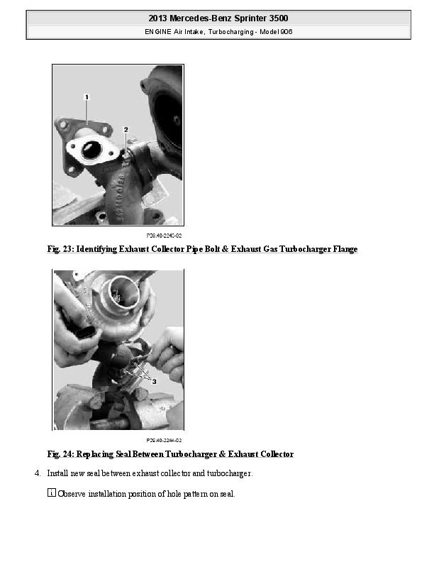
Fig. 24: Replacing Seal Between Turbocharger & Exhaust Collector
4. Install new seal between exhaust collector and turbocharger.
Observe installation position of hole pattern on seal.
5. Screw in bolts (2, 3) finger-tight.
It must be possible to move the exhaust gas turbocharger in the direction of the exhaust collector pipe.
6. Install exhaust gas turbocharger with old seal on oil supply connection fitting
7. Screw exhaust collector pipe alternately on right and left exhaust manifold to old seal hand-tight.
8. Tighten bolts (2) fully.
Displacement between exhaust collector pipe and exhaust gas turbocharger leads to tension which can cause considerable engine damage Observe tightening torque.
9. Loosen bolts between exhaust collector pipe and exhaust manifold again.
10. Remove exhaust gas turbocharger from oil supply connection fittings.
11. Carefully remove turbocharger with exhaust collector.
Displacement between exhaust collector pipe and exhaust gas turbocharger leads to tension which can cause considerable engine damage
12. Clamp exhaust collector pipe with exhaust gas turbocharger on flange (1) into vise and carefully tighten bolt (3).
Displacement between exhaust collector pipe and exhaust gas turbocharger leads to tension which can cause considerable engine damage
Helper required and observe tightening torque.
13. Remove exhaust gas turbocharger with exhaust collector pipe from vise.
Aid of helper required.
BOLT PLAN FOR CHARGE AIR MANIFOLD - AR09.41-D-1310-01S
CHARGE AIR PIPE/CHARGE AIR COOLING
1. Tighten all bolts (1 to 19) finger-tight to charge air manifold (20).
Screw on lifting eye (21) when screwing on bolts (7 and 10).
2. Tighten bolts (1 to 19) according to bolt plan, start with bolt (1).
Observe tightening torque.
3. Tighten bolts (1 and 11) again.
Observe tightening torque.
Fig. 25: Identifying Charge Air Manifold Bolts Tightening Sequence
BOLT PLAN FOR CHARGE AIR MANIFOLD - AR09.41-D-1310-01SG
CHARGE AIR DISTRIBUTION LINE TO CYLINDER HEAD BOLT TORQUE SPECIFICATION - ENGINE 642
...


