Honda Element 2003-2011 Workshop Repair & Service Manual
Catalog:
Model:
Complete digital workshop manual contains service, maintenance, and troubleshooting information for the Honda Element 2003-2011. Diagnostic and repair procedures are covered in great detail to repair, maintain, rebuild, refurbish or restore your vehicle like a professional mechanic in local service/repair workshop. This cost-effective quality manual is 100% complete and intact as should be without any missing pages. It is the same factory shop manual used by dealers that guaranteed to be fully functional to save your precious time.
This manual for Honda Element 2003-2011 is divided into different sections. Each section covers a specific component or system and, in addition to the standard service procedures, includes disassembling, inspecting, and assembling instructions. A table of contents is placed at the beginning of each section. Pages are easily found by category, and each page is expandable for great detail. It is in the cross-platform PDF document format so that it works like a charm on all kinds of devices. You do not need to be skilled with a computer to use the manual.
ACCESSORIES & EQUIPMENT Audio.pdf
ACCESSORIES & EQUIPMENT Bumpers.pdf
ACCESSORIES & EQUIPMENT Consoles.pdf
ACCESSORIES & EQUIPMENT Cruise Control.pdf
ACCESSORIES & EQUIPMENT Dashboard.pdf
ACCESSORIES & EQUIPMENT Doors.pdf
ACCESSORIES & EQUIPMENT Entry Lights Control System.pdf
ACCESSORIES & EQUIPMENT Exterior Lights.pdf
ACCESSORIES & EQUIPMENT Exterior Trim.pdf
ACCESSORIES & EQUIPMENT Fenderwell.pdf
ACCESSORIES & EQUIPMENT Frame.pdf
ACCESSORIES & EQUIPMENT Fuel Fill Door.pdf
ACCESSORIES & EQUIPMENT Gauges.pdf
ACCESSORIES & EQUIPMENT Glass.pdf
ACCESSORIES & EQUIPMENT Hatch.pdf
ACCESSORIES & EQUIPMENT Hood.pdf
ACCESSORIES & EQUIPMENT Horns.pdf
ACCESSORIES & EQUIPMENT Ignition Switch.pdf
ACCESSORIES & EQUIPMENT Immobilizer System.pdf
ACCESSORIES & EQUIPMENT Interior Lights.pdf
ACCESSORIES & EQUIPMENT Interior Trim.pdf
ACCESSORIES & EQUIPMENT Keyless/Power Door Lock System.pdf
ACCESSORIES & EQUIPMENT Mirrors.pdf
ACCESSORIES & EQUIPMENT Multiplex Control System.pdf
ACCESSORIES & EQUIPMENT Navigation System.pdf
ACCESSORIES & EQUIPMENT Openers.pdf
ACCESSORIES & EQUIPMENT Power Mirrors.pdf
ACCESSORIES & EQUIPMENT Power Windows.pdf
ACCESSORIES & EQUIPMENT Rear Window Defogger.pdf
ACCESSORIES & EQUIPMENT Reminder Systems.pdf
ACCESSORIES & EQUIPMENT Safety Indicator System.pdf
ACCESSORIES & EQUIPMENT Seats.pdf
ACCESSORIES & EQUIPMENT Skylight.pdf
ACCESSORIES & EQUIPMENT Tailgate.pdf
ACCESSORIES & EQUIPMENT Turn Signal/Hazard Warning Lights.pdf
ACCESSORIES & EQUIPMENT Wipers/Washers.pdf
BRAKES Conventional Brake Components.pdf
BRAKES VSA (Vehicle Stability Assist) System Components.pdf
DRIVELINE/AXLES Driveline/Axle.pdf
DRIVELINE/AXLES Rear Differential.pdf
ELECTRICAL Charging System.pdf
ELECTRICAL Fuse/Relay Boxes.pdf
ELECTRICAL OEM Fuse/Relay Boxes.pdf
ELECTRICAL OEM Ground-To-Components Index.pdf
ELECTRICAL OEM Wiring Diagram General Information - All Models.pdf
ELECTRICAL Power Distribution.pdf
ELECTRICAL Relay & Control Unit Locations.pdf
ELECTRICAL Relays.pdf
ELECTRICAL Under-Dash Fuse/Relay Box.pdf
ELECTRICAL Under-Hood Fuse/Relay Box.pdf
ENGINE Cooling System.pdf
ENGINE Cylinder Head.pdf
ENGINE Engine Assembly.pdf
ENGINE Engine Block.pdf
ENGINE Engine Lubrication.pdf
ENGINE Fan Controls.pdf
ENGINE Ignition System.pdf
ENGINE Intake Manifold & Exhaust System.pdf
ENGINE PERFORMANCE Advanced Diagnostics.pdf
ENGINE PERFORMANCE Catalytic Converter System.pdf
ENGINE PERFORMANCE Electronic Throttle Control System.pdf
ENGINE PERFORMANCE EVAP System.pdf
ENGINE PERFORMANCE Firing Order & Cylinder Identification.pdf
ENGINE PERFORMANCE Fuel & Emissions Systems.pdf
ENGINE PERFORMANCE Fuel Supply System.pdf
ENGINE PERFORMANCE Idle Control System.pdf
ENGINE PERFORMANCE Intake Air System.pdf
ENGINE PERFORMANCE PCV System.pdf
ENGINE PERFORMANCE PGM-FI System.pdf
ENGINE PERFORMANCE VTEC/VTC.pdf
ENGINE Starting System.pdf
GENERAL INFORMATION Battery Cable Reset.pdf
GENERAL INFORMATION Cabin Air Filter.pdf
GENERAL INFORMATION General Information.pdf
GENERAL INFORMATION Maintenance.pdf
GENERAL INFORMATION Reminder Indicator Reset Procedures.pdf
GENERAL INFORMATION Specifications.pdf
GENERAL INFORMATION Torque Specifications - General.pdf
HVAC.pdf
RESTRAINTS Seat Belts.pdf
RESTRAINTS SRS (Supplemental Restraint System).pdf
STEERING Steering.pdf
SUSPENSION Front & Rear Suspension.pdf
SUSPENSION Front Suspension.pdf
SUSPENSION Rear Suspension.pdf
SUSPENSION TPMS (Tire Pressure Monitoring System).pdf
SYSTEM WIRING DIAGRAMS.pdf
TRANSMISSION Automatic Transmission.pdf
TRANSMISSION Clutch.pdf
TRANSMISSION Manual Transmission.pdf
EXCERPT:
2007-11 SUSPENSION
Rear Suspension - Element
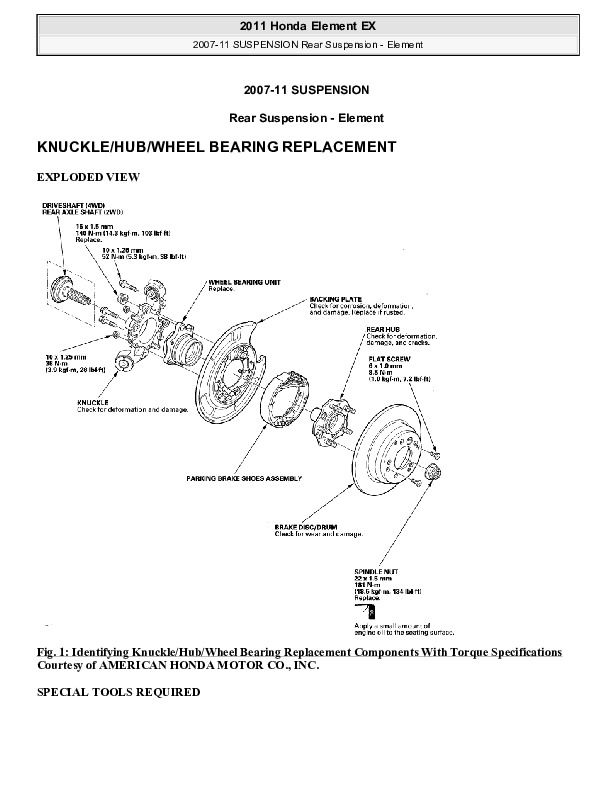
KNUCKLE/HUB/WHEEL BEARING REPLACEMENT
EXPLODED VIEW
Fig. 1: Identifying Knuckle/Hub/Wheel Bearing Replacement Components With Torque Specifications
SPECIAL TOOLS REQUIRED
Attachment, 62 x 68 mm 07746-0010500
Driver 07749-0010000
Hub dis/assembly tool 07965-SA70100
Support base 07965-SD90100
KNUCKLE/HUB REPLACEMENT
1. Raise the rear of the vehicle, and support it with safety stands in the proper locations (see LIFT ANDSUPPORT POINTS ).
2. Remove the wheel nuts and rear wheel.
Fig. 2: Identifying Rear Wheel & Wheel Nuts With Torque Specification
3. Release the parking brake lever.
4. Remove the brake hose mounting bolt (A).
Fig. 3: Identifying Brake Hose Mounting Bolt With Torque Specifications
5. Remove the brake caliper bracket mounting bolts (B), then hang the caliper assembly (C) from the knuckle. To prevent damage to the caliper or brake hose, use a short piece of wire to hang the caliper assembly from the undercarriage. Do not twist the brake hose excessively.
6. Release the parking brake, and remove the brake disc/drum from the rear hub (see REAR BRAKE DISC REPLACEMENT ).
7. Raise the stake (A) of the spindle nut (B), then remove and discard the nut. Remove the rear axle shaft (C) from vehicles with 2WD.
Fig. 4: Identifying Spindle Nut With Torque Specifications
8. Check the rear hub for damage and cracks.
9. Remove the parking brake shoes (see PARKING BRAKE SHOE REPLACEMENT ).
10. Remove the parking brake cable (A) from the backing plate.
NOTE: The parking brake cable must not be bent or distorted. This will lead to stiff operation and premature cable failure.
Fig. 5: Identifying Parking Brake Cable With Torque Specifications
11. Remove the wheel sensor (A) from the knuckle. Do not disconnect the wheel sensor connector.
Fig. 6: Identifying Wheel Sensor With Torque Specifications
12. Place a floor jack under the trailing arm (A) to support it.
NOTE: Do not place the jack against the plate section of the trailing arm. Be careful not to damage any suspension components.
...


