Suzuki Splash 2008-2015 Workshop Repair & Service Manual
Catalog:
Model:
Complete workshop manual contains service, maintenance, and troubleshooting information for the 2008-2015 Suzuki Splash. Diagnostic and repair procedures are covered in great detail to repair, maintain, rebuild, refurbish or restore your vehicle like a professional mechanic in local service/repair workshop. This cost-effective quality manual is 100% complete and intact as should be without any missing pages. It is the same factory shop manual used by dealers that guaranteed to be fully functional to save your precious time.
This manual for 2008-2015 Suzuki Splash is divided into different sections. Each section covers a specific component or system and, in addition to the standard service procedures, includes disassembling, inspecting, and assembling instructions. A table of contents is placed at the beginning of each section. Pages are easily found by category, and each page is expandable for great detail. You do not need to be skilled with a computer to use the manual.
MAKE: Suzuki
MODEL: Splash (A5B Series)
YEAR: 2008 2009 2010 2011 2012 2013 2014 2015
LANGUAGE: EN/DE/ES/FR/GK/HU/IT/NL
OS: Windows (Internet Explorer)
EXCERPT:
Engine Assembly Removal and Installation
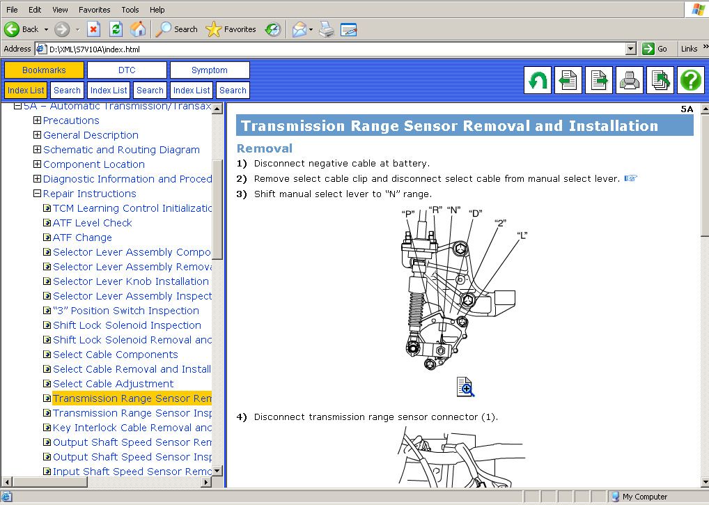
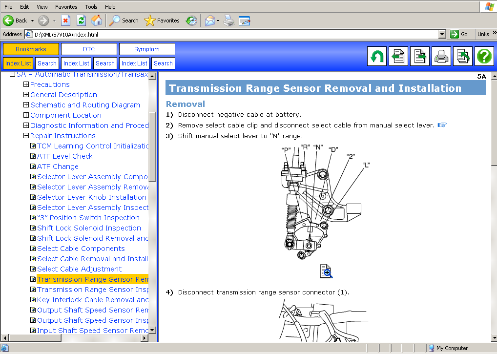
Removal
1)Disconnect negative (–) and positive (+) cable at battery.
2)Remove battery from vehicle.
3)Remove glow plug control module.
4)Remove battery tray from vehicle.
5)Remove engine hood after disconnecting windshield washer hose.
6)Remove engine cover.
7)Remove air cleaner assembly with MAF and IAT sensor.
8)Remove intercooler.
9)Remove ECM.
10)Remove cowl top cover and cowl top panel.
11)Drain engine oil.
12)Drain transaxle oil, if necessary.
13)Drain cooling system.
14)Remove right and left side engine under covers.
15)Remove accessory drive belt.
16)With hose connected, detach A/C compressor from its bracket (if equipped).
CAUTION:
Suspend removed A/C compressor at a place where no damage will be caused during removal and installation of engine assembly.
17)Disconnect the following pipes and hoses:
•Brake booster hose (1)
•Intercooler outlet No.2 hose (2)
•Intercooler outlet pipe (3)
•Fuel feed hose (4)
•Fuel return hose (5)
•Radiator inlet hose (6) and outlet hose
•Degassing tank outlet hose (7)
•Heater inlet and outlet hoses (8)
•Clutch hose and pipe (9)
•Vacuum hose (DPF® model) (10)
18)Disconnect the following electric wires:
•Ground wire from exhaust manifold (11)
•Ground wire from upper member (12)
•Magnet clutch switch of A/C compressor (if equipped)
•Each wire harness clamps (13)
•Injector harness (14)
•Injector harness from ECM (15)
•Engine harness (16)
•Main harness (17)
19)Disconnect the following cables from transaxle:
•Gear select control cable (18)
•Gear shift control cable (19)
20)Remove exhaust No.1 pipe.
21)By using chain hoist (1), support engine assemble with engine hangers (2).
CAUTION:
Be sure to remove / disconnect part(s), which interfere with chain hoist, if necessary.
Failure to follow this CAUTION could result in damage by chain hoist.
22)Remove suspension frame.
23)Remove engine left mounting bracket nuts (1) and engine right mounting bracket nuts (2).
24)Before removing engine with transaxle from engine compartment, recheck to make sure all hoses, pipes, electric wires and cables are disconnected from engine and transaxle.
25)Lower engine with transaxle from engine compartment.
26)Support center bearing support, transaxle case and lower crankcase using pad at hatched parts (1) indicated in figure.
27)Disconnect transaxle from engine.
28)Remove clutch cover and clutch disk.
Installation
1)Install clutch cover and clutch disk.
2)Connect transaxle to engine.
3)Lift engine with transaxle into engine compartment using chain hoist.
4)Install engine left mounting bracket nuts (1) and new engine right mounting bracket nuts (2). Tighten these nuts to specified torque.
Tightening torque
Engine left mounting bracket nut (a): 55 N·m (5.6 kg-m, 40.5 lbf-ft)
Engine left mounting bracket nut (b): 55 N·m (5.6 kg-m, 40.5 lbf-ft)
5)Install suspension frame.
6)Remove chain hoist.
7)Install exhaust No.1 pipes.
8)Reverse disconnected hoses, pipes, cables and electric wires for connection in removal procedure.
9)Install A/C compressor to its bracket (if equipped).
10)Install accessory drive belt.
11)Install right and left side engine under covers.
12)Install intercooler.
13)Install cowl top cover and cowl top panel.
14)Install ECM.
15)Install air cleaner assembly with MAF and IAT sensor.
16)Install engine cover.
Tightening torque
Engine cover bolt: 8.0 N·m (0.82 kg-m, 6.0 lbf-ft)
17)Refill engine with engine oil.
18)Refill transaxle with transaxle oil.
19)Refill cooling system with coolant.
20)Refill clutch fluid and bleed air from system.
21)Install engine hood and connect windshield washer hose.
22)Install battery tray.
23)Install glow plug control module.
24)Connect positive (+) and negative (–) cable at battery.
25)Install battery.
26)Verify that there is no fuel leakage, coolant leakage, oil leakage and exhaust gas leakage at each connection.
Main Bearings Inspection
General information
•Service main bearings are available in standard size and 0.127 mm undersize, and standard size and undersize has 3 kinds of bearings differing in thickness.
•Upper half of bearing (1) has oil groove (2) as shown in figure.
Install this half with oil groove to cylinder block.
•Lower half of bearing does not have oil groove.
Visual inspection
Check bearings for pitting, scratches, wear or damage.
If any malcondition is found, replace both upper and lower halves.
Never replace either half without replacing the other half.
Main bearing clearance
NOTE:
Do not rotate crankshaft while gauging plastic is installed.
1)Before checking bearing clearance, clean bearing and crankshaft journal.
2)Install bearing to cylinder block and main bearing cap.
3)Place a piece of gauging plastic (1) to full width of crankshaft journal as contacted by bearing (parallel to crankshaft), avoiding oil hole.
4)Install lower crankcase.
NOTE:
It is not necessary to replace new crankcase bolts for measuring procedure.
5)Remove cap and using a scale (1) on gauging plastic (2) envelope, measure gauging plastic width at the widest point (clearance).
If clearance is out of specification, replace bearing.
Always replace both upper and lower bearing as a set.
Main bearing clearance:
0.026 – 0.050 mm (0.0012 – 0.0019 in.)
Selection of Main Bearings
Standard bearing
If bearing is in malcondition, or bearing clearance is out of specification, select a new standard bearing according to the following procedure and install it.
1)First check journal diameter. As shown in figure, crank web No.4 has stamped alphabets.
Three kinds of alphabets (“A”, “B” and “C”) represent the following journal diameters.
Stamped alphabets on crank web No.4 represent journal diameters marked with an arrow in figure respectively. For example, stamped alphabet “A” indicates that corresponding journal diameter is 50.994 – 51.0000 mm (2.0077 – 2.0078 in.).
Crankshaft journal diameter
Stamped alphabet Journal diameter
A 50.994 – 51.000 mm
(2.0077 – 2.0078 in.)
B 50.988 – 50.994 mm
(2.0074 – 2.0076 in.)
C 50.982 – 50.998 mm
(2.0072 – 2.0074 in.)


