Case 621B, 721B Loaders Workshop Repair & Service Manual
Catalog:
Model:
Complete official workshop manual contains service, maintenance, and troubleshooting information for the Case 621B, 721B Loaders. Diagnostic and repair procedures are covered in great detail to repair, maintain, rebuild, refurbish or restore your Case 621B, 721B Loaders like a professional mechanic in local service/repair workshop. This cost-effective quality manual is 100% complete and intact as should be without any missing pages. It is the same factory shop manual used by dealers that guaranteed to be fully functional to save your precious time.
This manual for Case 621B, 721B Loaders is divided into different sections. Each section covers a specific component or system and, in addition to the standard service procedures, includes disassembling, inspecting, and assembling instructions. A table of contents is placed at the beginning of each section. Pages are easily found by category, and each page is expandable for great detail. It is in the cross-platform PDF document format so that it works like a charm on all kinds of devices. You do not need to be skilled with a computer to use the manual.
1,860 pages, bookmarked, Searchable, Printable, high quality PDF
621B, 721B Loaders Service Manual.pdf
621 B 6T-590; 721 B 6T-830
MODELS Covered
Case 621B 721B loader
621B 6T-590 Engine
721B 6T-830 Engine
SECTIONS covered
General
Loctite Product Chart
Standard Torque Specifications
Fluids and Lubricants
Engines
Engine Removal and Installation and Radiator Removal and Installation – 621B
Engine Removal and Installation and Radiator Removal and Installation – 721B
Stall Tests
621B 6T-590 Engine
Specification Details
Cylinder Head and Valve Train
Cylinder Block – Crankshaft, Pistons, Rods, Sleeves, Camshaft,
Bearings, Seals, and Flywheel
Lubrication System
Cooling System
Turbocharger
721B 6T-830 Engine
Specification Details
Cylinder Head and Valve Train
Cylinder Block – Crankshaft, Pistons, Rods, Sleeves, Camshaft,
Bearings, Seals, and Flywheel
Lubrication System
Cooling System
Turbocharger
Turbocharger Failure Analysis
Fuel System
621B 6T-590 Engine
Fuel System and Filters
Fuel Injection Pump and Drive Gear
Fuel Injectors
721B 6T-830 Engine
Fuel System and Filters
Fuel Injection Pump and Drive Gear
Fuel Injectors
Description
Electrical
Removal and Installation of Starter and Alternator
Electrical Schematics, Troubleshooting and
Using Booster Batteries to Start the Engine
Electrical Schematics and Troubleshooting – Units with Auto Shift Transmission
Starter and Starter Solenoid – Nippondenso – 621B
Starter and Starter Solenoid – Nippondenso – 721B
Batteries
Instrument Cluster and Gauges
65 Ampere Alternator – Bosch
Steering
Removal and Installation of Steering Components
Steering Specifications and Troubleshooting
Steering Control Valve
Flow Control Valve
Steering Cylinder
Center Pivot
Auxiliary Steering Motor and Pump
Power Train
Removal and Installation of Power Train Components
Transmission Specifications, Schematic, and Troubleshooting – Units Without Auto
Shift Transmission
Transmission Specifications, Schematic, and Troubleshooting – Units With Auto Shift
Transmission
Transmission Repair – 621B (4WG150)
Transmission Repair – 721B (4WG180)
Front and Rear Axle Repair
Drive Shaft, Center Bearing and Universal Joints
Wheels and Tires
Transmission Control Valve – Units Without Auto Shift Transmission
Transmission Control Valve – Units With Auto Shift Transmission
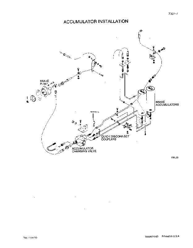
Brakes
Removal and installation of Brake Components
Hydraulic Brake Troubleshooting
Brake Pump
Brake Accumulators
Brake Actuator Valve
Brake Accumulator Valve
Parking Brake
NOTE: For parking brake and brake pedal adjustments, see Section 9009.
Hydraulics
Removal and Installation of Hydraulic Components
Hydraulic Specifications, Schematics. Troubleshooting and Pressure Checks
Cleaning the Hydraulic System
Hydraulic Pump
Loader Control Valve
Cylinders
Coupler Lock Valve • XT Loader
Remote Control Valves
Pressure Reductng’Sequence Valve
Chassis
Air Conditioning Troubleshooting and System Checks
Air Conditioning Troubleshooting and System Checks – For Systems with HFC-134a
Refrigerant
Air Conditioner System Service • Refrigerant Recovery,
System Evacuation and Recharging
Air Conditioner System Service • Refrigerant Recovery, System Evacuation and
Recharging for Systems with HFC-134a Refrigerant
Removal and Installation of Air Conditioning Components
Removal and Installation of Air Conditioning Components – For Systems with
HFC-134a Refrigerant
Air Conditioning Compressor and Clutch
Air Conditioning Compressor and Clutch – For Systems with HFC-134a Refrigerant
Loader
ROPS Cab and ROPS Canopy
Seat and Seat Belts
Suspension Seat
Pedals and Levers
Cab Window Replacement
EXCERPT:
STEP 80
Measure the cylinder sleeve bore for taper as follows:
1. Measure the bore parallel to the crankshaft at the top end of the ring travel zone.
2. Measure the bore in the same position at the bottom end of the ring travel zone.
3. Measure the bore at right angles to the crankshaft at the top end of the ring travel zone.
4. Measure the bore in the same position at the bottom end of the travel zone.
Compare the results of the measurements (1) and (3) with (2) and (4), to find out if the bore has taper. To measure use a inside micrometer, bore gauge or taper gauge. If the taper is more than 0.04 mm, the cylinder sleeve must be replaced.
STEP 81
Measure the cylinder sleeve bores for out-of-round as follows:
1. Measure the bore parallel to the crankshaft at the top end of the ring travel.
2. Measure the bore in the same position at the bottom end of the ring travel.
3. Measure the bore at right angles to the crankshaft at the top end of the ring travel.
4. Measure the bore in the same position at the bottom end of the ring travel.
Compare the measurements (1) and (3) to find the outof-round wear at the top end of the bore.
Compare the measurements (2) and (4) to find the outof-round wear at the bottom of the bore.
If out-of-round is more than 0.04 mm, the cylinder sleeve must be replaced.
Removing the Cylinder Sleeves
IMPORTANT: Cover the crankshaft journals with a clean cloth. Foreign material from the cylinder sleeve or the cylinder block will cause damage to the crankshaft.
STEP 82
Install a sleeve puller to remove the cylinder sleeve. Position the puller in the sleeve. Make sure that the jaws of the puller do not contact the four block lugs. Tighten the lock bar against the cylinder sleeve.
IMPORTANT: Make sure that the jaws of the sleeve puller do not contact the block lugs.
STEP 83
Carefully turn the bearing nut until the cylinder sleeve is loose from the cylinder block.
STEP 84
Remove the cylinder sleeve from the cylinder block.
Remove the a-ring from the cylinder sleeve.
...
Case 621B, 721B Loaders Workshop Repair & Service Manual


