Caterpillar 931/941/941B/951/951B/951C Loaders Workshop Repair & Service Manual
Catalog:
Model:
Caterpillar 931/941/941B/951/951B/951C Loaders Workshop Repair & Service Manual
Complete official service manual contains service, maintenance, and troubleshooting information for the Caterpillar 931, 941, 941B, 951, 951B, 951C Track-Type Loader. Diagnostic and repair procedures are covered in great detail to repair, maintain, rebuild, refurbish or restore your Caterpillar 941, 941B, 951B, 951C Track-Type Loader like a professional mechanic in local service/repair workshop. This cost-effective quality manual is 100% complete and intact as should be without any missing pages. It is the same factory shop manual used by dealers that guaranteed to be fully functional to save your precious time.
This manual for Caterpillar 931, 941, 941B, 951, 951B, 951C Traxcavator is divided into different sections. Each section covers a specific component or system and, in addition to the standard service procedures, includes disassembling, inspecting, and assembling instructions. A table of contents is placed at the beginning of each section. Pages are easily found by category, and each page is expandable for great detail. It is in the cross-platform PDF document format so that it works like a charm on all kinds of devices. You do not need to be skilled with a computer to use the manual.
2,312 pages, bookmarked, Searchable, Printable, high quality PDF
FILELIST:
UEG0689S - Parts Book (951C Traxcavator SN86J2598-86J4041).pdf
UEG0689S - Parts Book (951C Traxcavator SN86J2598-up).pdf
REG00957 - Service Manual - Disassembly & Assembly (941-951B Power Train).pdf
REG00803 - System Operation, Testing & Adjusting (951 Track-Type Loader Power Train).pdf
GEG00582 - Lubrication & Maintenance Guide (951 Traxcavator).pdf
GEG00986 - Lubrication & Maintenance Guide (951 Traxcavator).pdf
REG00776 - System Operation, Testing & Adjusting (941B & 951C Track-Type Loader Hydraulic System).pdf
REG01400 - Service Manual - Disassembly & Assembly (Four & Six Cylinder 4.75" Bore Engines Sleeve Metering Fuel System).pdf
REG00684 - Disassembly & Assembly (General Instructions).pdf
Service Manual - Disassembly & Assembly - 941-951 Engine.pdf
SENR2076 - Specifications (951 Track-Type Loader Power Train).pdf
SENR2003 - Specifications (941 B & 951C Track-Type Loader Hydraulic System).pdf
REG00958 - Service Manual - Disassembly & Assembly (941-951 Loader Components).pdf
REG00878 - Service Manual - Flow Meter TEE Test Procedure - I.pdf
Service Manual - Disassembly & Assembly - 941-951 Tool Charts.pdf
REG00998 - Service Manual - Flow Meter Tee Test Procedure.pdf
REG01325 - Systems Operation (931 Track-Type Loader Power Train).pdf
REG00910 - Service Manual - Flow Meter TEE Test - Tools.pdf
REG00541 - Systems Operation (941 Track-Type Loader Power Train).pdf
REG01328 - Testing & Adjusting (931 Track-Type Loader Hydraulic System).pdf
REG01328 - Systems Operation (931 Track-Type Loader Hydraulic System).pdf
REG01333 - Testing & Adjusting (Power Shift Transmission (D5)).pdf
REG00955 - General Service Information (941 & 951 Engine Tool Selection Chart).pdf
REG01324 - Testing & Adjusting (Power Shift Transmission).pdf
REG01332 - Testing & Adjusting (941_951 Power Shift Transmission).pdf
REG00540 - Control Valve & Tank (163 Hydraulic Control).pdf
REG00540 - Systems Operation (163 Hydraulic Control).pdf
REG00540 - Testing & Adjusting (163 Hydraulic Control).pdf
SENR3581 - Specifications (37-MT, 41-MT, & 42-MT Series Starting Motors).pdf
REG01325 - Testing & Adjusting (931 Track-Type Loader Power Train).pdf
RENR1252 - Specifications (26SI Series Alternator).pdf
SENR4130 - Specifications (HDB Series & M1 Series Heavy Duty Brushless Alternators).pdf
SENR7951 - Schematic (941B & 951C Track-Type Loader Hydraulic System).pdf
REG00541 - Testing & Adjusting (941 Track-Type Loader Power Train).pdf
SENR2082 - Specifications (N3 Series Brushless Alternators).pdf
REG01326 - Testing & Adjusting (931 Power Shift Transmission).pdf
941B & 951C Track-Type Loader Hydraulic System Schematic.pdf
941B & 951C Track-Type Loader Hydraulic System Schematic.djvu
REG00540 - Specifications (163 Hydraulic Control)
REG00956 - Disassembly & Assembly (941 & 951 Engine)
REG01327 - Specifications (931 Track-Type Loader Power Train)
RENR1252 - Disassembly & Assembly (26SI Series Alternator)
RENR1252 - Systems Operation (26SI Series Alternator)
RENR1252 - Testing & Adjusting (26SI Series Alternator)
SENR2003 - Specifications (941B & 951C Track-Type Loader Hydraulic System)
SENR2082 - Systems Operation (N3 Series Brushless Alternators)
SENR2082 - Testing & Adjusting (N3 Series Brushless Alternators)
SENR2082 - Troubleshooting (N3 Series Brushless Alternators)
SENR3334 - Disassembly & Assembly (Air Conditioning & Heating R-12 All Caterpillar Machines)
SENR3334 - Specifications (Air Conditioning & Heating R-12 All Caterpillar Machines)
SENR3334 - Systems Operation (Air Conditioning & Heating R-12 All Caterpillar Machines)
SENR3334 - Testing & Adjusting (Air Conditioning & Heating R-12 All Caterpillar Machines)
SENR3581 - Disassembly & Assembly (37-MT, 41-MT, & 42-MT Series Starting Motors)
SENR3581 - Systems Operation (37-MT, 41-MT, & 42-MT Series Starting Motors)
SENR3581 - Testing & Adjusting (37-MT, 41-MT, & 42-MT Series Starting Motors)
SENR3581 - Troubleshooting (37-MT, 41-MT, & 42-MT Series Starting Motors)
SENR4130 - Disassembly & Assembly (HDB Series & M1 Series Heavy Duty Brushless Alternators)
SENR4130 - Systems Operation (HDB Series & M1 Series Heavy Duty Brushless Alternators)
SENR4130 - Testing & Adjusting (HDB Series & M1 Series Heavy Duty Brushless Alternators)
SENR4130 - Troubleshooting (HDB Series & M1 Series Heavy Duty Brushless Alternators)
SENR7001 - Specifications (941 Track-Type Loader Power Train)
941B & 951C Track-Type Loader Hydraulic System Schematic.djvu
941B & 951C Track-Type Loader Hydraulic System Schematic.pdf
GEG00582 - Lubrication & Maintenance Guide (951 Traxcavator).pdf
GEG00986 - Lubrication & Maintenance Guide (951 Traxcavator).pdf
REG00540 - Control Valve & Tank (163 Hydraulic Control).pdf
REG00540 - Specifications (163 Hydraulic Control)
Blade Lift Cylinder (5J8173).pdf
Blade Tilt Cylinder (2J1402).pdf
Control Valve (5J9869).pdf
Control Valve (6J3117).pdf
External Valve (4J487).pdf
Hydraulic Oil Pump (6J7400 & 7J607).pdf
Oil Filter.pdf
Pressure Relief Valves (4J801 & 4J1129).pdf
Ripper Cylinder (2K3663.pdf
REG00540 - Systems Operation (163 Hydraulic Control).pdf
REG00540 - Testing & Adjusting (163 Hydraulic Control).pdf
REG00541 - Systems Operation (941 Track-Type Loader Power Train).pdf
REG00541 - Testing & Adjusting (941 Track-Type Loader Power Train).pdf
REG00684 - Disassembly & Assembly (General Instructions).pdf
REG00776 - System Operation, Testing & Adjusting (941B & 951C Track-Type Loader Hydraulic System).pdf
REG00803 - System Operation, Testing & Adjusting (951 Track-Type Loader Power Train).pdf
REG00878 - Service Manual - Flow Meter TEE Test Procedure - I.pdf
REG00910 - Service Manual - Flow Meter TEE Test - Tools.pdf
REG00955 - General Service Information (941 & 951 Engine Tool Selection Chart).pdf
REG00956 - Disassembly & Assembly (941 & 951 Engine)
Air Induction And Exhaust System.pdf
Basic Block Components.pdf
Cooling System Components.pdf
Crankshaft Front Oil Seal.pdf
Engine Removal And Installation.pdf
Flywheel And Flywheel Housing.pdf
Fuel System Components.pdf
Important Information.pdf
Lubrication System Components.pdf
Timing Gear Cover.pdf
Timing Gears.pdf
REG00957 - Service Manual - Disassembly & Assembly (941-951B Power Train).pdf
REG00958 - Service Manual - Disassembly & Assembly (941-951 Loader Components).pdf
REG00998 - Service Manual - Flow Meter Tee Test Procedure.pdf
REG01324 - Testing & Adjusting (Power Shift Transmission).pdf
REG01325 - Systems Operation (931 Track-Type Loader Power Train).pdf
REG01325 - Testing & Adjusting (931 Track-Type Loader Power Train).pdf
REG01326 - Testing & Adjusting (931 Power Shift Transmission).pdf
REG01327 - Specifications (931 Track-Type Loader Power Train)
Bevel Gear And Pinion Shaft Free Movement (Backlash).pdf
Bevel Gear And Pinion.pdf
Brake Adjustment.pdf
Control Linkage For Transmission.pdf
Final Drive.pdf
Front Idler And Recoil Spring.pdf
Hydraulic Controls (1P571).pdf
Introduction.pdf
Lubrication Relief Valve (9S6979).pdf
Oil Pump For The Transmission (1P4165).pdf
Plugs For Steering Clutch Case.pdf
Pressures For The Hydraulic Controls.pdf
Rollover Protective Structure (Rops).pdf
Steering Clutch Adjustment.pdf
Steering Clutch.pdf
Track Adjusting Mechanism.pdf
Track Rollers.pdf
Track.pdf
Transfer Gears.pdf
Transmission (2P2945).pdf
Undercarriage Support.pdf
Universal Joint.pdf
REG01328 - Systems Operation (931 Track-Type Loader Hydraulic System).pdf
REG01328 - Testing & Adjusting (931 Track-Type Loader Hydraulic System).pdf
REG01332 - Testing & Adjusting (941_951 Power Shift Transmission).pdf
REG01333 - Testing & Adjusting (Power Shift Transmission (D5)).pdf
REG01400 - Service Manual - Disassembly & Assembly (Four & Six Cylinder 4.75" Bore Engines Sleeve Metering Fuel System).pdf
RENR1252 - Disassembly & Assembly (26SI Series Alternator)
Alternator - Assemble.pdf
Alternator - Disassemble.pdf
RENR1252 - Specifications (26SI Series Alternator).pdf
RENR1252 - Systems Operation (26SI Series Alternator)
Component Description.pdf
General Information.pdf
Normal Operation.pdf
RENR1252 - Testing & Adjusting (26SI Series Alternator)
Component - Test.pdf
General Information.pdf
Initial Troubleshooting Procedure.pdf
T1 Alternator Output - Test.pdf
T2 Electrical System Current - Test.pdf
T3 Charging System - Test.pdf
T4 Alternator Drive System - Check.pdf
T5 Alternator Current - Test.pdf
T6 Residual Magnetism Restoration.pdf
T7 Identifying Source of Current Draw - Test.pdf
T8 Alternator Overcharging - Test.pdf
SENR2003 - Specifications (941 B & 951C Track-Type Loader Hydraulic System).pdf
SENR2003 - Specifications (941B & 951C Track-Type Loader Hydraulic System)
Auxiliary Control Valve (5J9115).pdf
Cylinders.pdf
Hydraulic Pump (7J583).pdf
Hydraulic Pump (7J584).pdf
Hydraulic Pump (8J8367 & 9J5080).pdf
Introduction.pdf
Loader Frame.pdf
Main Control Valve (5J9114).pdf
Master Valve For The Bucket Positioner (8J82).pdf
Master Valve For The Bucket Positioner (Early Machines) (5J6701).pdf
Relief Valve (Head End Of Tilt Cylinder) (5J9107).pdf
Relief Valve (Rod End Of Tilt Cylinder) (5J9106).pdf
Relief Valve For Main Pressure (3G2350).pdf
Relief Valve For Main Pressure (5J9113).pdf
SENR2076 - Specifications (951 Track-Type Loader Power Train).pdf
SENR2082 - Specifications (N3 Series Brushless Alternators).pdf
SENR2082 - Systems Operation (N3 Series Brushless Alternators)
Component Description.pdf
General Information.pdf
Normal Operation.pdf
SENR2082 - Testing & Adjusting (N3 Series Brushless Alternators)
Alternator - Assemble.pdf
Alternator - Disassemble.pdf
Capacitor - Test.pdf
Field Winding - Test.pdf
Rectifier - Test.pdf
Regulator - Test.pdf
Residual Magnetism - Restore.pdf
Stator - Test.pdf
SENR2082 - Troubleshooting (N3 Series Brushless Alternators)
Charging System.pdf
General Information.pdf
Service Tools.pdf
SENR3334 - Disassembly & Assembly (Air Conditioning & Heating R-12 All Caterpillar Machines)
General Information.pdf
In-Line Refrigerant Dryer - Remove and Install.pdf
Machine Preparation for Disassembly and Assembly.pdf
Receiver-Dryer - Remove and Install.pdf
Refrigerant Accumulator - Remove and Install.pdf
Refrigerant Compressor - Remove and Install.pdf
Refrigerant Expansion Valve - Remove and Install.pdf
Refrigerant Orifice Tube - Remove and Install.pdf
SENR3334 - Specifications (Air Conditioning & Heating R-12 All Caterpillar Machines)
Refrigerant Compressor 1.pdf
Refrigerant Compressor 2.pdf
Refrigerant Compressor.pdf
System Capacities for Refrigerant.pdf
SENR3334 - Systems Operation (Air Conditioning & Heating R-12 All Caterpillar Machines)
Cab Air Filters.pdf
Evaporator Coil.pdf
General Information.pdf
Glossary of Terms.pdf
Heating System Schematic.pdf
Heating and Air Conditioning Control System.pdf
Identifying the Air Conditioning System.pdf
Preparation of Air Conditioner Units for Seasonal Use.pdf
Receiver-Dryer.pdf
Refrigerant Accumulator.pdf
Refrigerant Compressor.pdf
Refrigerant Condenser.pdf
Refrigerant Expansion Valve System.pdf
Refrigerant Expansion Valve.pdf
Refrigerant Orifice Tube System.pdf
SENR3334 - Testing & Adjusting (Air Conditioning & Heating R-12 All Caterpillar Machines)
Air Conditioning System Troubleshooting.pdf
General Troubleshooting Information.pdf
Machine Preparation for Troubleshooting.pdf
Manifold Gauge Set (Refrigerant) - Install.pdf
Manifold Gauge Set (Refrigerant) - Remove.pdf
Refrigerant Compressor Oil - Check.pdf
Refrigerant Leakage - Test.pdf
Refrigerant Recovery.pdf
Refrigerant System - Charge.pdf
Refrigerant System - Evacuate.pdf
Required Tools.pdf
Troubleshooting Heating and Air Conditioning Control System.pdf
Visual Inspection.pdf
SENR3581 - Disassembly & Assembly (37-MT, 41-MT, & 42-MT Series Starting Motors)
General Information.pdf
Starting Motor - Assemble - 37-MT and 41-MT.pdf
Starting Motor - Assemble - 42-MT.pdf
Starting Motor - Disassemble - 37-MT and 41-MT.pdf
Starting Motor - Disassemble - 42-MT.pdf
SENR3581 - Specifications (37-MT, 41-MT, & 42-MT Series Starting Motors).pdf
SENR3581 - Systems Operation (37-MT, 41-MT, & 42-MT Series Starting Motors)
Component Description.pdf
General Information.pdf
Normal Operation.pdf
SENR3581 - Testing & Adjusting (37-MT, 41-MT, & 42-MT Series Starting Motors)
Brush and Brush Holder - Check.pdf
No Load - Test.pdf
Pinion Clearance - Adjust.pdf
Starting Motor Solenoid - Test.pdf
SENR3581 - Troubleshooting (37-MT, 41-MT, & 42-MT Series Starting Motors)
Engine Does Not Crank with Starting Motor On and Pinion Engaging Ring Gear.pdf
General Information.pdf
Service Tools.pdf
Starting Motor Does Not Turn or Turns Slowly.pdf
SENR4130 - Disassembly & Assembly (HDB Series & M1 Series Heavy Duty Brushless Alternators)
Alternator - Disassemble - HDB Series Alternator.pdf
Alternator - Disassemble - M1 Series Alternator (35 Amp).pdf
SENR4130 - Specifications (HDB Series & M1 Series Heavy Duty Brushless Alternators).pdf
SENR4130 - Systems Operation (HDB Series & M1 Series Heavy Duty Brushless Alternators)
Component Description.pdf
General Information.pdf
Normal Operation.pdf
SENR4130 - Testing & Adjusting (HDB Series & M1 Series Heavy Duty Brushless Alternators)
Capacitor - Test.pdf
Field Winding - Test.pdf
Rectifier - Test.pdf
Regulator - Test.pdf
Residual Magnetism - Restore.pdf
Stator - Test.pdf
SENR4130 - Troubleshooting (HDB Series & M1 Series Heavy Duty Brushless Alternators)
Charging System.pdf
General Information.pdf
Service Tools.pdf
SENR7001 - Specifications (941 Track-Type Loader Power Train)
Alignment Of Track Roller Frame.pdf
Bevel Gear And Steering Clutch (Lever Steer).pdf
Bevel Gear And Steering Clutch (Pedal Steer).pdf
Bevel Pinion.pdf
Case And Cover For Steering Clutch.pdf
Checking And Adjusting Alignment Of The Flexible Coupling Drive.pdf
Controls For The Steering Clutch (Lever Steer).pdf
Filter For Steering Clutch (Pedal Steer).pdf
Final Drive.pdf
Flexible Coupling Drive (Earlier 5S3740.pdf
Flexible Coupling Drive (Later 5S3740).pdf
Front Idler And Recoil Spring.pdf
Hydraulic Control For Steering Clutch (Pedal Steer).pdf
Hydraulic Controls For The Transmission.pdf
Introduction.pdf
Oil Pump For The Steering Clutch (Pedal Steer) (5S7863).pdf
Rollover Protective Structure (ROPS).pdf
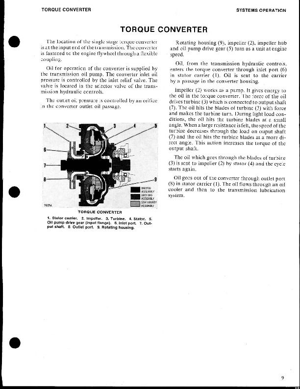
Torque Converter (1T760).pdf
Track Carrier Roller.pdf
Track Roller Frame.pdf
Track Rollers.pdf
Track.pdf
Transmission Filter (4S8679).pdf
Transmission Pump (4S8660).pdf
Transmission.pdf
SENR7951 - Schematic (941B & 951C Track-Type Loader Hydraulic System).pdf
Service Manual - Disassembly & Assembly - 941-951 Engine.pdf
Service Manual - Disassembly & Assembly - 941-951 Tool Charts.pdf
UEG0689S - Parts Book (951C Traxcavator SN86J2598-86J4041).pdf
UEG0689S - Parts Book (951C Traxcavator SN86J2598-up).pdf
...
EXCERPT:
Torque Converter, Transmission And Bevel Pinion
Refer to SERVICE GUIDE for Preliminary Information.
Bottom Removal (Preferred Method)
1. Place machine on 12 in. (304,8 mm) blocks.
2. Position skid plate, 3 ft. x 4 ft. (0,91 x 1,22 m) under transmission.
3-3/4" NC forged eyebolts (three). Attach chains. Forward chain should be adjustable to assure maneuverability of the transmission in this comparatively tight space. 4-Fuel line. Take care not to damage this line during transmission removal and installation.
View from beneath machine.
5-Flywheel housing bolts (four). These are removed to provide clearance.
6-Transmission support bracket. 7-Bolts and washers (ten each).
8. Move transmission forward to clear bevel pinion. Lengthen forward chain slightly, and lower transmission to the floor.
Transmission removal.
Top Removal (Alternate Method)
1. Drain the oil filter.
2. Remove oil filter cover assembly to obtain additional clearance.
3. Follow Steps 3, 4, 5, 6 and 7 as outlined in topic BOTTOM REMOVAL.
4. Move transmission forward to clear bevel pinion.
5. Raise bevel pinion end and lower torque converter end.
6. Insert four 1/2" NC forged eyebolts in bevel pinion housing, and attach chains.
7. Manuever the transmission until it is in position shown and lift transmission from machine.
Torque Converter Removal And Installation
Refer to SERVICE GUIDE for Preliminary Information.
The single stage torque converter is mounted in the torque converter housing on the front of the transmission case.
1. Position transmission on blocks with transfer gears down. Work on a clean surface to avoid introducing dirt into the torque converter or the fluid system. Protect all internal parts of the torque converter during servicing to prevent bumping, burring, scratching, or damaging.
2-Line from transmission sump. 3-Bolts (fifteen). Use two 3/8"-16 forcing screws to separate torque converter case from transmission housing. 4-1/2" NC forged eyebolts (two). Attach chains and remove torque converter and cover assembly. Position output side down on suitable blocks. 5-Bolts (four). 6-Bolts (fifteen). Use two as forcing screws to separate cover assembly from torque converter case. 7-Cover assembly and lubrication units. Lift from torque converter case. 8-Torque converter case. Invert case and torque converter. Remove the eight case-to-carrier bolts. At installation, tighten the bolts to 34-38 lb. ft. (4,12-4,68 m.kg). 9-Torque converter.
10. There are two cored passages in the output end of the torque converter case. At installation, these passages must align with their counterparts in the torque converter carrier assembly.
Torque Converter Disassembly And Assembly
4 At installation, passages in carrier (4) must align with passages in torque converter case.
5, 6, 14 Use four of the bolts (5) as forcing screws to separate impeller (6) from housing (14).
7 When separating stator (7) from impeller, use small wooden blocks under pry bar to prevent damage to impeller.
8, 9, 10, 11, 12, 13 Use an arbor press and 6 in. (152,44 mm) or larger blocks to press drive shaft (8) from carrier (10), bearing (12), races (11 and 13), and turbine (9).
...


