Caterpillar Lift Trucks 2012 Workshop Repair & Service Manual
Catalog:
Model:
Complete digital official shop manual contains service, maintenance, and troubleshooting information for the Caterpillar Lift Trucks. Diagnostic and repair procedures are covered in great detail to repair, maintain, rebuild, refurbish or restore your vehicle like a professional mechanic in local service/repair workshop. This cost-effective quality manual is 100% complete and intact as should be without any missing pages. It is the same factory shop manual used by dealers that guaranteed to be fully functional to save your precious time.
This manual for Caterpillar Lift Trucks is divided into different sections. Each section covers a specific component or system and, in addition to the standard service procedures, includes disassembling, inspecting, and assembling instructions. A table of contents is placed at the beginning of each section. Pages are easily found by category, and each page is expandable for great detail. It is in the cross-platform PDF document format so that it works like a charm on all kinds of devices. You do not need to be skilled with a computer to use the manual.
MAKE: Caterpillar Lift Trucks
Publication Type: HPK, OMM, PSB, Service Manual, Parts Sample
Document Format: PDF [inside Virtual Machine (8.2G)]
MODEL: MCFE (v1.5.0.150; 2011/12/17)
Cushion Tire; Electric Model; Hand Pallet; Large Pneumatic (6 ton - 16 ton); Small Pneumatic (1 ton - 5.5 ton)
Model Numbers:
2EC15 36/48V; 2EC18 36/48V; 2EC20 36/48V; 2EC20 72/80V; 2EC25 36/48V; 2EC25 72/80V; 2EC25E 36/48V; 2EC25E 72/80V; 2EC30 36/48V; 2EC30 72/80V; DP100; DP100N; DP115; DP120N; DP135; DP135N; DP15 FC; DP15 MC; DP150; DP150N; DP15K FC; DP15K MC; DP15N; DP160N; DP18 FC; DP18 MC; DP18K FC; DP18K MC; DP18N; DP20 FC; DP120 MC; DP20CN; DP20K FC; DP20K MC; DP20N; DP25 FC; DP25 MC; DP25K FC; DP25K MC; DP25N; DP30 FC; DP30 MC; DP30K FC; DP30K MC; DP30N; DP35 FC; DP35 MC; DP35K FC; DP35K MC; DP35N; DP40; DP40K; DP40KL; DP40N; DP45; DP45K; DP45N; DP50; DP50CN; DP50K; DP50N; DP55N; DP60; DP70; DP80; DP80N; DP90; DP90N; DPL40; EC15; EC15K; EC15N; EC18K; EC18N; EC20K; EC20N; EC25EN; EC25K; EC25KE; EC25KL; EC25LN; EC25N; EC30K; EC30N; EC35N; EC40N; EC45N; EC55N; EP10KRT; EP10KRT PAC; EP12KRT; EP12KRT PAC; EP13T 24V; EP13T 36V; EP13T 48V; EP15KRT; EP15KRT PAC; EP15T 24V; EP15T 36V; EP15T 48V; EP16 36/48V MCII; EP16 36/48V MCIII; EP16 72/80V MCII; EP16 72/80V MCIII; EP16K; EP16KT; EP16N; EP16NT; EP18 36/48V MCII; EP18 36/48V MCIII; EP18 72/80V MCII; EP18 72/80V MCIII; EP18K; EP18KT; EP18N; EP18NT; EP18T 36V; EP18T 48V; EP20 36/48V MCII; EP20 36/48V MCIII; EP20 72/80V MCII; EP20 72/80V MCIII; EP20CN; EP20K; EP20K PAC; EP20KC; EP20KT; EP20NT; EP20T 36V; EP20T 48V; EP25 36/48V MCII; EP25 36/48V MCIII; EP25 72/80V MCII; EP25 72/80V MCIII; EP25K; EP25K PAC; EP30 36/48V MCII; EP30 36/48V MCIII; EP30 72/80V MCII; EP30 72/80V MCIII; EP30K; EP30K PAC; EP35K; EP35K PAC; EP40; EP45; EP50; F25; F30; F35; F40D; F40D P; F40D SA; F50D; F50D P; F50D SA; F60D; F60D P; F60D SA; FC40; GC15; GC15K-GAS; GC15K-LP; GC18; GC18K-GAS; GC18K-LP; GC20; GC20HP; GC20K HP; GC20K-GAS; GC20K-LP; GC20N; GC25; GC25HP; GC25K HP; GC25K-GAS; GC25K-LP; GC25N; GC28N; GC30; GC30K-GAS; GC30K-LP; GC30N; GC35K; GC40K; GC40K STR; GC40K SWB; GC45K; GC45K STR; GC45K SWB; GC55K; GC55K STR; GC60K; GC70K; GC70K STR; GP15 FC; GP15 MC; GP15K FC; GP15K MC; GP15N; GP15ZN; GP18 FC; GP18 MC; GP18K FC; GP18K MC; GP18N; GP18ZN; GP20 FC; GP20 MC; GP20CN; GP20HN; GP20K FC; GP20K MC; GP20N; GP20ZN; GP25 FC; GP25 MC; GP25HN; GP25K FC; GP25K MC; GP25N; GP25ZN; GP30 FC; GP30 MC; GP30K FC; GP30K MC; GP30N; GP35 FC; GP35 MC; GP35K FC; GP35K MC; GP35N; GP40; GP40K; GP40KL; GP40N; GP45K; GP45N; GP50CN; GP50K; GP50N; GP55N; GPE15N; GPE15ZN; GPE18N; GPE18ZN; GPE20CN; GPE20N; GPE20ZN; GPE25N; GPE25ZN; GPE30N; GPE35N; GPL40; GS-CAT; GT-CAT; M100B; M100D; M100D 36/48V; M100D 72/80V; M120D; M120D 36/48V; M120D 72/80V; M25D; M30D; M35D; M40D; M40D P; M40D SA; M50D; M50D P; M50D SA; M60B; M70B; M70D; M80B; M80D; MC40D; MC60D P; MC60D SA; T100D; T25D; T30D; T40D; T40E; T50D; T50E; T60D; T60E; T70D; T80D; T90D; TC100D; TC400D; TC60D; V100F; V110C; V135C; V155C; V165VC; V180C; V200C; V200C STR; V225C; V25D; V265C; V300C; V30D; V40D; V40D SA; V40E; V50D; V50D SA; V50E; V60E; V70E; V70F; V80E; V80F; V90E; V90F; VC110F; VC40D; VC60D; VC60D SA; VC60E
EXCERPT:
GROUP 11 ENGINE
SPECIFICATIONS.................................... 11-2
STRUCTURE AND OPERATION...................................... 11-3
1. Cylinder Head and Crankcase.............................. 11-3
2. Valve Mechanism.................................................. 11-4
3. Connecting Rods.................................................. 11-4
4. Pistons .......................................... 11-5
5. Timing Gears ................................ 11-5
6. Flywheel........................................ 11-5
TROUBLESHOOTING ............................. 11-6
ON-VEHICLE INSPECTION AND ADJUSTMENT............ 11-8
1. Measuring Compression Pressure....................... 11-8
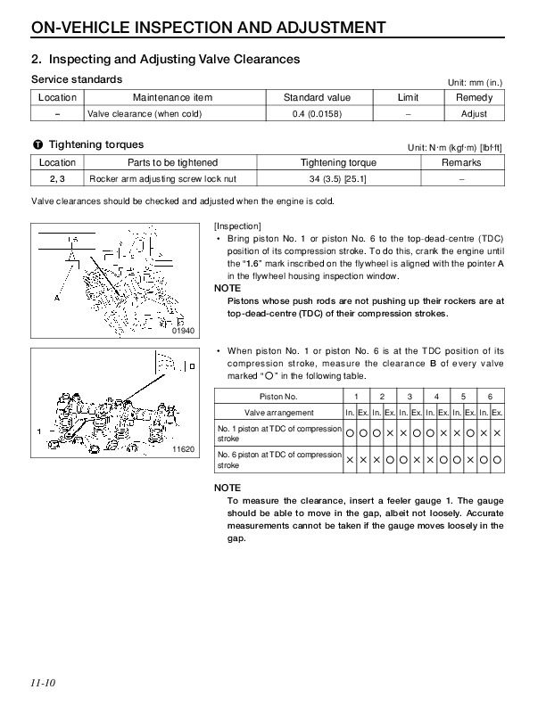
2. Inspecting and Adjusing Valve Clearances.................................. 11-10
CYLINDER HEAD AND VALVE MECHANISM.................. 11-12
PISTONS, CONNECTING RODS, AND CYLINDER LINERS ................... 11-30
FLYWHEEL.............................................. 11-46
TIMING GEARS....................................... 11-52
CAMSHAFT............................................. 11-58
CRANKSHAFT AND CRANKCASE.................................. 11-66
STRUCTURE AND OPERATION
(1). Cylinder Head and Crankcase
1 Connecting plate
2 Glow plug
3 Cylinder liner
4 Crankcase
5 Water jacket
6 Piston
7 Injection nozzle
8 Cylinder head
A: Cylinder liner size mark
Outer diameter mark: 1, 2, 3
Inner diameter mark: A, B
• The cylinder liners 3 are a dry type liners that are easier to remove than wet liners.
Liners are press-fitted into the crankcase 4.
• The cylinder liners 3, crankcase 4, and pistons 6 have size marks. They should be combined as specified according to the size marks.
2. Valve Mechanism
1 Exhaust valve
2 Inlet valve
3 Camshaft
4 Tappet
5 Push rod
6 Rocker shaft
7 Rocker shaft spring
8 Rocker
9 Rocker shaft bracket
10 Valve cap
11 Valve cotter
12 Upper retainer
13 Outer valve spring
14 Inner valve spring
15 Valve stem seal
16 Valve guide
• The valve stem seals 15 are fitted onto the valves 1, 2 to control the amount of lubricant flowing onto the sliding surfaces of the valves 1, 2 and valve guides 16.
• The valve springs 13, 14 are unevenly pitched to prevent abnormal vibration at high speeds. To prevent the inner and outer springs from meshing with each other, the springs are wound in opposite directions.
• To facilitate removal and reinstallation of the camshaft from the rear end of the crankcase, the diameter of each bushing is smaller toward the front of the engine.
3. Connecting Rods
1 Connecting rod bushing
2 Connecting rod
3 Connecting rod bearing
4 Connecting rod cap
5 Connecting rod bolt
A: Alignment mark
B: Weight mark stamp
(A, B, C, D, E, F, G, H, I, V, W, X, Y, Z: <6D16>)
(A, B, C, D, E, F: <6D16-TLE>)
...


