Kobelco SK220, SK220-V, SK220LC, SK220LC-V Workshop Repair & Service Manual
Catalog:
Model:
Complete digital official shop manual contains service, maintenance, and troubleshooting information for the Kobelco SK220, SK220-V, SK220LC, SK220LC-V Crawler Excavators. Diagnostic and repair procedures are covered in great detail to repair, maintain, rebuild, refurbish or restore your excavators like a professional mechanic in local service/repair workshop. This cost-effective quality manual is 100% complete and intact as should be without any missing pages. It is the same factory shop manual used by dealers that guaranteed to be fully functional to save your precious time.
This manual for Kobelco SK220, SK220-V, SK220LC, SK220LC-V Crawler Excavators is divided into different sections. Each section covers a specific component or system and, in addition to the standard service procedures, includes disassembling, inspecting, and assembling instructions. A table of contents is placed at the beginning of each section. Pages are easily found by category, and each page is expandable for great detail. It is in the cross-platform PDF document format so that it works like a charm on all kinds of devices. You do not need to be skilled with a computer to use the manual.
“SK220(LC)-V (S5LQ0008E).pdf”
Kobelco SK220-V, SK220LC-V Crawler Excavators Shop Manual; 854 pages
“SK220(LC)-V (S5LQ0007E).pdf”
Kobelco SK220-V, SK220LC-V Crawler Excavators Shop Manual; 826 pages
“SK220(LC) (S5LQ0006E).pdf”
Kobelco SK220, SK220LC Crawler Excavators Shop Manual; 930 pages
“SK220(LC) (S5LQ0005E).pdf”
Kobelco SK220, SK220LC Crawler Excavators Shop Manual; 936 pages
“SK220(LC) (S5LQ0004E).pdf”
Kobelco SK220, SK220LC Crawler Excavators Shop Manual; 1,102 pages
EXCERPT:
3. REMOVAL AND INSTALLATION OF ATTACHMENTS
3.1 REMOVING BUCKET
I) Operate. the control lever and bring the bucket down to the ground so no load may be
laid on the pin that links the bucket with the arm.
2) Remove the pin retaining ring and the pin from the bucket boss using a standard screwdriver, and pull out pin (A) (see Fig. 8).
• If the pin is hard to come out, it indicates that the pin is loaded. Then operate the control lever to remove the load.
• Use care so as not to damage 0 ring between the arm and the bucket boss.
3) Operate the control lever so pin (B) between the bucket link and the bucket may not be loaded.
4) Remove the pin retaining ring and the pin from the bucket boss using a standard screwdriver, and pull out pin (B) (see Fig. 9).
3.2 INSTALLING BUCKET (SEE FIG. 10)
Reverse the removing procedure, noticing the following cautions and steps.
1) Remove any contaminants from the welded portion of each structure, and check for cracks.
2) Check the bushings in the bores at the bucket bosses for wear and damage in accordance with "Maintenance Standards" provided later in this manual, and if necessary, replace them with new ones.
3) Check the dust seal for damage, and if damaged, replace with a new one.
4) Apply grease to the shank of the pin before inserting it.
• Installing the bucket link first facilitates installing the bucket.
A Never put your finger in a pin hole when aligning the pin holes. Align them visually.
3.3 REMOVING ARM (SEE FIG. 11)
1) Place a sling in body (C) of the arm cylinder and lift it so as not to load pin (D).
2) Remove the capscrew and nut (E) that fasten pin (D), and draw out pin (D).
3) Place a wooden block under the cylinder and bring the cylinder clown to it.
4) Disconnect all hydraulic hose joints and put a plug into each of them.
5) Bring pin (D) back into the arm, place a sling around pin (D) and lift it with a crane.
6) Remove the bolt stopping the pin (F) that connects the arm and the boom, then remove the pin (F') by tapping on its opposite end.
3.4 INSTALLING ARM (SEE FIG. 11)
1) Place a sling around pin (D), lift it with a crane and bring it close to the boom connection to align pin holes.
2) Fit pin (F) into the joint between the arm and the boom.
3) Connect all hydraulic hose joints.
4) Remove the sling hanging pin (D) and lift arm cylinder body (C).
5) Link the rod side of the arm cylinder with the arm by means of pin (D).
• When inserting pins, coat grease over the shaft section.
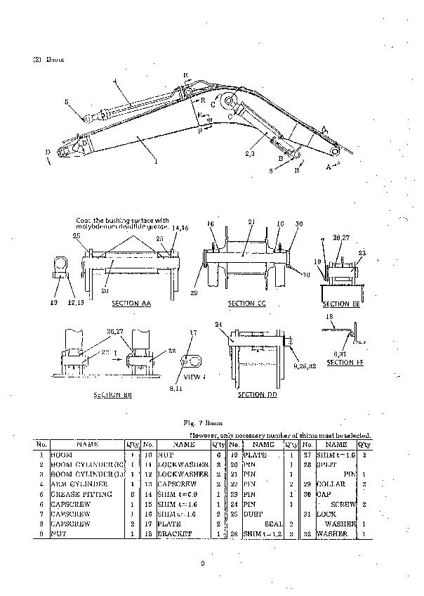
3.5 REMOVING BOOM
1) Place a sling around boom cylinder (G), lift it and remove the capscrew and nut that fasten pin (H).
2) Draw out pin (H) by the width equal to the cylinder rod boss and remove cylinder (G).
3) Remove the opposite cylinder in the same way as cylinder (G).
4) Disconnect all tubes and hoses and put a plug into each opening
5) Disconnect electric wiring of head light.
...


