Komatsu CK30-1 Loader Workshop Repair & Service Manual
Catalog:
Model:
Complete workshop manual including electrical wiring diagrams for Komatsu CK30 Loader. It's the same service manual used by dealers that guaranteed to be fully functional and intact without any missing page to save your precious time.
This repair manual (including maintenance, overhaul, disassembling & assembling, adjustment, tune-up, operation, inspecting, diagnostic & troubleshooting…) is divided into different sections. Each section covers a specific component or system with detailed illustrations. A table of contents is placed at the beginning of each section. Pages are easily found by category, and each page is expandable for great detail. The printer-ready PDF documents work like a charm on all kinds of devices.
"Shop Manual (WEBM006500).pdf"
300 pages: Komatsu CK30-1 Crawler Skid-Steer Loader Shop Manual
SERIAL NUMBERS: F00003 and UP
"Shop Manual (CEBM017100).pdf"
302 pages: Komatsu CK30-1 Compact Track Loader Shop Manual
SERIAL NUMBERS: A30001 and UP
CEAM017102 - Compact Track Loader CK30-1 Operation & Maintenance Manual (SN CK30-1 A30001&up.pdf
EXCERPT:
CONTENTS
10. STRUCTURE AND FUNCTION
20. TESTING AND ADJUSTING
30. REMOVAL AND INSTALLATION
40. MAINTENANCE STANDARD
90. OTHER
...
STRUCTURE AND FUNCTION R.H. PPC VALVE (PATTERN CHANGE) (OPTIONAL)
FUNCTION
1. Control lever in NEUTRAL position
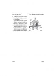
Ports P1 and P2 of the PPC valve are connected to drain chamber D through fine control hole f in spool (1). (Fig. 1).
2. During fine control (NEUTRAL o fine control)
When piston (4) starts to be pushed by disc (5), retainer (9) is pushed; spool (1) is also pushed by metering spring (2), and moves down.
When this happens, fine control hole f is shut off from drain chamber D, and at almost the same time, it is connected to pump pressure chamber PP, so pilot pressure oil from the control pump passes through fine control hole f and goes from port P1.
When the pressure at port P1 becomes higher, spool (1) is pushed back and fine control hole f is shut off from pump pressure chamber PP.
At almost the same time, it is connected to drain chamber D to release the pressure at port P1.
When this happens, spool (1) moves up or down so that the force of metering spring (2) is balanced with the pressure at port P1.
The relationship in the position of spool (1) and body (10) (fine control hole f is at a point midway between drain hole D and pump pressure chamber PP) does not change even if the pressure at port P1 becomes max.
Therefore, metering spring (2) is compressed proportionally to the amount of movement of the control lever, so the pressure at port P1 also rises in proportion to the travel of the control lever.
a) until pressures on port P1 are perfectly balanced;
b) pressure at port P1 on stem (1) reaches the value needed to counteract the force of spring (2).
This ensure proportionality between control lever position, P1 circuit pressure, and main control valve stem displacement (Fig. 2).
...


