Case 580L, 580 Super L, 590L, 590 Super L Factory Service & Shop Manual
Catalog:
Model:
Complete workshop repair service manual with Electrical Wiring Diagrams for Case 580L, 580 Super L, 590L, 590 Super L Loader Backhoe. It's the same service manual used by dealers that guaranteed to be fully functional and intact without any missing page.
This Case 580L, 580 Super L, 590L, 590 Super L Loader Backhoe service repair manual (including maintenance, overhaul, disassembling & assembling, adjustment, tune-up, operation, inspecting, diagnostic & troubleshooting…) is divided into different sections. Each section covers a specific component or system with detailed illustrations. A table of contents is placed at the beginning of each section. Pages are easily found by category, and each page is expandable for great detail. The printer-ready PDF documents work like a charm on all kinds of devices.
1,702+1,468 pages, bookmarked, Searchable, Printable, high quality PDF
7-10402 - "L" Series 2 Loader Backhoe Family (570LXT, 580L, 580 Super L, 590L, 590 Super L) Service Manual.pdf
7-48854 - "L" Series Loader Backhoe Family (580L, 580 Super L, 590L, 590 Super L) Service Manual.pdf
Case Factory Manuals. Digital PDF format with all its advantages, just like the original paper manual. Step by step Instructions, illustrations, diagrams.
PDF Manual:
Instant download: You will receive a link for download on your email immediately after payment.
Compatible with PC, MAC/ Tablet / Smartphone
Searchable PDF
Bookmarks
Printable: pages or entire manual
Zoomable: detailed exploded diagrams, picture
Models
Case 570LXT Series 2 Loader Landscaper
Contents
Service Repair Manual
General
Section Index – General
Standard Torque Specifications
Fluids and Lubricants
Loctite Product Chart
Engines
Section Index – Engine
Engine and Radiator Removal and Installation
Stall Tests
For Engine Repair, See the Engine Service Manual
Fuel System
For Fuel System Repair, See the Engine Service Manual
Electrical
Section Index – Electrical
Removal and Installation of Electrical Components
Electrical Specifications and Troubleshooting
Batteries
Starter Motor – Denso
Instrument Cluster
Alternator
Steering
Section Index – Steering
Removal and Installation of Steering Components
Steering Specifications, Pressure Checks and Troubleshooting
Steering Control Valve
Steering Cylinders
Front Axle – Two Wheel Drive
Front Axle – Four Wheel Drive
Power Train
Section Index – Power Train
Removal and Installation of Power Train Components
Standard Transmission Specifications, Pressure Checks and Troubleshooting
Wheels and Tires
Rear Axle and Planetaries – 570LXT
Standard (Carraro) Transmission
Brakes
Section Index – Brakes
Removal and Installation of Brake Components
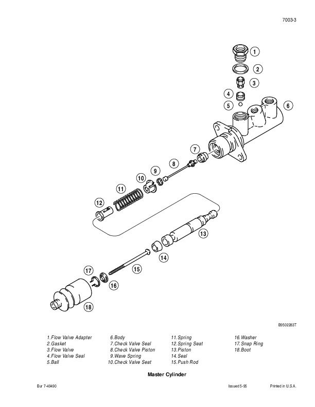
Master Cylinder
Hydraulics
Section Index – Hydraulics
Removal and Installation of Hydraulic Components
Hydraulic Specifications, Troubleshooting, and Pressure Checks
Cleaning the Hydraulic System
Hydraulic Pump – 570LXT
Loader Control Valve
Cylinders
Three Point Hitch Control Valve
Auxiliary Control Valve
Accumulator for Machines with Optional Ride Control
Solenoid Valve for Machines with Optional Ride Control
Mounted Equipment
Section Index – Mounted Equipment
Pedals and Levers
Air Conditioning Troubleshooting For Systems With R-134a Refrigerant
Air Conditioning System Gauges and Testing For Systems With R-134a Refrigerant
Air Conditioning System Service For Systems With R-134a Refrigerant
Air Conditioning Components Service For Systems With R-134a Refrigerant
Loader
ROPS Cab and Canopy
Seat Belts
Air Suspension Seat (Sears)
Suspension Seat (Milsco)
Hydraulic Schematic Foldout (570LXT)
Operator’s Manual
To The Owner
After Delivery Check
Right, Left, Front And Rear Of Machine
Identification Numbers
Machine Components
Safety/Decals/Hand Signals
Safety Features
Safety Rules
Before Operation
Machine Operation
Parking The Machine
Burn Prevention
Fire Or Explosion Prevention
Maintenance
Wheel And Tire Maintenance
Roll-Over Protection Structure
Cast Ductile Iron
Safety Decals
Hand Signals
Instruments And Controls
Instrument Cluster
Transmission Controls
Foot Pedals
Front Console Controls
Left Side Instrument Console Controls
Loader Controls
Three-Point Hitch Control
Standard Seat
Standard Suspension Seat
Seatbelts
Cab Climate Control Panel (If Equipped)
Cab And Canopy Options
Storage And Convenience Options
Table Of Contents
Operating Instructions
Run-In Period Of A New Machine
Engine Operation
Engine Starting Aids
Machine Operation
Towing A Disabled Machine
Operating In Cold Weather
Operating In Hot Weather
Loader Operation
Loader Hydraulic Coupler (Optional)
Three Point Hitch Operation
Vandal Lockup Kits
Wheels/Tires
Lubrication / Maintenance Charts
General Safety Before You Service
Engine Hourmeter
Support Strut For Loader Lift Arms
Fluids And Lubricants
Lubrication/Maintenance Chart
Systemgard Lubrication Analysis Program
Environment
Lubrication/Filters/Fluids
Opening The Engine Hood
Loader Grease Fittings
Machine Grease Fittings
Three Point Hitch Grease Fittings
Fluid Levels
Engine Oil Recommendations
Engine Service Specifications
Air Filter System
Engine Cooling System
Diesel Fuel System
Hydraulic System
Transmission
Rear Axle
Front Four Wheel Drive Axle
Cab Air Filter
Maintenance And Adjustments
Loader Return-To-Dig Adjustment
Ether Starting Aid
Fan Drive Belt Replacement
Plastic And Resin Parts
Spark Arrester Muffler (If Equipped)
Ride Control Accumulator
Cab Air Conditioning
Roll-Over Protective Structure
Fire Extinguisher
Electrical System
Batteries
Lamp Replacement
Instrument Cluster
Fuses
Accessory Outlets (If Equipped)
Machine Storage
Removal From Storage
Specifications
Engine Data (Naturally Aspirated)
Engine Data (Turbocharged)
Bolt Torques
Main Relief Valve Pressures
Travel Speeds
Operating Weights
Loader Buckets
Basic Machine Dimensions
Loader Operating Data And Dimensions
Three Point Hitch Lift Capacities
Index
After Delivery Check
EXCERPT:
MASTER CYLINDER
Removal
STEP 1
Park the machine on a level surface. Raise the loader and lock the support strut to hold the loader.
STEP 2
Apply the parking brake.
STEP 3
Open the hood.
STEP 4
Loosen the clamp for the exhaust pipe at the muffler.
Remove the exhaust pipe from the muffler.
STEP 5
Remove the tie strap (1 ). Disconnect the electrical connectors (2) for the air restriction indicator. Loosen
the clamp (3) on the air cleaner hose. Disconnect the hose from the air cleaner.
STEP 6
Remove the cap screws and flat washers that fasten the cover to the uprights. Remove the cover and air cleaner as an assembly.
STEP 7
Remove the bolts, flat washers, and insulator curtain that covers the master cylinders.
NOTE: See the illustration on page 6 for the following steps.
STEP 8
Remove any dirt from the master cylinder (1) and the area around the master cylinder (1).
…
Case 580L, 580 Super L, 590L, 590 Super L Factory Service & Shop Manual


