Caterpillar 216B, 216B2, 226B, 226B2, 232B, 232B2, 242B, 242B2 Skid Steer Loader Factory Service & Shop Manual
Catalog:
Model:
Complete workshop repair service manual with electrical wiring diagrams for Caterpillar 216B, 216B2, 226B, 226B2, 232B, 232B2, 242B, 242B2 Skid Steer Loader. It's the same service manual used by dealers that guaranteed to be fully functional and intact without any missing page.
This Caterpillar 216B, 216B2, 226B, 226B2, 232B, 232B2, 242B, 242B2 Skid Steer Loader service & repair manual (including maintenance, overhaul, disassembling & assembling, adjustment, tune-up, operation, inspecting, diagnostic & troubleshooting…) is divided into different sections. Each section covers a specific component or system with detailed illustrations. A table of contents is placed at the beginning of each section. Pages are easily found by category, and each page is expandable for great detail. The printer-ready PDF documents work like a charm on all kinds of devices.
KENR8654 - Schematic (216B2, 226B2, 232B2, 236B2 , 242B2, & 252B2 Skid Steer Loader 247B2 & 257B2 Multi-Terrain Loader Electrical System)
Collage
Main
KENR8815 - Specifications (216B2, 226B2, 232B2 & 242B2 Skid Steer Loaders Machine Systems)
Axle
Control Manifold (Quick Coupler)
Control Manifold and Solenoid (Parking Brake) 1
Control Manifold and Solenoid (Parking Brake) 2
Control Manifold and Solenoid (Work Tool Positioner)
Control Valve (Work Tool)
Coupler Cylinder
Engine Enclosure
Gas Spring Group (Cab)
Gear Motor (Fan) - Demand
Gear Motor (Fan) 1
Gear Motor (Fan) 2
Gear Pump - High Flow or Boost Flow
Gear Pump
Hydraulic Oil Filter
Hydraulic Tank
Lift Arm Cylinder and Mounting 1
Lift Arm Cylinder and Mounting 2
Lift Cylinder - Right Hand
Lift Cylinder
Machine Frame and Mounting 1
Machine Frame and Mounting 2
Motor Mounting (Hydrostatic) 3
Pilot Operated Hydraulic Control - Hydrostatic
Pilot Operated Hydraulic Control - Work Tool
Pilot Operated Hydraulic Control 1
Pilot Operated Hydraulic Control 2
Pilot Operated Hydraulic Control 3
Pilot Operated Hydraulic Control 4
Piston Motor
Piston Pump 1
Piston Pump 2
Pump Mounting (Hydrostatic) 1
Pump Mounting (Hydrostatic) 2
Quick Coupler 1
Quick Coupler 2
ROPS Mounting
Radiator and Hydraulic Oil Cooler (Fan)
Radiator and Hydraulic Oil Cooler
Return Manifold
Tandem Drive
Tilt Cylinder - Left Hand
Tilt Cylinder - Right Hand
Tire and Rim 1
Tire and Rim 2
Tire and Rim 3
KENR8816 - Systems Operation (216B2, 226B2, 232B2 & 242B2 Skid Steer Loaders Machine Systems)
Control Manifold and Solenoid (Work Tool Positioner)
Control Valve (Work Tool)
General Information
Governor Contro
Hydrostatic System
Pilot Hydraulic System
Pilot Valve (Joystick)
Piston Motor (Hydrostatic)
Piston Pump (Hydrostatic)
Tandem Drive and Axle
Work Tool Hydraulic System
KENR8817 - Testing & Adjusting (216B2, 226B2, 232B2 & 242B2 Skid Steer Loaders Machine Systems)
Accumulator (Pilot) - Test and Charge
Hydraulic Oil Contamination - Test
Hydraulic System Troubleshooting
Hydrostatic System - Flush and Fill
Hydrostatic System - Test and Adjust
Hydrostatic System Troubleshooting
Line Relief Valve - Test and Adjust
Machine Preparation
Main Relief Valve - Test and Adjust
Operational Checks
Pilot System Pressure - Test
Pump Flow - Test
System Pressure - Release
Visual Inspection
Worksheets - Troubleshoot
KENR8818 - Specifications (247B2 & 257B2 Multi Terrain Loaders Machine Systems)
Axle - Front
Axle - Rear
Bogie Wheel
Control Manifold (High Flow)
Control Manifold (Quick Coupler)
Control Manifold and Solenoid (Parking Brake)
Control Manifold and Solenoid (Work Tool Positioner)
Control Valve (Work Tool)
Coupler Cylinder
Engine Enclosure
Gas Spring Group (Cab)
Gear Motor (Fan) - Demand
Gear Motor (Fan)
Gear Pump - High Flow or Boost Flow
Gear Pump
Hydraulic Oil Filter
Hydraulic Tank
Idler Wheel 1
Idler Wheel 2
Lift Arm Cylinder and Mounting 1
Lift Arm Cylinder and Mounting 2
Lift Cylinder - Left Hand
Lift Cylinder - Right Hand
Lift Cylinder
Machine Frame and Mounting 1
Machine Frame and Mounting 2
Pilot Operated Hydraulic Control - Hydrostatic 1
Pilot Operated Hydraulic Control - Hydrostatic 2
Pilot Operated Hydraulic Control - Hydrostatic
Pilot Operated Hydraulic Control - Work Tool
Pilot Operated Hydraulic Control 1
Pilot Operated Hydraulic Control 2
Piston Motor
Piston Pump
Pump Mounting (Hydrostatic)
Quick Coupler 1
Quick Coupler 2
ROPS Mounting
Radiator and Hydraulic Oil Cooler (Fan)
Radiator and Hydraulic Oil Cooler
Return Manifold
Sprocket
Tilt Cylinder - Left Hand
Tilt Cylinder - Right Hand
Track Drive - Left Hand
Track Drive - Right Hand
Track Tensioner
Undercarriage - Left Hand
Undercarriage - Right Hand
RENR4869 - Schematic (216B, 216B2, 226B, 226B2, 232B, 232B2, 236B, 236B2, 242B, 242B2, 246B, 252B, 252B2, & 262B Skid Steer Loader Hydraulic System)
Collage
Main
RENR4893 - Disassembly & Assembly (216B, 216B2, 226B, 226B2, 232B, 232B2, 242B & 242B2 Skid Steer Loaders Engine Supplement)
Air Cleaner - Remove and Install
Alternator - Remove and Install
Battery and Battery Cable - Separate and Connect
Cab - Tilt
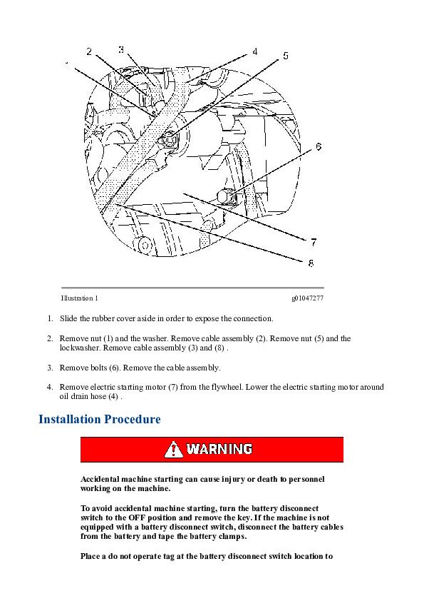
Electric Starting Motor - Remove and Install
Engine - Install
Engine - Remove
Engine Enclosure - Remove and Install
Fuel Priming Pump and Primary Filter (Water Separator) - Remove and Install
Gear Motor (Fan) - Assemble
Gear Motor (Fan) - Disassemble
Gear Motor (Fan) - Install
Gear Motor (Fan) - Remove
Hydraulic System Pressure - Release
Muffler - Remove and Install
Pump Mounting - Remove and Install
Radiator and Hydraulic Oil Cooler - Install
Radiator and Hydraulic Oil Cooler - Remove
Water Pump - Remove and Install
Water Temperature Regulator - Remove and Install
RENR4894 - Disassembly & Assembly (216B, 226B, 232B & 242B Skid Steer Loaders Power Train)
Axle - Assemble
Axle - Disassemble
Axle - Install
Axle - Remove
Chain (Drive) - Install
Chain (Drive) - Remove
Chain (Drive) Tension - Adjust
Hydraulic System Pressure - Release
Piston Motor (Hydrostatic) - Assemble
Piston Motor (Hydrostatic) - Disassemble
Piston Motor (Hydrostatic) - Install
Piston Motor (Hydrostatic) - Remove
Piston Pump (Hydrostatic) - Assemble
Piston Pump (Hydrostatic) - Disassemble
Piston Pump (Hydrostatic) - Install
Piston Pump (Hydrostatic) - Remove
Solenoid Valve and Mounting (Parking Brake) - Remove and Install - One Speed
Solenoid Valve and Mounting (Parking Brake) - Remove and Install - Two Speed
Tire and Rim - Remove and Install
RENR4895 - Specifications (216B, 226B, 232B & 242B Skid Steer Loaders Machine Systems)
Axle
Control Manifold (Quick Coupler)
Control Manifold and Solenoid (Parking Brake)
Control Valve (Work Tool) 1
Control Valve (Work Tool) 2
Coupler Cylinder
Engine Enclosure
Gas Spring Group (Cab)
Gear Motor (Fan) - Demand
Gear Motor (Fan) 1
Gear Motor (Fan) 2
Gear Pump - High Flow or Boost Flow
Gear Pump
Hydraulic Oil Filter
Hydraulic Tank
Lift Arm Cylinder and Mounting 1
Lift Arm Cylinder and Mounting 2
Lift Cylinder - Right Hand
Lift Cylinder
Machine Frame and Mounting 1
Machine Frame and Mounting 2
Motor Mounting (Hydrostatic)
Pilot Operated Hydraulic Control - Hydrostatic
Pilot Operated Hydraulic Control - Work Tool
Pilot Operated Hydraulic Control 1
Pilot Operated Hydraulic Control 2
Pilot Operated Hydraulic Control 3
Pilot Operated Hydraulic Control 4
Pilot Operated Hydraulic Control 5
Pilot Operated Hydraulic Control 6
Pilot Operated Hydraulic Control 7
Piston Motor
Piston Pump 1
Piston Pump 2
Pump Mounting (Hydrostatic) 1
Pump Mounting (Hydrostatic) 2
Quick Coupler 1
Quick Coupler 2
ROPS Mounting
Radiator and Hydraulic Oil Cooler (Fan)
Radiator and Hydraulic Oil Cooler
Return Manifold
Tandem Drive
Tilt Cylinder - Left Hand
Tilt Cylinder - Right Hand
Tire and Rim 1
Tire and Rim 2
Tire and Rim 3
RENR4896 - Systems Operation (216B, 226B, 232B & 242B Skid Steer Loaders Machine Systems)
Control Manifold and Solenoid (Work Tool Positioner)
Control Valve (Work Tool)
General Information
Governor Control
Hydrostatic System
Pilot Hydraulic System
Pilot Valve (Joystick)
Piston Motor (Hydrostatic)
Piston Pump (Hydrostatic)
Tandem Drive and Axle
Work Tool Hydraulic System
RENR4897 - Testing & Adjusting (216B, 226B, 232B & 242B Skid Steer Loaders Machine Systems)
Accumulator (Pilot) - Test and Charge
Hydraulic Oil Contamination - Test
Hydraulic System Troubleshooting
Hydrostatic System - Flush and Fill
Hydrostatic System - Test and Adjust
Hydrostatic System Troubleshooting
Line Relief Valve - Test and Adjust
Machine Preparation
Main Relief Valve - Test and Adjust
Operational Checks
Pilot System Pressure - Test
Pump Flow - Test
System Pressure - Release
Visual Inspection
Worksheets - Troubleshoot
RENR4898 - Disassembly & Assembly (216B, 216B2, 226B, 226B2, 232B, 232B2, 242B & 242B2 Skid Steer Loaders Machine Systems)
Accumulator - Remove and Install
Air Conditioner and Heater - Assemble
Air Conditioner and Heater - Disassemble
Air Conditioner and Heater - Install
Air Conditioner and Heater - Remove
Cab - Install
Cab - Remove
Cab - Tilt
Control Valve (Work Tool) - Assembl
Control Valve (Work Tool) - Disassemble
Control Valve (Work Tool) - Install
Control Valve (Work Tool) - Remove
Coupler Cylinder - Remove and Install
Disconnecting Snap To Connect Fittings
Diverter Valve - Install
Diverter Valve - Remove
Gas Spring - Remove and Install
Gear Motor - Assemble
Gear Motor - Disassemble
Gear Motor - Install
Gear Motor - Remove
Gear Pump - Assemble
Gear Pump - Disassemble
Gear Pump - Install
Gear Pump - Remove
Hydraulic System Pressure - Release
Hydraulic Tank - Install
Hydraulic Tank - Remove
Lift Arms - Install
Lift Arms - Remove
Lift Cylinder - Install
Lift Cylinder - Remove
Pilot Operated Hydraulic Control - Assemble
Pilot Operated Hydraulic Control - Disassemble
Pilot Operated Hydraulic Control - Install
Pilot Operated Hydraulic Control - Remove
Quick Coupler - Remove and Install
Refrigerant Accumulator - Remove and Install
Refrigerant Compressor and Support Housing - Remove and Install
Refrigerant Condenser and Mounting - Remove and Install
Seat - Remove and Install
Solenoid Valve (Compressor Motor) - Remove and Install
Solenoid Valve and Mounting (Coupler) - Remove and Install
Tilt Cylinder - Install
Tilt Cylinder - Remove
Window Wiper Motor - Remove and Install
RENR6417 - Systems Operation (247B, 257B, 267B, 277B & 287B Multi Terrain Loaders & 216B, 226B, 232B, 236B, 242B, 246B, 248B, 252B, 262B & 268B Skid Steer Loaders Interlock Electronic Control System)
Diagnostic Operation
Electronic Control Module (ECM)
Engine Start Interlock
General Information
Hydrostatic System Interlock and Parking Brake Interlock
Indicators
Normal Operation
Related Components
Relays
Solenoid Valve
Switches
Work Tool Interlock
RENR6417 - Testing & Adjusting (247B, 257B, 267B, 277B & 287B Multi Terrain Loaders & 216B, 226B, 232B, 236B, 242B, 246B, 248B, 252B, 262B & 268B Skid Steer Loaders Interlock Electronic Control System)
Electronic Control Module (ECM) - Replace
Glossary of Electrical Terms
System Schematic
RENR6417 - Troubleshooting (247B, 257B, 267B, 277B & 287B Multi Terrain Loaders & 216B, 226B, 232B, 236B, 242B, 246B, 248B, 252B, 262B & 268B Skid Steer Loaders Interlock Electronic Control System)
Armrest Indicator Is Flashing
Charging System
Electrical Component and Connector Locations
Electrical System
Engine Does Not Crank
General Information
Initial Troubleshooting Procedure
Parking Brake Indicator Is Flashing
Parking Brake Indicator and Armrest Indicator Are Flashing
Parking Brake Indicator and Armrest Indicator Do Not Function Correctly
Parking Brake Intermittent
Service Tools
Solenoid Valve (Parking Brake) Does Not Function Correctly
Switch (Hydraulic Lockout)
Switch (Parking Brake)
Work Tool Does Not Function
RENR6418 - Systems Operation (247B, 257B, 267B, 277B & 287B Multi Terrain Loaders & 216B, 226B, 232B, 236B, 242B, 246B, 248B, 252B, 262B & 268B Skid Steer Loaders Auxiliary Hydraulic Electronic Control System)
Cat Data Link
Electronic Control Module (ECM)
General Information
Indicators
Normal Operation
Related Components
Sensors
Solenoid Valves
Switches
RENR6418 - Testing & Adjusting (247B, 257B, 267B, 277B & 287B Multi Terrain Loaders & 216B, 226B, 232B, 236B, 242B, 246B, 248B, 252B, 262B & 268B Skid Steer Loaders Auxiliary Hydraulic Electronic Control System)
Electrical Connector - Inspect
Electronic Control Module (ECM) - Flash Program
Electronic Control Module (ECM) - Replace
Glossary of Electrical Terms
System Schematic
Wiring Harness (Open Circuit) - Test
Wiring Harness (Short Circuit) - Test
RENR6418 - Troubleshooting (247B, 257B, 267B, 277B & 287B Multi Terrain Loaders & 216B, 226B, 232B, 236B, 242B, 246B, 248B, 252B, 262B & 268B Skid Steer Loaders Auxiliary Hydraulic Electronic Control System)
Auxiliary Hydraulic Does Not Function in Either Direction
Auxiliary Hydraulic Does Not Function in One Direction
Diagnostic Capabilities
Diagnostic Code List
Electrical Component and Connector Locations
General Information
High Flow Does Not Function in Either Direction
High Flow Does Not Function in One Direction
Power Supply Circuit of Electronic Control Module
Service Tools
Switch (Armrest) and Switch (Seat)
Switch (Continuous Flow)
Switch (Hydraulic Lockout)
Switch (Interlock Override)
Switch (Parking Brake)
Switch (Two Speed)
Using Caterpillar Electronic Technician to Determine Diagnostic Codes
RENR6419 - Schematic (Skid Steer Loaders_216B, 216B2, 226B, 226B2, 232B, 232B2, 236B, 236B2, 242B, 242B2, 246B, 248B, 252B, 252B2, 262B, 268B_Multi Terrain Loaders_247B, 247B2, 257B, 257B2, 267B, 277B, 287B Electrical System)
Collage
Main
SEBP3770 - Parts Manual (216B, 226B, 232B, 242B Skid Steer Loader) (BXM1-Up, MJH1-Up, RLL1-Up, SCH1-Up, CSD1-Up, GGA1-Up)
...
EXCERPT:
Disassembly and Assembly
Pilot Operated Hydraulic Control - Assemble
Assembly Procedure
Note: Cleanliness is an important factor. Before assembly, all parts should be thoroughly cleaned in cleaning fluid. Allow the parts to air dry. Wiping cloths or rags should not be used to dry parts. Lint may be deposited on the parts which may cause later trouble. Inspect all parts. If any parts are worn or damaged, use new parts for replacement.
Install nut (6). Install lever (8). Tighten nut (7). Install fittings (3). Install solenoid (5) and bolt (4). Install coil assembly (10) and bolt (9).
Install rubber boot (2) onto the joystick. Install the joystick handle (1). Install the screws on the side of joystick handle.
End By: Install the pilot operated hydraulic control. Refer to Disassembly and Assembly, "Pilot Operated Hydraulic Control - Install".
…


