John Deere 200CLC, 230CLC, and 270CLC Excavator Operation & Test Technical Manual [TM1930]
Catalog:
Model:
Complete workshop repair service manual with electrical wiring diagrams for John Deere 200CLC, 230CLC, and 270CLC Excavators. It's the same service manual used by dealers that guaranteed to be fully functional and intact without any missing page.
John Deere 200CLC, 230CLC, and 270CLC Excavator Operation & Test Technical Manual (including maintenance, overhaul, disassembling & assembling, adjustment, tune-up, operation, inspecting, diagnostic & troubleshooting…) is divided into different sections. Each section covers a specific component or system with detailed illustrations. A table of contents is placed at the beginning of each section. Pages are easily found by category, and each page is expandable for great detail. The printer-ready PDF documents work like a charm on all kinds of devices.
TM1930 - John Deere 200CLC, 230CLC, and 270CLC Excavator Operation & Test Technical Manual.pdf
tm10048 - John Deere Экскаваторов 200CLC, 230CLC и 270CLC.pdf
tm2922 - John Deere Excavatrices 200CLC, 230CLC et 270CLC.pdf
tm2943 - John Deere Excavadoras 200CLC, 230CLC, y 270CLC.pdf
Category: Operation and Test
Language: Spanish Russian English French
TABLE OF CONTENTS
Foreword....0
Technical Information Feedback Form....0
Section 9000: General Information....0
Group 01: Safety....0
Recognize Safety Information....0
Follow Safety Instructions....0
Operate Only If Qualified....0
Wear Protective Equipment....0
Avoid Unauthorized Machine Modifications....0
Add Cab Guarding for Special Uses....0
Inspect Machine....0
Stay Clear of Moving Parts....0
Avoid High-Pressure Oils....0
Beware of Exhaust Fumes....0
Prevent Fires....0
Prevent Battery Explosions....0
Handle Chemical Products Safely....0
Dispose of Waste Properly....0
Prepare for Emergencies....0
Use Steps and Handholds Correctly....0
Start Only From Operator's Seat....0
Use and Maintain Seat Belt....0
Prevent Unintended Machine Movement....0
Avoid Work Site Hazards....0
Keep Riders Off Machine....0
Avoid Backover Accidents....0
Avoid Machine Tip Over....0
Use Special Care When Lifting Objects....0
Add and Operate Attachments Safely....0
Park and Prepare for Service Safely....0
Service Cooling System Safely....0
Remove Paint Before Welding or Heating....0
Make Welding Repairs Safely....0
Drive Metal Pins Safely....0
Recognize Safety Information....0
Recognize Safety Information....0
Follow Safety Instructions....0
Operate Only If Qualified....0
Wear Protective Equipment....0
Avoid Unauthorized Machine Modifications....0
Add Cab Guarding for Special Uses....0
Inspect Machine....0
Stay Clear of Moving Parts....0
Avoid High-Pressure Oils....0
Beware of Exhaust Fumes....0
Prevent Fires....0
Prevent Battery Explosions....0
Handle Chemical Products Safely....0
Dispose of Waste Properly....0
Prepare for Emergencies....0
Use Steps and Handholds Correctly....0
Start Only From Operator's Seat....0
Use and Maintain Seat Belt....0
Prevent Unintended Machine Movement....0
Avoid Work Site Hazards....0
Keep Riders Off Machine....0
Avoid Backover Accidents....0
Avoid Machine Tip Over....0
Use Special Care When Lifting Objects....0
Add and Operate Attachments Safely....0
Park and Prepare for Service Safely....0
Service Cooling System Safely....0
Remove Paint Before Welding or Heating....0
Make Welding Repairs Safely....0
Drive Metal Pins Safely....0
Section 9005: Operational Checkout Procedure....0
Group 10: Operational Checkout Procedure....0
Operational Checkout....0
Operational Checkout....0
Operational Checkout....0
Section 9010: Engine....0
Group 05: Theory of Operation....0
Engine Speed Control System Operation....0
Group 15: Diagnostic Information....0
Diagnose Engine Malfunctions—200CLC (S.N. —504000), 230CLC and 270CLC....0
Diagnose Engine Malfunctions—200CLC (S.N. 504001—)....0
Group 25: Tests....0
Engine Speed Test....0
Fuel Line Leakage Test....0
Engine Power Test Using Turbocharger Boost Pressure....0
Engine Speed Control System Operation....0
Engine RPM Dial....0
Hydraulic Oil Warm-Up....0
Engine Speed Control System Operation....0
Engine RPM Dial....0
Hydraulic Oil Warm-Up....0
Diagnose Engine Malfunctions—200CLC (S.N. —504000), 230CLC and 270CLC....0
Diagnose Engine Malfunctions—200CLC (S.N. —504000), 230CLC and 270CLC....0
Diagnose Engine Malfunctions—200CLC (S.N. 504001—)....0
Engine Speed Test....0
Engine Speed Test....0
Fuel Line Leakage Test....0
Engine Power Test Using Turbocharger Boost Pressure....0
Section 9015: Electrical System....0
Group 05: System Information....0
Electrical Diagram Information....0
Group 10: System Diagrams....0
Explanation of Wire Markings....0
Fuse Specifications....0
System Functional Schematic, Component Location, and Wiring Diagram Master Legend....0
System Functional Schematic....0
Cab Harness (W1) Component Location....0
Cab Harness (W1) Wiring Diagram....0
Machine Harness (W2) Component Location....0
Machine Harness (W2) Wiring Diagram....0
Monitor Harness (W3) Component Location....0
Monitor Harness (W3) Wiring Diagram....0
Air Conditioner and Heater Harness (W7) Component Location....0
Air Conditioner and Heater Harness (W7) Wiring Diagram....0
Pump Harness (W12) Component Location....0
Pump Harness (W12) Wiring Diagram....0
Engine Harness (W18) Component Location — 200CLC (S.N. —504000), 230CLC, and 270CLC....0
Engine Harness (W18) Wiring Diagram — 200CLC (S.N. —504000), 230CLC, and 270CLC....0
Engine Control Unit Harness (W19) Component Location — 200CLC (S.N. —504000), 230CLC, and 270CLC....0
Engine Control Unit Harness (W19) Wiring Diagram — 200CLC (S.N. —504000), 230CLC, and 270CLC....0
Engine Harness (W22) Component Location — 200CLC (S.N. 504001—)....0
Engine Harness (W22) Wiring Diagram — 200CLC (S.N. 504001—)....0
Engine Control Unit Harness (W23) Component Location — 200CLC (S.N. 504001—)....0
Engine Control Unit Harness (W23) Wiring Diagram — 200CLC (S.N. 504001—)....0
Group 15: Sub-System Diagnostics....0
Starting and Charging Circuit Theory of Operation....0
Propel Alarm Circuit Theory of Operation....0
Monitor Controller and Display Circuit Theory of Operation....0
Engine Control Unit Circuit Theory of Operation — 200CLC (S.N. —504000), 230CLC, and 270CLC....0
Engine Control Unit Circuit Theory of Operation — 200CLC (S.N. 504001—)....0
Pump and Valve Controller Circuit Theory of Operation....0
Windshield Wiper and Washer Circuit Theory of Operation....0
Air Conditioner and Heater Controller Circuit Theory of Operation....0
Group 20: References....0
Diagnostic Display Unit Operation....0
Excavator Diagnostic Program General Description and Overview....0
Reading Diagnostic Trouble Codes Without Laptop Computer....0
Engine Diagnostic Trouble Codes — 200CLC (S.N. —504000), 230CLC and 270CLC....0
Engine Diagnostic Trouble Codes — 200CLC (S.N. 504001—)....0
Pump and Valve Controller Diagnostic Trouble Codes....0
Monitor Display Diagnostic System Operation....0
Monitor Data Items....0
Alternator Test Procedure....0
Fuse Test....0
Relay Test....0
Pressure Sensor Test....0
Solenoid Test....0
Temperature Sensor Test....0
Engine Speed (N) Sensor Test....0
Electrical Component Checks....0
Battery Remove and Install....0
Rear Cover Remove and Install....0
Machine Information Center (MIC) Remove and Install....0
Pump and Valve Controller (PVC) Remove and Install....0
Engine Control Unit (ECU) Remove and Install....0
Key Switch Remove and Install....0
Propel Alarm Cancel Switch Remove and Install....0
Propel Alarm Remove and Install....0
Windshield Wiper Enable Switch Remove and Install....0
Switch Panel (A4) Remove and Install....0
Monitor Controller and Display (A5) Remove and Install....0
Disconnect Tab Retainer Connectors....0
Disconnecting Spring Wire Clip Connectors....0
Replace DEUTSCH DEUTSCH is a trademark of the Deutsch Co. Connectors....0
Install DEUTSCH DEUTSCH is a trademark of the Deutsch Co. Contacts....0
Replace WEATHER PACK WEATHER PACK is a trademark of Packard Electric. Connector....0
Install WEATHER PACK WEATHER PACK is a trademark of Packard Electric. Contacts....0
Replace (Pull Type) Metri-Pack™ Connectors....0
Replace (Push Type) Metri-Pack™ Connectors....0
Remove Connector Body from Blade Terminals....0
Electrical Diagram Information....0
System Functional Schematic Diagram....0
Wiring Diagram—If Provided....0
Component Location Diagram....0
Connector End View Diagram—If Provided....0
Electrical Schematic Symbols....0
Electrical Diagram Information....0
System Functional Schematic Diagram....0
Wiring Diagram—If Provided....0
Component Location Diagram....0
Connector End View Diagram—If Provided....0
Electrical Schematic Symbols....0
Explanation of Wire Markings....0
Explanation of Wire Markings....0
Fuse Specifications....0
System Functional Schematic, Component Location, and Wiring Diagram Master Legend....0
System Functional Schematic....0
Cab Harness (W1) Component Location....0
Cab Harness (W1) Wiring Diagram....0
Machine Harness (W2) Component Location....0
Machine Harness (W2) Wiring Diagram....0
Monitor Harness (W3) Component Location....0
Monitor Harness (W3) Wiring Diagram....0
Air Conditioner and Heater Harness (W7) Component Location....0
Air Conditioner and Heater Harness (W7) Wiring Diagram....0
Pump Harness (W12) Component Location....0
Pump Harness (W12) Wiring Diagram....0
Engine Harness (W18) Component Location — 200CLC (S.N. —504000), 230CLC, and 270CLC....0
Engine Harness (W18) Wiring Diagram — 200CLC (S.N. —504000), 230CLC, and 270CLC....0
Engine Control Unit Harness (W19) Component Location — 200CLC (S.N. —504000), 230CLC, and 270CLC....0
Engine Control Unit Harness (W19) Wiring Diagram — 200CLC (S.N. —504000), 230CLC, and 270CLC....0
Engine Harness (W22) Component Location — 200CLC (S.N. 504001—)....0
Engine Harness (W22) Wiring Diagram — 200CLC (S.N. 504001—)....0
Engine Control Unit Harness (W23) Component Location — 200CLC (S.N. 504001—)....0
Engine Control Unit Harness (W23) Wiring Diagram — 200CLC (S.N. 504001—)....0
Starting and Charging Circuit Theory of Operation....0
Start Circuit....0
Charging Circuit....0
Starting and Charging Circuit Theory of Operation....0
Start Circuit....0
Charging Circuit....0
Propel Alarm Circuit Theory of Operation....0
Monitor Controller and Display Circuit Theory of Operation....0
HOUR METER AND GAUGES....0
STATUS INDICATORS....0
Air Filter Restriction Indicator Light....0
Fuel Level Indicator Light....0
Engine Coolant Temperature Indicator Light....0
Engine Coolant Temperature Gauge....0
Engine Oil Pressure Indicator Light....0
Engine Coolant Level Indicator Light....0
Engine Oil Level Indicator Light....0
Alternator Voltage Indicator....0
Monitor Controller and Display Alarm....0
Check Engine Indicator Light....0
CONTROL SWITCHES AND INDICATORS....0
Windshield Wiper and Washer Switch (S9)....0
Work Light Switch (S6)....0
Propel Speed Switch (S8)....0
Auto-Idle/Auto-Acceleration Switch (S13)....0
Engine RPM Dial (R10)....0
Power Mode Switch (S12)....0
Engine Control Unit Circuit Theory of Operation — 200CLC (S.N. —504000), 230CLC, and 270CLC....0
Engine Control Unit....0
Engine Speed Control....0
Power Limiting....0
Engine Control Unit Circuit Theory of Operation — 200CLC (S.N. 504001—)....0
Engine Control Unit....0
Engine Speed Control....0
Power Limiting....0
Pump and Valve Controller Circuit Theory of Operation....0
Pump and Valve Controller (A7)....0
A/I (Auto-Idle) Mode....0
A/A (Auto-Acceleration) Mode....0
Hydraulic Oil Warm-Up Circuit....0
Propel Speed Change Solenoid....0
Arm Regenerative Solenoid....0
Power Boost Solenoid....0
Swing Priority Solenoid....0
Windshield Wiper and Washer Circuit Theory of Operation....0
Windshield Wiper Continuous Operation....0
Windshield Wiper Intermittent Operation....0
Windshield Wiper Park Operation....0
Windshield Washer Operation....0
Air Conditioner and Heater Controller Circuit Theory of Operation....0
Diagnostic Display Unit Operation....0
Accessing Menu....0
Viewing Active Diagnostic Trouble Codes....0
Access Stored Codes....0
Clearing Active Or Stored Diagnostic Trouble Codes From Diagnostic Display Unit Memory....0
Diagnostic Display Unit Operation....0
Accessing Menu....0
Viewing Active Diagnostic Trouble Codes....0
Access Stored Codes....0
Clearing Active Or Stored Diagnostic Trouble Codes From Diagnostic Display Unit Memory....0
Excavator Diagnostic Program General Description and Overview....0
Troubleshooting....0
Reading Diagnostic Trouble Codes Without Laptop Computer....0
Engine Diagnostic Trouble Codes — 200CLC (S.N. —504000), 230CLC and 270CLC....0
Engine Diagnostic Trouble Codes — 200CLC (S.N. 504001—)....0
Pump and Valve Controller Diagnostic Trouble Codes....0
Monitor Display Diagnostic System Operation....0
Monitor Data Items....0
Alternator Test Procedure....0
12 V System....0
24 V System....0
Fuse Test....0
Relay Test....0
Pressure Sensor Test....0
Pressure Sensor Resistance Test....0
Pressure Sensor Voltage Test....0
Solenoid Test....0
Temperature Sensor Test....0
Engine Speed (N) Sensor Test....0
Electrical Component Checks....0
Battery Remove and Install....0
Rear Cover Remove and Install....0
Machine Information Center (MIC) Remove and Install....0
Pump and Valve Controller (PVC) Remove and Install....0
Engine Control Unit (ECU) Remove and Install....0
Key Switch Remove and Install....0
Propel Alarm Cancel Switch Remove and Install....0
Propel Alarm Remove and Install....0
Windshield Wiper Enable Switch Remove and Install....0
Switch Panel (A4) Remove and Install....0
Monitor Controller and Display (A5) Remove and Install....0
Disconnect Tab Retainer Connectors....0
Disconnecting Spring Wire Clip Connectors....0
Replace DEUTSCH™ Connectors....0
Install DEUTSCH™ Contacts....0
Replace WEATHER PACK™ Connector....0
Install WEATHER PACK™ Contacts....0
Replace (Pull Type) Metri-Pack™ Connectors....0
Replace (Push Type) Metri-Pack™ Connectors....0
Remove Connector Body from Blade Terminals....0
Section 9020: Power Train....0
Group 05: Theory of Operation....0
Track Adjuster and Recoil Spring Operation....0
Propel Gearbox Operation—200CLC and 230CLC....0
Propel Gearbox Operation—270CLC....0
Group 15: Diagnostic Information....0
Diagnose Undercarriage Components Malfunctions....0
Measure Swing Bearing Wear....0
Track Adjuster and Recoil Spring Operation....0
Track Adjuster and Recoil Spring Operation....0
Propel Gearbox Operation—200CLC and 230CLC....0
Propel Gearbox Operation—270CLC....0
Diagnose Undercarriage Components Malfunctions....0
Diagnose Undercarriage Components Malfunctions....0
Measure Swing Bearing Wear....0
Section 9025: Hydraulic System....0
Group 05: Theory of Operation....0
Hydraulic System Diagram and Operation....0
Pilot System Diagram and Operation....0
Pilot Pump, Pressure Regulating Valve and Filter Operation....0
Pilot Control Shut-Off Valve Operation....0
Pilot Controller Operation....0
Propel Pilot Controller Operation....0
Pilot Operation of Control Valve Operation....0
Pilot Signal Manifold Operation....0
Pump and Drive Gearbox Operation....0
Hydraulic Pump Regulator Operation....0
Engine Speed Sensing Control Circuit Operation....0
Control Valve Operation....0
Control Valve Check Valves Identification And Operation....0
System Relief and Power Boost Valve Circuit Operation....0
Circuit Relief Valve Operation....0
Propel Flow Combiner Valve Operation....0
Arm Regenerative Valve Circuit Operation....0
Bucket and Boom Regenerative Valve Circuit Operation....0
Boom and Arm Reduced Leakage Valves Operation....0
Swing Priority Flow Rate Valve Circuit Operation — 200CLC (S.N. —503485), 230CLC (S.N. —603182), and 270CLC (S.N. —071103)....0
Swing Priority Flow Rate Valve Circuit Operation — 200CLC (S.N. 503486—), 230CLC (S.N. 603183—), and 270CLC (S.N. 071104—)....0
Bucket Flow Rate Valve Circuit Operation....0
Swing Gearbox Operation....0
Swing Motor, Crossover Relief Valve, and Make-Up Check Valve Operation—200CLC and 230CLC....0
Swing Motor, Crossover Relief Valve, and Make-Up Check Valve Operation—270CLC....0
Swing Motor Park Brake Release Circuit Operation—200CLC and 230CLC....0
Swing Motor Park Brake Release Circuit Operation—270CLC....0
Rotary Manifold Operation....0
Propel Motor Operation—200CLC and 230CLC....0
Propel Motor Operation—270CLC....0
Propel Motor Speed Circuit Operation—200CLC and 230CLC....0
Propel Motor Speed Circuit Operation—270CLC....0
Cylinder Operation....0
Return Filter Operation....0
Hydraulic System Circuit Symbols....0
Hydraulic System Schematic....0
Group 15: Diagnostic Information....0
Diagnose Electronic and Control Valve Component Malfunctions....0
Diagnose Hydraulic System Malfunctions....0
Diagnose Pilot Circuit Malfunctions....0
Diagnose Dig Circuit Malfunctions....0
Diagnose Swing Circuit Malfunctions....0
Diagnose Propel System Malfunctions....0
Control Valve Line Identification....0
Main Hydraulic System Component Location....0
Pilot Controllers-to-Pilot Signal Manifold Component Location—Excavator Pattern....0
Pilot Controllers-to-Pilot Signal Manifold Component Location—Backhoe Pattern....0
Pilot Signal Manifold-to-Control Valve Line Connection — 200CLC (S.N. —503485), 230CLC (S.N. —603182), 270CLC (S.N. —071103)....0
Pilot Signal Manifold-to-Control Valve Line Connection — 200CLC (S.N. 503486—), 230CLC (S.N. 603183—), 270CLC (S.N. 071104—)....0
Propel System Component Location....0
Group 25: Tests....0
JT05801 Clamp-On Electronic Tachometer Installation....0
JT05800 Digital Thermometer Installation....0
JT02156A Digital Pressure/Temperature Analyzer Installation....0
Hydraulic Oil Filter Inspection Procedure....0
Hydraulic Oil Cleanup Procedure Using Portable Filter Caddy....0
Hydraulic System Warm-Up Procedure....0
Cylinder Drift Test—Boom, Arm, and Bucket....0
Pilot Pressure Regulating Valve Test and Adjustment....0
Valve Spool Actuating Pilot Pressure Test....0
System Relief and Power Boost Valve Test and Adjustment....0
Circuit Relief Valve Test and Adjustment....0
Swing Motor Crossover Relief Valve Test and Adjustment—200CLC and 230CLC....0
Swing Motor Crossover Relief Valve Test and Adjustment—270CLC....0
Propel Motor Crossover Relief Valve Test and Adjustment—200CLC and 230CLC....0
Propel Motor Crossover Relief Valve Test and Adjustment—270CLC....0
Power Boost, Propel Speed, Swing Priority, and Arm Regenerative Solenoid Valve Test and Adjustment....0
Hydraulic Pump Regulator Test and Adjustment—Minimum Flow—200CLC....0
Hydraulic Pump Regulator Test and Adjustment—Minimum Flow—230CLC....0
Hydraulic Pump Regulator Test and Adjustment—Minimum Flow—270CLC....0
Hydraulic Pump Regulator Test and Adjustment—Maximum Flow—200CLC....0
Hydraulic Pump Regulator Test and Adjustment—Maximum Flow—230CLC....0
Hydraulic Pump Regulator Test and Adjustment—Maximum Flow—270CLC....0
Hydraulic Pump Regulator Test and Adjustment—Engine Pulldown—200CLC....0
Hydraulic Pump Regulator Test and Adjustment—Engine Pulldown—230CLC....0
Hydraulic Pump Regulator Test and Adjustment—Engine Pulldown—270CLC....0
Hydraulic Pump Flow Test—200CLC and 230CLC....0
Hydraulic Pump Flow Test—270CLC....0
Swing Motor Leakage Test—200CLC and 230CLC....0
Swing Motor Leakage Test—270DLC....0
Propel Motor Leakage Test—200CLC and 230CLC....0
Travel Motor Leakage Test—270DLC....0
Hydraulic System Diagram and Operation....0
Hydraulic System Diagram and Operation....0
Pilot System Diagram and Operation....0
Pilot Pump, Pressure Regulating Valve and Filter Operation....0
Pilot Control Shut-Off Valve Operation....0
Pilot Controller Operation....0
Propel Pilot Controller Operation....0
Pilot Operation of Control Valve Operation....0
Pilot Signal Manifold Operation....0
Boom Down Flow Regulator Valve (17)....0
Bucket Flow Rate Pilot Valve (18)....0
Hydraulic Pump 1 Flow Rate Pilot Valve (22) and Hydraulic Pump 2 Flow Rate Pilot Valve (19)....0
Propel Flow Combiner Valve Pilot Valve (20)....0
Swing Park Brake Release Pilot Valve (21)....0
Swing Priority Flow Rate Pilot Valve (23)....0
Shuttle Valves (24—40)....0
Warm-Up Circuit Operation....0
Pump and Drive Gearbox Operation....0
Hydraulic Pump Regulator Operation....0
Hydraulic Pump Regulator Component Identification....0
Hydraulic Pump Regulator Control by Flow Rate Pilot Valve....0
Hydraulic Pump Regulator Control By Supply Oil Pressure....0
Hydraulic Pump Regulator Control By Speed Sensing Pilot Oil....0
Engine Speed Sensing Control Circuit Operation....0
Speed Sensing Control....0
Slow Speed Sensing....0
Control Valve Operation....0
Control Valve Component Identification....0
Control Valve Neutral and Power Passages Operation....0
Control Valve Check Valves Identification And Operation....0
System Relief and Power Boost Valve Circuit Operation....0
System Relief and Power Boost Valve....0
Power Boost Circuit Operation....0
Auto-Power Boost Operation....0
Power Boost Solenoid Valve (SG) Operation....0
Circuit Relief Valve Operation....0
Propel Flow Combiner Valve Operation....0
Arm Regenerative Valve Circuit Operation....0
Arm Regenerative Solenoid Valve (SC) Operation....0
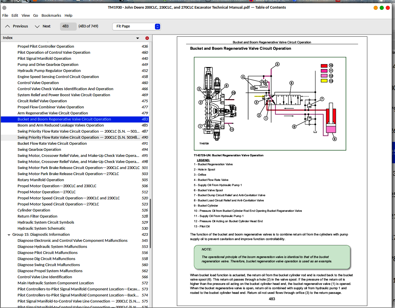
Bucket and Boom Regenerative Valve Circuit Operation....0
Boom and Arm Reduced Leakage Valves Operation....0
Swing Priority Flow Rate Valve Circuit Operation — 200CLC (S.N. —503485), 230CLC (S.N. —603182), and 270CLC (S.N. —071103)....0
Swing Priority Solenoid Valve (SE)....0
Swing Priority Flow Rate Valve Circuit Operation — 200CLC (S.N. 503486—), 230CLC (S.N. 603183—), and 270CLC (S.N. 071104—)....0
Bucket Flow Rate Valve Circuit Operation....0
Swing Gearbox Operation....0
Swing Motor, Crossover Relief Valve, and Make-Up Check Valve Operation—200CLC and 230CLC....0
Swing Motor....0
Swing Motor Crossover Relief Valve....0
Swing Motor Make-Up Valve....0
Swing Motor, Crossover Relief Valve, and Make-Up Check Valve Operation—270CLC....0
Swing Motor....0
Swing Motor Crossover Relief Valve....0
Swing Motor Make-Up Valve....0
Swing Motor Park Brake Release Circuit Operation—200CLC and 230CLC....0
Swing Motor Park Brake Release Circuit Operation—270CLC....0
Rotary Manifold Operation....0
Propel Motor Operation—200CLC and 230CLC....0
Propel Motor....0
Propel Motor Park Brake and Release Circuit....0
Propel Motor Fast and Slow Speed Change....0
Propel Motor Crossover Relief and Check Valves....0
Propel Motor Counterbalance Valve....0
Propel Motor Operation—270CLC....0
Propel Motor....0
Propel Motor Valve Housing Operation....0
Propel Motor Park Brake and Release Circuit....0
Propel Motor Fast and Slow Speed Change....0
Propel Motor Crossover Relief and Check Valves....0
Propel Motor Counterbalance Valve....0
Propel Motor Speed Circuit Operation—200CLC and 230CLC....0
Propel Motor Slow Speed Operation....0
Propel Motor Fast Speed Operation....0
Propel Speed Solenoid Valve (SI)....0
Propel Motor Speed Circuit Operation—270CLC....0
Propel Motor Slow Speed Operation....0
Propel Motor Fast Speed Operation....0
Propel Speed Solenoid Valve (SI)....0
Cylinder Operation....0
Return Filter Operation....0
Hydraulic System Circuit Symbols....0
Hydraulic System Schematic....0
Diagnose Electronic and Control Valve Component Malfunctions....0
Diagnose Electronic and Control Valve Component Malfunctions....0
Diagnose Hydraulic System Malfunctions....0
Diagnose Pilot Circuit Malfunctions....0
Diagnose Dig Circuit Malfunctions....0
Diagnose Swing Circuit Malfunctions....0
Diagnose Propel System Malfunctions....0
Control Valve Line Identification....0
Main Hydraulic System Component Location....0
Pilot Controllers-to-Pilot Signal Manifold Component Location—Excavator Pattern....0
Pilot Controllers-to-Pilot Signal Manifold Component Location—Backhoe Pattern....0
Pilot Signal Manifold-to-Control Valve Line Connection — 200CLC (S.N. —503485), 230CLC (S.N. —603182), 270CLC (S.N. —071103)....0
Pilot Signal Manifold-to-Control Valve Line Connection — 200CLC (S.N. 503486—), 230CLC (S.N. 603183—), 270CLC (S.N. 071104—)....0
Propel System Component Location....0
JT05801 Clamp-On Electronic Tachometer Installation....0
JT05801 Clamp-On Electronic Tachometer Installation....0
JT05800 Digital Thermometer Installation....0
JT02156A Digital Pressure/Temperature Analyzer Installation....0
Hydraulic Oil Filter Inspection Procedure....0
Hydraulic Oil Cleanup Procedure Using Portable Filter Caddy....0
Hydraulic System Warm-Up Procedure....0
Cylinder Drift Test—Boom, Arm, and Bucket....0
Pilot Pressure Regulating Valve Test and Adjustment....0
Valve Spool Actuating Pilot Pressure Test....0
System Relief and Power Boost Valve Test and Adjustment....0
Circuit Relief Valve Test and Adjustment....0
Swing Motor Crossover Relief Valve Test and Adjustment—200CLC and 230CLC....0
Swing Motor Crossover Relief Valve Test and Adjustment—270CLC....0
Propel Motor Crossover Relief Valve Test and Adjustment—200CLC and 230CLC....0
Propel Motor Crossover Relief Valve Test and Adjustment—270CLC....0
Propel Motor Crossover Relief Valve Test and Adjustment—270CLC (S.N. —082518)....0
Propel Motor Crossover Relief Valve Test and Adjustment—270CLC (S.N. 082519— )....0
Power Boost, Propel Speed, Swing Priority, and Arm Regenerative Solenoid Valve Test and Adjustment....0
Hydraulic Pump Regulator Test and Adjustment—Minimum Flow—200CLC....0
Hydraulic Pump Regulator Test and Adjustment—Minimum Flow—230CLC....0
Hydraulic Pump Regulator Test and Adjustment—Minimum Flow—270CLC....0
Hydraulic Pump Regulator Test and Adjustment—Maximum Flow—200CLC....0
Hydraulic Pump Regulator Test and Adjustment—Maximum Flow—230CLC....0
Hydraulic Pump Regulator Test and Adjustment—Maximum Flow—270CLC....0
Hydraulic Pump Regulator Test and Adjustment—Engine Pulldown—200CLC....0
Hydraulic Pump Regulator Test and Adjustment—Engine Pulldown—230CLC....0
Hydraulic Pump Regulator Test and Adjustment—Engine Pulldown—270CLC....0
Hydraulic Pump Flow Test—200CLC and 230CLC....0
Hydraulic Pump Flow Test—270CLC....0
Swing Motor Leakage Test—200CLC and 230CLC....0
Swing Motor Leakage Test—270DLC....0
Propel Motor Leakage Test—200CLC and 230CLC....0
Travel Motor Leakage Test—270DLC....0
Section 9031: Heating and Air Conditioning....0
Group 05: Theory Of Operation....0
Air Conditioning System Cycle Of Operation....0
Group 15: Diagnostic Information....0
Diagnose Air Conditioning System Malfunctions....0
Diagnose Heating System Malfunctions....0
Air Conditioner and Heater Diagnostic System Operation....0
Air Temperature Is Uncontrollable....0
Vent Control System Is Inoperable....0
Fresh Air or Recirculated Air Control System is Inoperable....0
Air Volume is Uncontrollable....0
Air Conditioner Controller Diagnostic Trouble Codes....0
21 - Mix Door Open Circuit....0
-21 - Mix Door Short Circuit....0
22 - Mode Encoder Open Circuit....0
23 - In-Cab Ambient Temperature Sensor Open Circuit....0
-23 - In-Cab Ambient Temperature Sensor Short Circuit....0
24 - Outdoor Ambient Temperature Sensor Open Circuit....0
-24 - Outdoor Ambient Temperature Sensor Short Circuit....0
25 - Coolant Temperature Sensor Open Circuit....0
-25 - Coolant Temperature Sensor Short Circuit....0
26 - Solar Radiation Sensor Open Circuit....0
-26 - Solar Radiation Sensor Short Circuit....0
Heater and Air Conditioner Component Location....0
Group 25: Tests....0
Heating and Air Conditioning System Checks....0
R134a Air Conditioning System Test....0
Air Conditioner Compressor Clutch Test....0
Refrigerant Leak Test....0
Refrigerant Hoses and Tubing Inspection....0
Air Conditioner and Heater Sensors Test....0
Air Conditioning System Cycle Of Operation....0
Air Conditioning System Cycle Of Operation....0
Diagnose Air Conditioning System Malfunctions....0
Diagnose Air Conditioning System Malfunctions....0
Diagnose Heating System Malfunctions....0
Air Conditioner and Heater Diagnostic System Operation....0
Step 0 Model Number....0
Step 1 Display Check....0
Step 2 Current Service Codes....0
Step 3 Past Service Codes....0
Step 4 Sensor Temperature....0
Step 5 Component Operation Check....0
Step 6.1 Correction of the Set Temperature....0
Step 6.2 Selection of Celsius and Fahrenheit Temperature Indication....0
Air Conditioner Controller Diagnostic Trouble Codes....0
Heater and Air Conditioner Component Location....0
Heating and Air Conditioning System Checks....0
Heating and Air Conditioning System Checks....0
R134a Air Conditioning System Test....0
Air Conditioner Compressor Clutch Test....0
Refrigerant Leak Test....0
Refrigerant Hoses and Tubing Inspection....0
Air Conditioner and Heater Sensors Test....0
Section 9900: Dealer Fabricated Tools....0
Group 99: Dealer Fabricated Tools....0
DFT1218 Split Flange Hose Cap....0
DFT1218 Split Flange Hose Cap....0
DFT1218 Split Flange Hose Cap....0
tm1930 - 200CLC, 230CLC, and 270CLC Excavator Technical Manual MAIN SECTIONNS....0
Foreword....0
Technical Information Feedback Form....0
General Information....0
Safety....0
Operational Checkout Procedure....0
Operational Checkout Procedure....0
Engine....0
Theory of Operation....0
Diagnostic Information....0
Tests....0
Electrical System....0
System Information....0
System Diagrams....0
Sub-System Diagnostics....0
References....0
Power Train....0
Theory of Operation....0
Diagnostic Information....0
Hydraulic System....0
Theory of Operation....0
Diagnostic Information....0
Tests....0
Heating and Air Conditioning....0
Theory Of Operation....0
Diagnostic Information....0
Tests....0
Dealer Fabricated Tools....0
Dealer Fabricated Tools....0
...
9000 - General Information
9005 - Operational Checkout Procedure
9010 - Engine
9015 - Electrical System
9020 - Power Train
9025 - Hydraulic System
9031 - Heating and Air Conditioning
9900 - Dealer Fabricated Tools
TM1930 - John Deere 200CLC, 230CLC, and 270CLC Excavator Technical Manual
Foreword.pdf
-21 — Mix Door Short Circuit_{100709}.pdf
-23 — In-Cab Ambient Temperature Sensor Short Circuit_{100729}.pdf
-24 — Outdoor Ambient Temperature Sensor Short Circuit_{100742}.pdf
-25 — Coolant Temperature Sensor Short Circuit_{100756}.pdf
-26 — Solar Radiation Sensor Short Circuit_{100809}.pdf
21 — Mix Door Open Circuit_{100700}.pdf
22 — Mode Encoder Open Circuit_{100715}.pdf
23 — In-Cab Ambient Temperature Sensor Open Circuit_{100722}.pdf
24 — Outdoor Ambient Temperature Sensor Open Circuit_{100735}.pdf
25 — Coolant Temperature Sensor Open Circuit_{100749}.pdf
26 — Solar Radiation Sensor Open Circuit_{100802}.pdf
Add and Operate Attachments Safely_{092723}.pdf
Add Cab Guarding for Special Uses_{092531}.pdf
Air Conditioner and Heater Controller Circuit Theory of Operation_{095051}.pdf
Air Conditioner and Heater Diagnostic System Operation _{100619}.pdf
Air Conditioner and Heater Harness (W7) Component Location_{094134}.pdf
Air Conditioner and Heater Harness (W7) Wiring Diagram _{094140}.pdf
Air Conditioner and Heater Sensors Test _{100855}.pdf
Air Conditioner Compressor Clutch Test _{100838}.pdf
Air Conditioner Controller Diagnostic Trouble Codes_{100654}.pdf
Air Conditioning System Cycle Of Operation_{100600}.pdf
Air Temperature Is Uncontrollable_{100625}.pdf
Air Volume is Uncontrollable_{100648}.pdf
Alternator Test Procedure_{095220}.pdf
Arm Regenerative Valve Circuit Operation _{095737}.pdf
Avoid Backover Accidents _{092706}.pdf
Avoid High-Pressure Oils_{092549}.pdf
Avoid Machine Tip Over_{092712}.pdf
Avoid Unauthorized Machine Modifications_{092525}.pdf
Avoid Work Site Hazards _{092654}.pdf
Battery Remove and Install_{095313}.pdf
Beware of Exhaust Fumes _{092555}.pdf
Boom and Arm Reduced Leakage Valves Operation_{095749}.pdf
Bucket and Boom Regenerative Valve Circuit Operation_{095743}.pdf
Bucket Flow Rate Valve Circuit Operation _{095807}.pdf
Cab Harness (W1) Component Location_{093541}.pdf
Cab Harness (W1) Wiring Diagram_{093551}.pdf
Circuit Relief Valve Operation_{095724}.pdf
Circuit Relief Valve Test and Adjustment_{100315}.pdf
Control Valve Check Valves Identification And Operation_{095710}.pdf
Control Valve Line Identification_{100018}.pdf
Control Valve Operation_{095704}.pdf
Cylinder Drift Test—Boom, Arm, and Bucket_{100233}.pdf
Cylinder Operation_{095916}.pdf
DFT1218 Split Flange Hose Cap_{100901}.pdf
Diagnose Air Conditioning System Malfunctions_{100606}.pdf
Diagnose Dig Circuit Malfunctions_{100000}.pdf
Diagnose Electronic and Control Valve Component Malfunctions_{095941}.pdf
Diagnose Engine Malfunctions—200CLC (S.N. 504001—)_{092858}.pdf
Diagnose Engine Malfunctions—200CLC (S.N. —504000), 230CLC and 270CLC_{092851}.pdf
Diagnose Heating System Malfunctions _{100612}.pdf
Diagnose Hydraulic System Malfunctions_{095947}.pdf
Diagnose Pilot Circuit Malfunctions_{095953}.pdf
Diagnose Propel System Malfunctions_{100011}.pdf
Diagnose Swing Circuit Malfunctions_{100006}.pdf
Diagnose Undercarriage Components Malfunctions_{095541}.pdf
Diagnostic Display Unit Operation_{095132}.pdf
Disconnecting Spring Wire Clip Connectors_{095436}.pdf
Disconnect Tab Retainer Connectors _{095430}.pdf
Dispose of Waste Properly_{092619}.pdf
Drive Metal Pins Safely_{092753}.pdf
Electrical Component Checks _{095304}.pdf
Electrical Diagram Information_{092929}.pdf
Engine Control Unit Circuit Theory of Operation — 200CLC (S.N. 504001—)_{094821}.pdf
Engine Control Unit Circuit Theory of Operation — 200CLC (S.N. —504000), 230CLC, and 270CLC_{094726}.pdf
Engine Control Unit (ECU) Remove and Install_{095342}.pdf
Engine Control Unit Harness (W19) Component Location — 200CLC (S.N. —504000), 230CLC, and 270CLC_{094315}.pdf
Engine Control Unit Harness (W19) Wiring Diagram — 200CLC (S.N. —504000), 230CLC, and 270CLC _{094328}.pdf
Engine Control Unit Harness (W23) Component Location — 200CLC (S.N. 504001—)_{094442}.pdf
Engine Control Unit Harness (W23) Wiring Diagram — 200CLC (S.N. 504001—)_{094456}.pdf
Engine Diagnostic Trouble Codes — 200CLC (S.N. 504001—)_{095156}.pdf
Engine Diagnostic Trouble Codes — 200CLC (S.N. —504000), 230CLC and 270CLC _{095150}.pdf
Engine Harness (W18) Component Location — 200CLC (S.N. —504000), 230CLC, and 270CLC_{094245}.pdf
Engine Harness (W18) Wiring Diagram — 200CLC (S.N. —504000), 230CLC, and 270CLC_{094251}.pdf
Engine Harness (W22) Component Location — 200CLC (S.N. 504001—)_{094417}.pdf
Engine Harness (W22) Wiring Diagram — 200CLC (S.N. 504001—) _{094424}.pdf
Engine Power Test Using Turbocharger Boost Pressure _{092921}.pdf
Engine Speed Control System Operation_{092843}.pdf
Engine Speed (N) Sensor Test_{095257}.pdf
Engine Speed Sensing Control Circuit Operation_{095657}.pdf
Engine Speed Test_{092905}.pdf
Excavator Diagnostic Program General Description and Overview _{095138}.pdf
Explanation of Wire Markings_{093027}.pdf
Follow Safety Instructions_{092507}.pdf
Foreword_{092449}.pdf
Fresh Air or Recirculated Air Control System is Inoperable_{100641}.pdf
Fuel Line Leakage Test _{092915}.pdf
Fuse Specifications_{093033}.pdf
Fuse Test _{095226}.pdf
Handle Chemical Products Safely _{092613}.pdf
Heater and Air Conditioner Component Location _{100816}.pdf
Heating and Air Conditioning System Checks _{100822}.pdf
Hydraulic Oil Cleanup Procedure Using Portable Filter Caddy_{100221}.pdf
Hydraulic Oil Filter Inspection Procedure_{100214}.pdf
Hydraulic Pump Flow Test—200CLC and 230CLC _{100522}.pdf
Hydraulic Pump Flow Test—270CLC _{100529}.pdf
Hydraulic Pump Regulator Operation_{095651}.pdf
Hydraulic Pump Regulator Test and Adjustment—Engine Pulldown—200CLC _{100503}.pdf
Hydraulic Pump Regulator Test and Adjustment—Engine Pulldown—230CLC_{100509}.pdf
Hydraulic Pump Regulator Test and Adjustment—Engine Pulldown—270CLC_{100516}.pdf
Hydraulic Pump Regulator Test and Adjustment—Maximum Flow—200CLC_{100444}.pdf
Hydraulic Pump Regulator Test and Adjustment—Maximum Flow—230CLC_{100450}.pdf
Hydraulic Pump Regulator Test and Adjustment—Maximum Flow—270CLC_{100457}.pdf
Hydraulic Pump Regulator Test and Adjustment—Minimum Flow—200CLC _{100358}.pdf
Hydraulic Pump Regulator Test and Adjustment—Minimum Flow—230CLC_{100414}.pdf
Hydraulic Pump Regulator Test and Adjustment—Minimum Flow—270CLC_{100430}.pdf
Hydraulic System Circuit Symbols_{095928}.pdf
Hydraulic System Diagram and Operation _{095554}.pdf
Hydraulic System Schematic_{095935}.pdf
Hydraulic System Warm-Up Procedure_{100227}.pdf
Inspect Machine_{092537}.pdf
Install DEUTSCH ™ Contacts_{095447}.pdf
Install WEATHER PACK ™ Contacts_{095459}.pdf
JT02156A Digital Pressure_Temperature Analyzer Installation_{100208}.pdf
JT05800 Digital Thermometer Installation _{100201}.pdf
JT05801 Clamp-On Electronic Tachometer Installation _{100155}.pdf
Keep Riders Off Machine_{092700}.pdf
Key Switch Remove and Install _{095348}.pdf
Machine Harness (W2) Component Location_{093846}.pdf
Machine Harness (W2) Wiring Diagram_{093925}.pdf
Machine Information Center (MIC) Remove and Install_{095330}.pdf
Main Hydraulic System Component Location_{100025}.pdf
Make Welding Repairs Safely _{092747}.pdf
Measure Swing Bearing Wear_{095548}.pdf
Monitor Controller and Display (A5) Remove and Install_{095419}.pdf
Monitor Controller and Display Circuit Theory of Operation_{094616}.pdf
Monitor Data Items _{095214}.pdf
Monitor Display Diagnostic System Operation_{095208}.pdf
Monitor Harness (W3) Component Location_{094032}.pdf
Monitor Harness (W3) Wiring Diagram_{094057}.pdf
Operate Only If Qualified _{092513}.pdf
Operational Checkout_{092816}.pdf
Park and Prepare for Service Safely _{092729}.pdf
Pilot Controller Operation_{095617}.pdf
Pilot Controllers-to-Pilot Signal Manifold Component Location—Backhoe Pattern_{100100}.pdf
Pilot Controllers-to-Pilot Signal Manifold Component Location—Excavator Pattern _{100032}.pdf
Pilot Control Shut-Off Valve Operation_{095611}.pdf
Pilot Operation of Control Valve Operation_{095629}.pdf
Pilot Pressure Regulating Valve Test and Adjustment_{100241}.pdf
Pilot Pump, Pressure Regulating Valve and Filter Operation_{095605}.pdf
Pilot Signal Manifold Operation_{095637}.pdf
Pilot Signal Manifold-to-Control Valve Line Connection — 200CLC (S.N. 503486—), 230CLC (S.N. 603183—), 270CLC (S.N. 071104—)_{100143}.pdf
Pilot Signal Manifold-to-Control Valve Line Connection — 200CLC (S.N. —503485), 230CLC (S.N. —603182), 270CLC (S.N. —071103)_{100137}.pdf
Pilot System Diagram and Operation _{095559}.pdf
Power Boost, Propel Speed, Swing Priority, and Arm Regenerative Solenoid Valve Test and Adjustment_{100351}.pdf
Prepare for Emergencies _{092625}.pdf
Pressure Sensor Test _{095239}.pdf
Prevent Battery Explosions_{092607}.pdf
Prevent Fires _{092601}.pdf
Prevent Unintended Machine Movement_{092648}.pdf
Propel Alarm Cancel Switch Remove and Install_{095354}.pdf
Propel Alarm Circuit Theory of Operation_{094600}.pdf
Propel Alarm Remove and Install_{095400}.pdf
Propel Flow Combiner Valve Operation _{095730}.pdf
Propel Gearbox Operation—200CLC and 230CLC _{095530}.pdf
Propel Gearbox Operation—270CLC_{095535}.pdf
Propel Motor Crossover Relief Valve Test and Adjustment—200CLC and 230CLC_{100336}.pdf
Propel Motor Crossover Relief Valve Test and Adjustment—270CLC _{100342}.pdf
Propel Motor Leakage Test—200CLC and 230CLC_{100548}.pdf
Propel Motor Operation—200CLC and 230CLC_{095850}.pdf
Propel Motor Operation—270CLC_{095857}.pdf
Propel Motor Speed Circuit Operation—200CLC and 230CLC_{095904}.pdf
Propel Motor Speed Circuit Operation—270CLC_{095910}.pdf
Propel Pilot Controller Operation_{095623}.pdf
Propel System Component Location_{100149}.pdf
Pump and Drive Gearbox Operation_{095644}.pdf
Pump and Valve Controller Circuit Theory of Operation_{094910}.pdf
Pump and Valve Controller Diagnostic Trouble Codes_{095202}.pdf
Pump and Valve Controller (PVC) Remove and Install_{095336}.pdf
Pump Harness (W12) Component Location_{094216}.pdf
Pump Harness (W12) Wiring Diagram_{094222}.pdf
R134a Air Conditioning System Test_{100832}.pdf
Reading Diagnostic Trouble Codes Without Laptop Computer _{095143}.pdf
Rear Cover Remove and Install_{095319}.pdf
Recognize Safety Information _{092502}.pdf
Refrigerant Hoses and Tubing Inspection_{100849}.pdf
Refrigerant Leak Test_{100843}.pdf
Relay Test _{095233}.pdf
Remove Connector Body from Blade Terminals_{095518}.pdf
Remove Paint Before Welding or Heating_{092741}.pdf
Replace DEUTSCH ™ Connectors_{095442}.pdf
Replace (Pull Type) Metri-Pack™ Connectors_{095505}.pdf
Replace (Push Type) Metri-Pack™ Connectors _{095512}.pdf
Replace WEATHER PACK ™ Connector_{095453}.pdf
Return Filter Operation_{095922}.pdf
Rotary Manifold Operation_{095843}.pdf
Service Cooling System Safely_{092735}.pdf
Solenoid Test_{095245}.pdf
Starting and Charging Circuit Theory of Operation_{094529}.pdf
Start Only From Operator's Seat _{092636}.pdf
Stay Clear of Moving Parts_{092543}.pdf
Swing Gearbox Operation_{095813}.pdf
Swing Motor, Crossover Relief Valve, and Make-Up Check Valve Operation—200CLC and 230CLC_{095819}.pdf
Swing Motor, Crossover Relief Valve, and Make-Up Check Valve Operation—270CLC_{095825}.pdf
Swing Motor Crossover Relief Valve Test and Adjustment—200CLC and 230CLC _{100321}.pdf
Swing Motor Crossover Relief Valve Test and Adjustment—270CLC_{100330}.pdf
Swing Motor Leakage Test—200CLC and 230CLC_{100535}.pdf
Swing Motor Leakage Test—270DLC _{100541}.pdf
Swing Motor Park Brake Release Circuit Operation—200CLC and 230CLC_{095831}.pdf
Swing Motor Park Brake Release Circuit Operation—270CLC _{095837}.pdf
Swing Priority Flow Rate Valve Circuit Operation — 200CLC (S.N. 503486—), 230CLC (S.N. 603183—), and 270CLC (S.N. 071104—) _{095801}.pdf
Swing Priority Flow Rate Valve Circuit Operation — 200CLC (S.N. —503485), 230CLC (S.N. —603182), and 270CLC (S.N. —071103)_{095755}.pdf
Switch Panel (A4) Remove and Install_{095412}.pdf
System Functional Schematic _{093052}.pdf
System Functional Schematic, Component Location, and Wiring Diagram Master Legend_{093040}.pdf
System Relief and Power Boost Valve Circuit Operation_{095717}.pdf
System Relief and Power Boost Valve Test and Adjustment _{100308}.pdf
Temperature Sensor Test_{095251}.pdf
Track Adjuster and Recoil Spring Operation_{095524}.pdf
Travel Motor Leakage Test—270DLC_{100554}.pdf
Use and Maintain Seat Belt _{092642}.pdf
Use Special Care When Lifting Objects_{092717}.pdf
Use Steps and Handholds Correctly_{092630}.pdf
Valve Spool Actuating Pilot Pressure Test _{100253}.pdf
Vent Control System Is Inoperable_{100634}.pdf
Wear Protective Equipment_{092519}.pdf
Windshield Wiper and Washer Circuit Theory of Operation_{095023}.pdf
Windshield Wiper Enable Switch Remove and Install_{095406}.pdf
John Deere 200CLC, 230CLC, and 270CLC Excavator Operation & Test Technical Manual [TM1930]


