John Deere 210LE Landscape Loader Operation & Test Technical Manual (TM10134)
Catalog:
Model:
Complete technical Operation & Test Manual with electrical wiring diagrams for John Deere 210LE Landscape Loader. It's the same service manual used by dealers that guaranteed to be fully functional and intact without any missing page.
John Deere 210LE Landscape Loader Operation & Test Technical Manual (including maintenance, overhaul, disassembling & assembling, adjustment, tune-up, operation, inspecting, diagnostic & troubleshooting…) is divided into different sections. Each section covers a specific component or system with detailed illustrations. A table of contents is placed at the beginning of each section. Pages are easily found by category, and each page is expandable for great detail. The printer-ready PDF documents work like a charm on all kinds of devices.
TM10134 - 210LE Landscape Loader Operation & Test Technical Manual.pdf
bookmarked, Searchable, Printable PDF
CONTENTS
9000 - General Information - Safety
9001 - Diagnostics
9004 - Operational Checkout Procedure
9010 - Engine
9015 - Electrical System
9020 - Power Train
9025 - Hydraulic System
9026 - Hydrostatic System
TABLE OF CONTENTS (expanded view)
9000 - GENERAL INFORMATION
01 - Safety
Add and Operate Attachments Safely
Avoid Backover Accidents
Avoid High-Pressure Fluids
Avoid High-Pressure Oil
Avoid Machine Tipover
Avoid Unauthorized Machine Modifications
Avoid Work Site Hazards
Beware of Exhaust Fumes
Dispose of Waste Properly
Drive Metal Pins Safely
Follow Safety Instructions
Handle Chemical Products Safely
Inspect and Maintain ROPS
Inspect Machine
Keep Riders Off Machine
Make Welding Repairs Safely
Operate Only If Qualified
Operating or Traveling On Public Roads
Park and Prepare for Service Safely
Prepare for Emergencies
Prevent Battery Explosions
Prevent Fires
Prevent Unintended Machine Movement
Recognize Safety Information
Remove Paint Before Welding or Heating
Safety and Operator Convenience Features
Safety Signs
Service Cooling System Safely
Service Tires Safely
Start Only From Operator's Seat
Stay Clear of Moving Parts
Stay Clear of Rotating Drivelines
Use and Maintain Seat Belt
Use Special Care When Operating
Use Steps and Handholds Correctly
Wear Protective Equipment
9001 - DIAGNOSTIC TROUBLE CODES (DTC)
10 - Engine Control Unit (ECU) Diagnostic Trouble Codes
Engine Control Unit (ECU) Diagnostic Trouble Codes
9005 - OPERATIONAL CHECKOUT PROCEDURE
10 - Operational Checkout Procedure
Operational Checkout
9010 - ENGINE
05 - Theory of Operation
POWERTECH 4.5L (4045) and 6.8L (6068) John Deere Engines
15 - Diagnostic Information
Engine Cooling System Component Location
Engine Fuel System Component Location
Engine Intake and Exhaust System Component Location
POWERTECH 4.5L (4045) and 6.8L (6068) John Deere Engines
20 - Adjustments
POWERTECH 4.5L (4045) and 6.8L (6068) John Deere Engines
25 - Tests
Air Intake System Leakage Test
Engine Speed Check
Fuel Line Leakage Test
Injection Pump Timing
Intake Manifold Pressure342200224Turbocharger Boost
JT05801 Clamp-On Electronic Tachometer Installation
POWERTECH 4.5L (4045) and 6.8L (6068) John Deere Engines
9015 - ELECTRICAL SYSTEM
05 - System Information
Electrical Diagram Information
Electrical Schematic Symbols
10 - System Diagrams
12 Volt Power Port Harness (W13) Component Location342200224If Equipped
12 Volt Power Port Harness (W13) Wiring Diagram342200224If Equipped
Canopy_ROPS Harness (W11) Component Location
Canopy_ROPS Harness (W11) Wiring Diagram
Dash Harness (W9) Component Location
Dash Harness (W9) Wiring Diagram
Front Harness (W8) Component Location
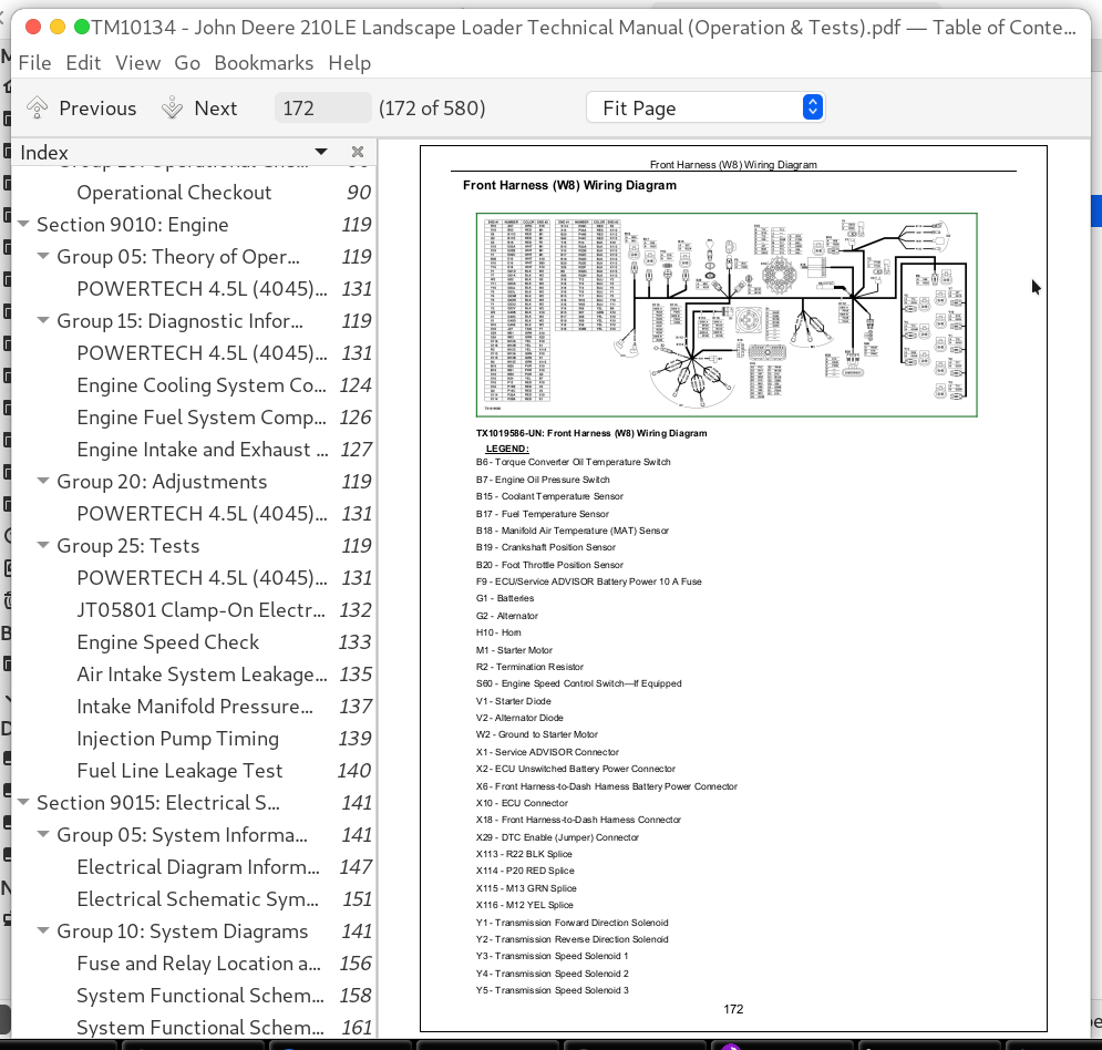
Front Harness (W8) Wiring Diagram
Fuse and Relay Location and Specifications
PTO Harness (W12) Wiring Diagram342200224If Equipped
Rear Harness (W10) Component Location
Rear Harness (W10) Wiring Diagram
System Functional Schematic and Section Legend
System Functional Schematic, Wiring Diagram, and Component Location Legend
15 - Sub-System Diagnostics
Charging Circuit Theory of Operation
Display Monitor and Indicators Circuit Theory of Operation
Engine Control Unit (ECU) Circuit Theory of Operation
Power Circuit Theory of Operation
PTO Circuit Theory of Operation342200224If Equipped
Starting Circuit Theory of Operation
Transmission Control and Park Brake Circuit Theory of Operation
20 - References
Alternator Test Procedure
Connector, CINCH342204242 Replace
Connector, DEUTSCH342204242 Rectangular or Triangular Replace
Connector, DEUTSCH342204242 Replace
Connector, (Pull Type) METRI-PACK342204242 Replace
Connector, (Push Type) METRI-PACK342204242 Replace
Connector, WEATHER PACK342204242 Replace
Contact, CINCH342204242 Install
Contact, DEUTSCH342204242 Install
Contact, WEATHER PACK342204242 Install
Electrical Circuit Component Checks
Electrical Component Specifications
Engine Coolant Temperature Sensor Test
Reading Diagnostic Trouble Codes (DTCs) Using Blink Method
Reading Diagnostic Trouble Codes (DTCs) Using Service ADVISOR342204242
Service ADVISOR342204242 Connection Procedure
Transmission Control Lever (TCL) Test
Transmission Solenoid Check
Wire Harness Test
9020 - POWER TRAIN
05 - Theory of Operation
Clutch and Mechanical Front Wheel Drive (MFWD) Operation
Clutch Modulation Operation
Differential Lock Operation
Differential Operation
MFWD Differential Operation342200224Equal Traction
MFWD Differential Operation342200224Unequal Traction
MICO Power Boost Brake Valve342200224Both Pedals Applied, Engine Off Position
MICO Power Boost Brake Valve342200224Both Pedals Applied Position
MICO Power Boost Brake Valve342200224Neutral Position
MICO Power Boost Brake Valve342200224One Pedal Applied Position
Park Brake Operation
Power Shift Power Train Overview
Power Shift Transmission Clutch Engagement And Solenoids Activated
Power Shift Transmission Gear Flow
Service Brake Operation
Torque Converter Operation
Transmission Filter Operation
Transmission Pump Operation
15 - Diagnostic Information
Diagnose Transmission Malfunctions
Differential Lock Slips or Chatters When Engaged
Differential Lock Will Not Release
Excessive Power Train Noise
Hydraulic Circuit342200224Symbols
Machine Lacks Power or Moves Slow
No Differential Lock Operation
No Power to Mechanical Front Wheel Drive (MFWD)
No Power to One Wheel of Mechanical Front Wheel Drive (MFWD)
Park Brake Piston Leak
Park Brake Will Not Hold
Park Brake Will Not Release
Poor Service Brakes
Power Train Component Location
Power Train Schematic-First Forward Mechanical Front Wheel Drive (MFWD) Engaged
Power Train Schematic-First Reverse
Power Train Schematic-Fourth Forward
Power Train Schematic-Neutral
Rear Axle Overfilled With Oil
Service Brakes Chatter or Noisy
Service Brakes Will Not Release
Transmission Overheats
Transmission Slippage
20 - Adjustments
Brake Pedal Adjustment
Brake System Bleeding Procedure
Park Brake Release for Towing
Steering Angle Check and Adjust342200224MFWD Axle
Toe-In Check and Adjust
Tracking Angle Check and Adjust
25 - Tests
Brake Valve Leakage Test
Clutch Pressure Test
Cooler In and Cooler Out Pressure Test
Differential Lock Pressure Test
Mechanical Front Wheel Drive (MFWD) Pressure Test
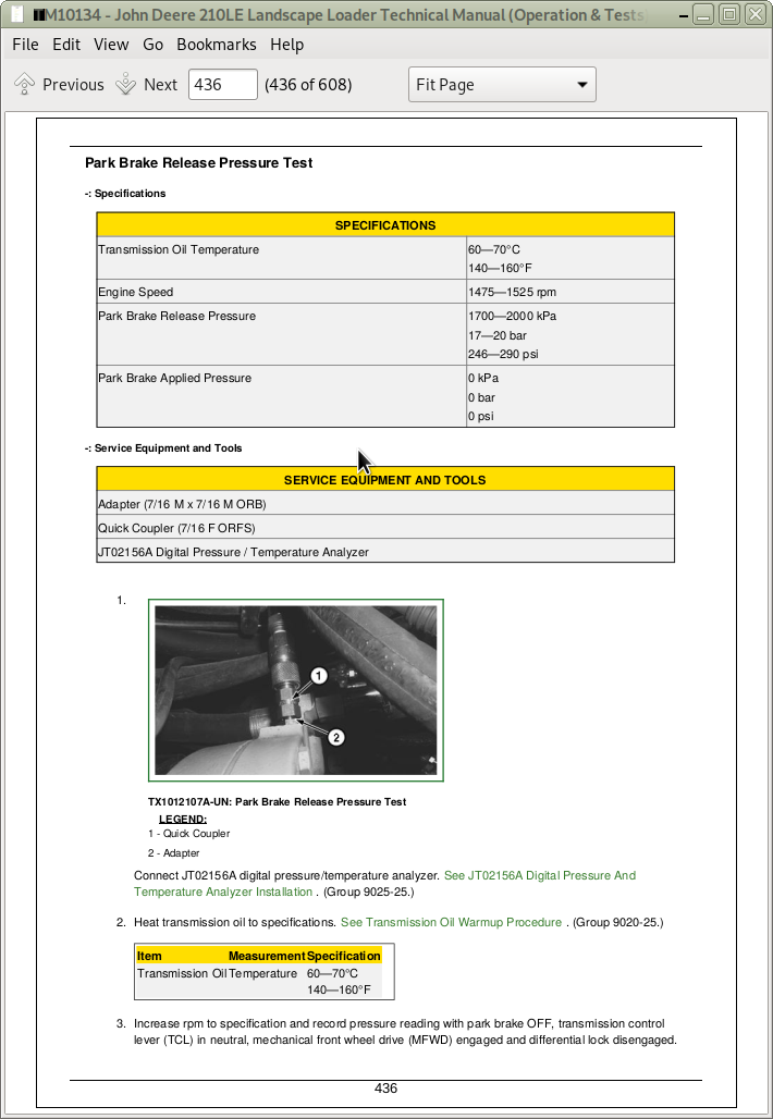
Park Brake Release Pressure Test
Power Shift Transmission Overall Test Connections, Ports, and Locations
Solenoid Circuit Leakage Test
Torque Converter-In Relief Valve Test
Torque Converter Stall Speed Test
Transmission Oil Warmup Procedure
Transmission Pump Flow Test
Transmission System Pressure Test
9025 - HYDRAULIC SYSTEM
05 - Theory of Operation
Control Valve342200224Boom Section342200224Float
Control Valve342200224Boom Section342200224Raise
Control Valve342200224Bucket Section342200224Dump
Control Valve342200224Flow Control Section
Control Valve342200224Hitch Lift Section342200224Raise
Control Valve342200224Hitch Pitch Section
Control Valve342200224Hitch Tilt and Auxiliary Sections
Control Valve342200224Inlet Section with System Relief Valve
Hydraulic Filter Operation
Hydraulic Pump Operation
Open-Center Hydraulic System
Priority Valve Section Operation342200224Steering Actuated
Relief Valve Operation With Anticavitation
Relief Valve Without Anticavitation
Steering Valve Operation
15 - Diagnostic Information
Control Valve Sticks or Works Hard
Engine Pulls Down Excessively During Control Valve Operation
Excessive Pump Noise
Foaming Oil
Functions Drift
Hydraulic Control Valve Component Locations
Hydraulic Function Makes Chattering Noise
Hydraulic Oil Overheats
Hydraulic Pump Leaking
Hydraulic System Component Location
Hydraulic System Schematic
Loader or Hitch Operates Slowly in One Function
Low Hydraulic Power (Low Hydraulic Pressure)
Machine Turns in Opposite Direction
Machine Turns when Steering Valve is in Neutral
No Loader and Hitch Hydraulics (Steering OK)
No Loader, Hitch, or Steering Hydraulics
No Loader or Hitch Power in One Function
No or Slow Hitch Hydraulics (Loader Hydraulics OK)
No Response when Steering Wheel Is Turned
No Steering Hydraulics (Control Valve and Hitch Hydraulics OK)
Slow Hydraulic Functions
Slow Loader and Hitch Hydraulics (Low Pump Output)
Slow Steering Hydraulics
Steering Valve Does Not Return to Neutral
Steering Wheel Kickback
20 - Adjustments
Loader Bucket Self-Leveling Linkage Indicator Adjustment
Return-to-Dig Switch Adjustment
25 - Tests
Circuit Relief Valve Test342200224With Remote Pump
Function Drift Test
Hydraulic Cylinder Leakage Test
Hydraulic Oil Cooler Restriction Test
Hydraulic Oil Warmup Procedure
Hydraulic Pump Flow Test
JT02156A Digital Pressure And Temperature Analyzer Installation
Steering Cylinder Leakage Test
Steering Load Sense Relief Valve Pressure Test
Steering System Leakage Test
System Relief Valve Pressure Test
9026 - HYDROSTATIC SYSTEM
05 - Theory of Operation
Hydrostatic PTO High Pressure Relief Valve Operation
Hydrostatic PTO Motor Operation
Hydrostatic PTO Pump Control Circuit Operation342200224Actuated
Hydrostatic PTO Pump Operation
15 - Diagnostic Information
Excessive Noise from PTO System (Under Load or No Load)
Hydraulic Oil Overheats During PTO Operation
Hydrostatic PTO System Component Location
Hydrostatic PTO System Schematic
PTO Does Not Go To or Stay in Neutral
PTO Does Not Operate
PTO Lacks Power or Is Sluggish
PTO Operates Erratically
PTO Rotates in Wrong Direction
20 - Adjustments
Hydrostatic PTO Pump Servo Piston Neutral Adjustment
25 - Tests
Hydrostatic PTO Pump High Pressure Relief Valve and Pressure Override Valve Tests and Adjustments
Hydrostatic PTO Pump Neutral Charge Relief Valve Pressure Test and Adjustment
PTO Oil Cooler Restriction Test
John Deere 210LE Landscape Loader Operation & Test Technical Manual (TM10134)


