John Deere 310K Backhoe Loader Operation & Test Technical Manual (TM12447)
Catalog:
Model:
Complete technical Operation & Test Manual with electrical wiring diagrams for John Deere 310K Backhoe Loader. It's the same service manual used by dealers that guaranteed to be fully functional and intact without any missing page.
John Deere 310K Backhoe Loader Operation & Test Technical Manual (including maintenance, overhaul, disassembling & assembling, adjustment, tune-up, operation, inspecting, diagnostic & troubleshooting…) is divided into different sections. Each section covers a specific component or system with detailed illustrations. A table of contents is placed at the beginning of each section. Pages are easily found by category, and each page is expandable for great detail. The printer-ready PDF documents work like a charm on all kinds of devices.
TM12447 - John Deere 310K Backhoe Loader Operation and Test Technical Manual.pdf
Covered models: 310K (PIN:1T0310KX**D219707-; 1T0310KX**C219607-)
MAIN SECTIONS
Foreword
Manual Identification-READ THIS FIRST!
General Information
Safety
Diagnostics
Engine Control Unit (ECU) Diagnostic Trouble Codes
Engagement and Monitor Unit (EMU) Diagnostic Trouble Codes
Transmission Control Unit (TCU) Diagnostic Trouble Codes
Vehicle Control Unit (VCU) Diagnostic Trouble Codes
Operational Checkout Procedure
Operational Checkout Procedure
Engine
Theory of Operation
Diagnostic Information
Adjustments
Tests
Electrical System
System Information
System Diagrams
Sub-System Diagnostics
Monitor Operation
References
Power Train
Theory of Operation
Diagnostic Information
Adjustments
Tests
Hydraulic System
Theory of Operation
Diagnostic Information
Adjustments
Tests
Heating and Air Conditioning
Theory of Operation
Diagnostic Information
Tests
tm12447 - 310K Backhoe Loader
Table of Contents
Foreword
Manual Identification—READ THIS FIRST!
Section 9000: General Information
Group 01: Safety
Recognize Safety Information
Follow Safety Instructions
Operate Only If Qualified
Wear Protective Equipment
Avoid Unauthorized Machine Modifications
Inspect Machine
Stay Clear of Moving Parts
Avoid High-Pressure Oils
Avoid High-Pressure Fluids
Work In Ventilated Area
Prevent Fires
Prevent Battery Explosions
Handle Chemical Products Safely
Decommissioning — Proper Recycling and Disposal of Fluids and Components
Prepare for Emergencies
Use Steps and Handholds Correctly
Start Only From Operator's Seat
Use and Maintain Seat Belt
Prevent Unintended Machine Movement
Prevent Unintended Machine Movement—If Equipped With Pilot Controls
Avoid Work Site Hazards
Keep Riders Off Machine
Avoid Backover Accidents
Avoid Machine Tipover
Add and Operate Attachments Safely
Use Special Care When Operating
Operating or Traveling On Public Roads
Inspect and Maintain ROPS
Park and Prepare for Service Safely
Service Cooling System Safely
Remove Paint Before Welding or Heating
Make Welding Repairs Safely
Drive Metal Pins Safely
Service Tires Safely
Section 9001: Diagnostics
Group 10: Engine Control Unit (ECU) Diagnostic Trouble Codes
Engine Control Unit (ECU) Diagnostic Trouble Codes
000029.03 - Hand Throttle
000029.04 - Hand Throttle
000029.14 - Hand Throttle
000091.03 - Foot Throttle
000091.04 - Foot Throttle
000091.14 - Foot Throttle
000107.00 - Engine Air Filter
000190.00 - Engine Speed
000190.16 - Engine Speed
000237.31 - Vehicle ID Number
000628.12 - Memory Error
001075.05 - Fuel Pump Control
001075.06 - Fuel Pump Control
001321.05 - Starter Relay
001321.06 - Starter Relay
001321.16 - Starter Relay
002003.09 - No CAN From TCU
002047.09 - Can Communication Lost with VCU
002071.09 - No CAN From VCU
523702.09 - Flex Power Message Missing
Group 20: Engagement and Monitor Unit (EMU) Diagnostic Trouble Codes
Engagement and Monitor Unit (EMU) Diagnostic Trouble Codes
000096.03 - Fuel Level Sensor
000096.04 - Fuel Level Sensor
000168.03 - Battery Voltage
000168.04 - Battery Voltage
000234.02 - Software Incorrect
000237.02 - VIN Mismatch
000237.13 - VIN Mismatch
000237.31 - VIN Missing
000628.12 - Memory Error
000629.12 - Controller Fault
000920.06 - Alarm Output
000920.12 - Alarm Output
001196.11 - Antitheft
002000.09 - No CAN from ECU
002003.09 - No CAN from TCU
002071.09 - No CAN from VCU
002251.09 - No CAN from MTG
524082.07 - Display Buttons
Group 30: Transmission Control Unit (TCU) Diagnostic Trouble Codes
Transmission Control Unit (TCU) Diagnostic Trouble Codes
000070.04 - Park Brake
000070.07 - Park Brake
000070.14 - Park Brake
000177.00 - Trans Oil Temp
000177.04 - Trans Oil Temp
000525.02 - Requested Gear
000525.03 - Requested Gear
000525.04 - Requested Gear
000525.05 - Requested Gear
000604.04 - TCL Neutral SW
000617.07 - Park Brake Circuit
000618.07 - Park Brake Circuit
000629.12 - Controller Fault
000736.03 - Y3 Solenoid
000736.05 - Y3 Solenoid
000736.06 - Y3 Solenoid
000737.03 - Y4 Solenoid
000737.05 - Y4 Solenoid
000737.06 - Y4 Solenoid
000738.03 - Y5 Solenoid
000738.05 - Y5 Solenoid
000738.06 - Y5 Solenoid
000746.03 - Differential Lock
000746.05 - Differential Lock
000746.06 - Differential Lock
000746.31 - Differential Lock
000767.05 - TCL Reverse SW
000880.06 - Brake Lights
000903.05 - TCL Forward SW
001045.04 - Brake Light SW
002000.09 - No CAN from ECU
002023.09 - No CAN from PDU
002034.09 - No CAN from AVC
002071.09 - No CAN from TCU
002612.05 - MFWD Solenoid
002612.06 - MFWD Solenoid
004312.02 - TCL Selector
004312.03 - TCL Selector
004312.05 - TCL Selector
004312.06 - TCL Direction Driver
522379.03 - Park Brake
522379.04 - Park Brake
522379.05 - Park Brake
522379.06 - Park Brake
522405.03 - PB Pressure Switch
523689.04 - Diff Lock Switch
523689.07 - Diff Lock Switc
523702.07 - Flexpower
523702.08 - Flexpower
523702.09 - Flexpower
523702.10 - Flexpower
524172.03 - Clutch Disconnect
524172.04 - Clutch Disconnect
524172.09 - Clutch Disconnect
Group 40: Vehicle Control Unit (VCU) Diagnostic Trouble Codes
Vehicle Control Unit (VCU) Diagnostic Trouble Codes
000237.02 - VIN Mismatch
000237.13 - VIN Mismatch
000237.31 - VIN Missing
000628.12 - Memory Error
001713.00 - Hyd Oil Restriction
520688.05 - Pilot Enable Driver
520688.06 - Pilot Enable Driver
520713.03 - Seat Position
520713.04 - Seat Position
520713.07 - Seat Position
520713.12 - Seat Position
520713.13 - Seat Position
Section 9005: Operational Checkout Procedure
Group 10: Operational Checkout Procedure
Operational Checkout Procedure
Section 9010: Engine
Group 05: Theory of Operation
John Deere Engine Operation
Engine Cooling System Operation
Cold Start Aid System Operation
Group 15: Diagnostic Information
John Deere Engine Operation
Engine Identification
Engine Cooling System Component Location
Engine Fuel System Component Location
Engine Intake and Exhaust Component Location
Group 20: Adjustments
John Deere Engine Operation
Group 25: Tests
John Deere Engine Operation
Fluid Sampling Procedure—If Equipped
Engine Speed Check
Air in Fuel Test
Engine Thermostat Test
Thermal Bypass Valve Test
Intake Manifold Pressure—Turbocharger Boost
Section 9015: Electrical System
Group 05: System Information
Electrical Diagram Information
Electrical Schematic Symbols
Group 10: System Diagrams
Fuse and Relay Location and Specifications
System Functional Schematic, Wiring Diagram, and Component Location Legend
System Functional Schematic and Section Legend
Glow Plug Harness (W9) Component Location
Glow Plug Harness (W9) Wiring Diagram
Engine Harness (W10) Component Location
Engine Harness (W10) Wiring Diagram
Transmission Harness (W13) Component Location
Transmission Harness (W13) Wiring Diagram
Cab Harness (W14) Component Location
Cab Harness (W14) Wiring Diagram
Canopy Harness (W15) Component Location
Canopy Harness (W15) Wiring Diagram
Canopy (With Windshield) Harness (W16) Component Location
Canopy (With Windshield) Harness (W16) Wiring Diagram
Roof Harness (W17) Component Location
Roof Harness (W17) Wiring Diagram
Radio Harness (W18) Component Location
Radio Harness (W18) Wiring Diagram
Heater and Air Conditioner Harness (W19) Component Location
Heater and Air Conditioner Harness (W19) Wiring Diagram
Pilot Control, Selective Flow and Ride Control Harness (W20) Component Location
Pilot Control, Selective Flow and Ride Control Harness (W20) Wiring Diagram
Selective Flow and Ride Control Harness (W21) Component Location
Selective Flow and Ride Control Harness (W21) Wiring Diagram
Fuel Lift Pump Relay Harness (W22) Component Location
Fuel Lift Pump Relay Harness (W22) Wiring Diagram
Loader Auxiliary Control Harness (W23) Component Location—If Equipped
Loader Auxiliary Control Harness (W23) Wiring Diagram—If Equipped
Start Aid Switch Harness (W24) Component Location
Start Aid Switch Harness (W24) Wiring Diagram
Loader Coupler Console Harness (W25) Component Location
Loader Coupler Console Harness (W25) Wiring Diagram
Loader Coupler Solenoid Harness (W26) Component Location
Loader Coupler Solenoid Harness (W26) Wiring Diagram
Ride Control Solenoid Harness (W27) Component Location
Ride Control Solenoid Harness (W27) Wiring Diagram
Selective Flow Solenoid Harness (W28) Component Location
Selective Flow Solenoid Harness (W28) Wiring Diagram
Loader Auxiliary Solenoid Harness (W29) Component Location
Loader Auxiliary Solenoid Harness (W29) Wiring Diagram
Pilot Enable Pattern Select Valve Harness (W30) Component Location
Pilot Enable Pattern Select Valve Harness (W30) Wiring Diagram
Pilot Enable Switch Harness (W31) Component Location
Pilot Enable Switch Harness (W31) Wiring Diagram
Return-to-Dig Harness (W32) Component Location
Return-to-Dig Harness (W32) Wiring Diagram
Air Conditioner Compressor Clutch Harness (W39) Component Location
Air Conditioner Compressor Clutch Harness (W39) Wiring Diagram
Blower Mode Door Motor Harness (W40) Component Location
Blower Mode Door Motor Harness (W40) Wiring Diagram
Fuel Lift Pump Jumper Harness (W45) Component Location—Engine 4045HT085
Fuel Lift Pump Jumper Harness (W45) Wiring Diagram—Engine 4045HT085
Modular Telematics Gateway (MTG) Harness (W6002) Component Location
Modular Telematics Gateway (MTG) Harness (W6002) Wiring Diagram
Satellite (SAT) Harness (W6003) Component Location
Satellite (SAT) Harness (W6003) Wiring Diagram
Group 15: Sub-System Diagnostics
Start and Charge Circuit Theory of Operation
Controller Area Network (CAN) Circuit Theory of Operation
Engine Control Unit (ECU) Circuit Theory of Operation
Engagement and Monitor Unit (EMU) Circuit Theory of Operation
Transmission Control Circuit Theory of Operation
Loader Auxiliary Control Unit Circuit Theory of Operation
JDLink™ Circuit Theory of Operation
Group 16: Monitor Operation
Engagement and Monitor Unit (EMU)—Service Menu
Engagement and Monitor Unit (EMU)—Clear Codes
Engagement and Monitor Unit (EMU)—Diagnostics
Engagement and Monitor Unit (EMU)—Main Menu Visible or Hidden
Engagement and Monitor Unit (EMU)—Restore Monitor Defaults
Engagement and Monitor Unit (EMU)—Machine Options
Engagement and Monitor Unit (EMU)—Setting Hour Meter
Security System Enable - Disable
Security System Configuration
Security System Operation
Group 20: References
Electrical Component Specifications
Service ADVISOR™ Connection Procedure
JDLink™ Connection Procedure
Reading Diagnostic Trouble Codes (DTCs)
Diagnostic Trouble Code (DTC) Monitor Messages
Intermittent Diagnostic Trouble Code (DTC) Diagnostics
Controller Area Network (CAN) Circuit Test
Controller Area Network (CAN) Resistor Test
Alternator Test
Wire Harness Test
Sensor Circuit Test
Crank Position Sensor Test
Transmission Control Circuit Test
Transmission Solenoid Circuit Test
Transmission Control Lever (TCL) Test
Transmission Solenoid Check
Throttle Position Sensor Test
Engine Speed Control Pedal Test
Vehicle Control Unit (VCU) Output Test
Seat Position Sensor Remove and Install
Controller Remove and Install
Section 9020: Power Train
Group 05: Theory of Operation
Power Train Overview
Transmission Pump Operation
Torque Converter Operation
Transmission Filter Operation
Clutch Modulation Operation
Clutch Pack Operation
Transmission Gear Flow
Transmission Clutch Engagement and Solenoid Activation
Differential Operation
Differential Lock Operation
Mechanical Front Wheel Drive (MFWD) Operation—If Equipped
Mechanical Front Wheel Drive (MFWD) Differential Operation—If Equipped
Park Brake Operation
Service Brake Operation
Power Boost Service Brake Valve Operation
Group 15: Diagnostic Information
Hydraulic Circuit—Symbols
Power Train Component Location
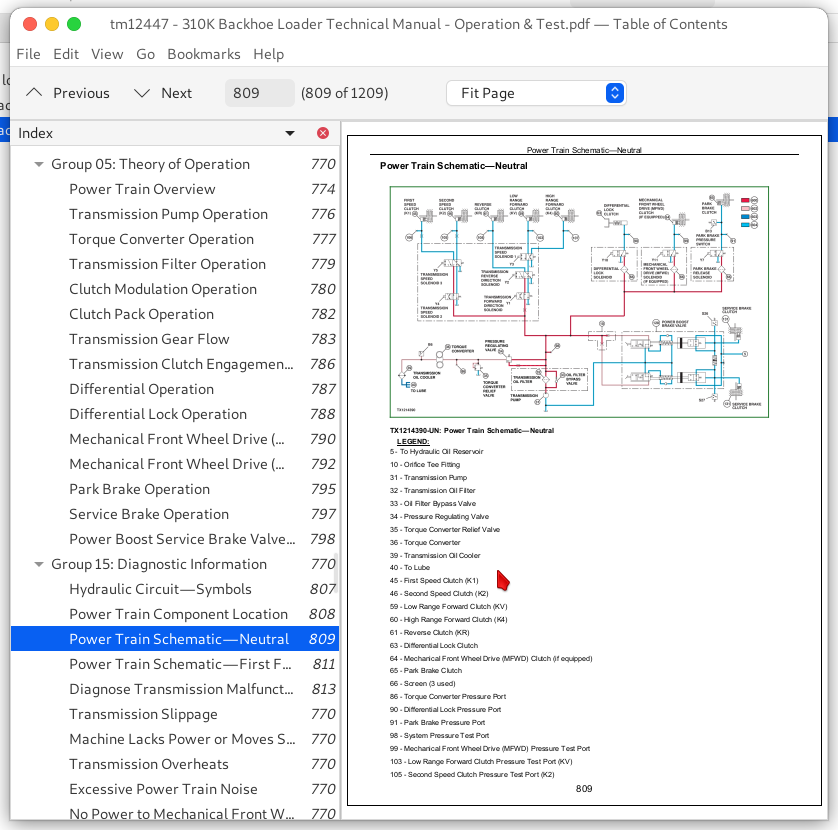
Power Train Schematic—Neutral
Power Train Schematic—First Forward
Diagnose Transmission Malfunctions
Transmission Slippage
Machine Lacks Power or Moves Slow
Transmission Overheats
Excessive Power Train Noise
No Power to Mechanical Front Wheel Drive (MFWD)
No Power to One Wheel of Mechanical Front Wheel Drive (MFWD)
No Differential Lock Operation
Differential Lock Slips or Chatters When Engaged
Differential Lock Will Not Release
Rear Axle Overfilled With Oil
Poor Service Brakes
Brake Pedal Hard to Push
Service Brakes Will Not Release
Service Brakes Chatter or Noisy
Park Brake Will Not Hold
Park Brake Will Not Release
Group 20: Adjustments
Mechanical Park Brake Release—Towing
Service Brake Pedal Adjustment
Service Brake Bleed Procedure
Tracking Angle Check and Adjust
Toe-In Check and Adjust
Steering Angle Check and Adjust
Group 25: Tests
Transmission Oil Warm-Up Procedure
Transmission Oil Sampling Procedure—If Equipped
Transmission Overall Test Connections, Ports, and Locations
Torque Converter Stall Speed Test
Torque Converter Inlet Pressure Test
Power Boost Service Brake Valve Leakage Test
Park Brake Release Pressure Test
Transmission System Pressure Test
Service Brake Boost Pressure Test
Clutch Pressure Test
Differential Lock Pressure Test
Mechanical Front Wheel Drive (MFWD) Pressure Test
Cooler In and Cooler Out Pressure Test
Solenoid Circuit Leakage Test
Transmission Pump Flow Test
Section 9025: Hydraulic System
Group 05: Theory of Operation
Hydraulic System Operation
Hydraulic Pump Operation
Hydraulic Filter Operation
Steering Valve Operation
Ride Control Operation—If Equipped
System Relief Valve Operation
Circuit Relief Valve without Anticavitation—Loader and Backhoe
Circuit Relief Valve with Anticavitation—Backhoe Swing, Boom Lower
Circuit Relief Valve with Anticavitation—Backhoe Bucket Curl and Loader Bucket Dump
Backhoe Control Valve Operation
Pilot Control Valve Operation—If Equipped
Pilot Enable and Pattern Select Valve Operation—If Equipped
Loader Auxiliary Control Operation—If Equipped
Loader and Stabilizer Control Valve Operation
Attachment Coupler Hydraulic Operation
Hydraulic Thumb Operation—If Equipped
Group 15: Diagnostic Information
Hydraulic System Schematic
Hydraulic System Component Location
Slow Steering Hydraulics
No Steering Hydraulics, Loader Hydraulics OK
Hard Steering, Loader Hydraulics OK
Steering Valve Does Not Return to Neutral
No Response When Steering Wheel is Turned, Loader Hydraulics OK
Machine Turns in Opposite Direction
Excessive Vibration of the Steering Wheel
Machine Turns When Steering Valve is in Neutral
Steering Wheel Kickback
Excessive Steering Wheel Turns to Steer Machine
Erratic (“Spongy”) Steering
Steering Wheel "Locks" Up
Poor Centering of Steering Wheel (Wheels Continue to Move After Steering Wheel is Stopped)
Steering Wheel or Front Wheels Slowly Turn by Themselves When Using Backhoe or Loader
Steering Wheel Turns Apply Rear Axle Service Brakes
Steering Wheel Turns Freely With No Resistance or Action On Steered Wheels
Steering Wheel Turns With Slight Resistance and No Action On Steered Wheels
Wander—Machine Will Not Stay in a Straight Line
No Loader or Steering Hydraulics
No Loader Hydraulics
Low Loader Hydraulic Power
Low Hydraulic Power
Engine Pulls Down Excessively During Loader Operation
Engine Pulls Down Excessively During Backhoe Operation
Slow Hydraulic Functions
Backhoe Operates Slowly in One Function
Loader Operates Slowly in One Function
No Backhoe Power in One Function
No Loader Power in One Function
No Stabilizer Hydraulics
Slow Loader and Backhoe Hydraulics
Low Hydraulic Power (Low Hydraulic Pressure)
Hydraulic Function Makes "Chattering" Noise
Functions Drift
Control Valve Sticks or Works Hard
Hydraulic Oil Overheats
Foaming Oil
Hydraulic Pump Leaking
Excessive Pump Noise
Attachment Coupler Not Working
Group 20: Adjustments
Backhoe Control Lever to Valve Linkage (Two Lever) Adjustment
Backhoe Control Lever to Valve Linkage (Four Lever) Adjustment—If Equipped
Auxiliary Selective Flow Control Valve Adjustment—If Equipped
Pilot Control Pressure Adjustment
Pilot Enable and Pattern Select Valve Accumulator Discharge Procedure
Loader Bucket Self-Leveling Linkage and Return-To-Dig Switch Adjustment
Loader and Stabilizer Lever Adjustment
Ride Control Accumulator Charge Procedure
Ride Control Accumulator Charge Check Procedure
Ride Control Accumulator Hydraulic Pressure Release Procedure
Group 25: Tests
JT02156A Digital Pressure and Temperature Analyzer Kit Installation
Hydraulic Oil Warm-Up Procedure
Hydraulic Oil Sampling Procedure—If Equipped
Hydraulic Circuit Pressure Release
Hydraulic Pump Flow Test
Backhoe Relief Valve Pressure Test
Loader Relief Valve Pressure Test
Pilot Control Pressure Test
Pilot Control Accumulator Charge Pressure Test
Hydraulic Oil Cooler Restriction Test
Circuit Relief Valve Test—With Remote Pump
Steering System Leakage Test
Steering Cylinder Leakage Test
Function Drift Test
Hydraulic Cylinder Leakage Test
Loader and Stabilizer Control Valve Lockout Leakage Test
Section 9031: Heating and Air Conditioning
Group 05: Theory of Operation
Air Conditioning System Cycle Of Operation
Group 15: Diagnostic Information
Air Conditioning and Heater System Component Location
Air Conditioning System Does Not Operate
Air Conditioner Does Not Cool Interior of Cab
Air Conditioner Runs Constantly, Too Cold
Heater System Does Not Operate
Heater Does Not Warm Interior of Cab
Interior Windows Continue to Fog
Group 25: Tests
Refrigerant Cautions and Proper Handling
R134a Refrigerant Cautions
R134a Oil Charge Capacity
R134a Refrigerant Charge Capacity
Air Conditioner and Heater Operational Checks
Air Conditioner Compressor Clutch Test
Air Conditioner High/Low Pressure Switch Test
Air Conditioner Freeze Control Switch Test
R134a Air Conditioning System Test
Operating Pressure Diagnostic Chart
Expansion Valve Test
Blower Motor Speed Switch Test
Blower Motor Resistor Test
Blower Motor Test
Air Conditioning Mode Switch Test
Air Conditioning System Leak Test
Refrigerant Hoses and Tubing Inspection
EXCERPT:
TM12447 - 310K Backhoe Loader
Cold Start Aid System Operation
Auto-Ether Injection (If Equipped)—Engines 4045HT054, 4045HT086, 4045TT096
TX1102769-UN: Auto-Ether Injection System
LEGEND:
1 - Intake Manifold
2 - Ether Canister
Y15 - Start Aid Solenoid
Machines with engines 4045HT054, 4045HT086, and 4045TT096 may use an optional auto-ether injection cold weather starting aid. Ether injection helps to start the engine in cold weather by injecting a specific amount of ether into the intake manifold (1).
When the ignition is ON and the engine control unit (ECU) detects the fuel temperature is below a specified temperature, the start aid solenoid (Y15) energizes, and ether flows from the canister (2) to the intake manifold (1) and mixes with intake air. For more information on the electrical control of auto-ether injection, see Start and Charge Circuit Theory of Operation .
(Group 9015-15.)
When the ether/air mixture reaches the combustion chamber, it mixes with diesel fuel. Ether ignites at a lower temperature than diesel fuel, therefore, inside the combustion chamber the ether ignites first, heating the diesel fuel and aiding combustion.
Glow Plugs—Engine 4045HT085
...
John Deere 310K Backhoe Loader Operation & Test Service Manual (TM12447)


