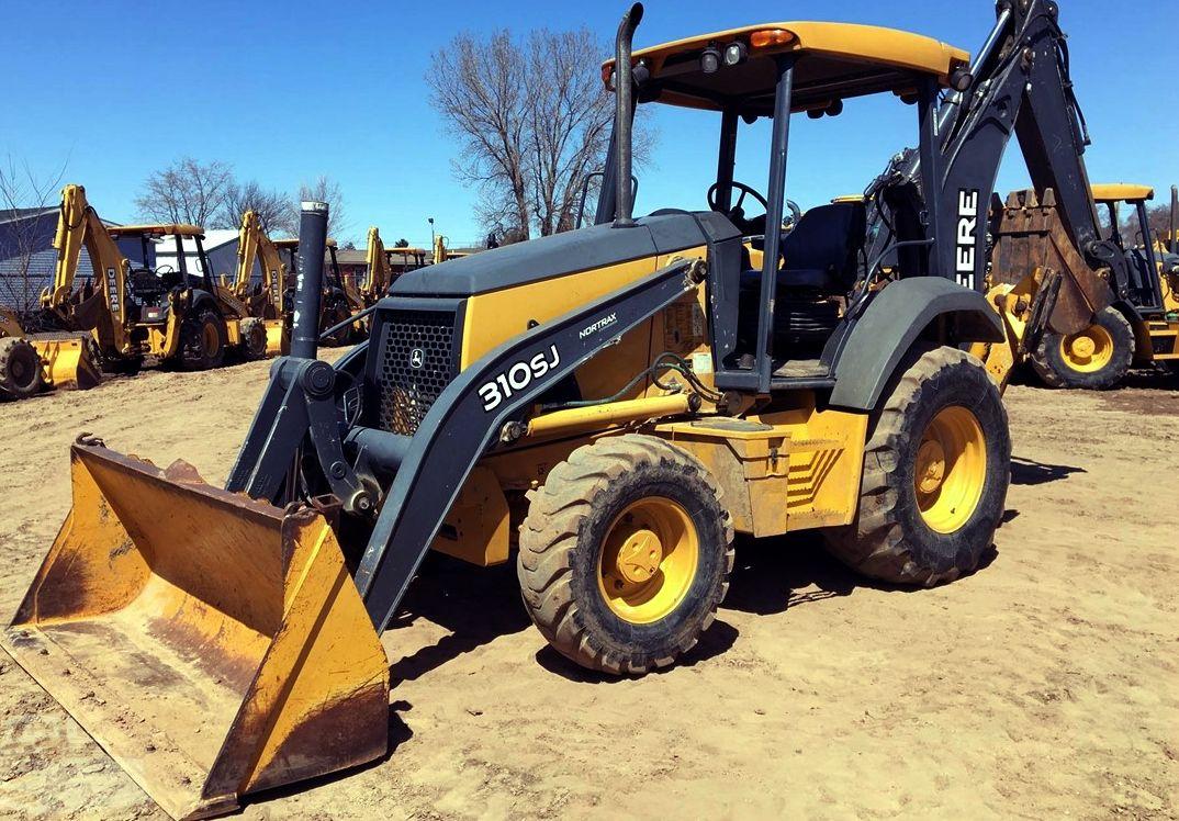
John Deere 310SJ Backhoe Loader Repair Technical Manual (TM10849)
Catalog:
Model:
Complete Repair Technical Manual for John Deere 310SJ Backhoe Loader. It's the same service manual used by dealers that guaranteed to be fully functional and intact without any missing page.
John Deere 310SJ Backhoe Loader Repair Technical Manual (including maintenance, overhaul, disassembling & assembling, adjustment, tune-up, operation, inspecting, diagnostic & troubleshooting…) is divided into different sections. Each section covers a specific component or system with detailed illustrations. A table of contents is placed at the beginning of each section. Pages are easily found by category, and each page is expandable for great detail. The printer-ready PDF documents work like a charm on all kinds of devices.
TM10849 - John Deere 310SJ Backhoe Loader (S.N. 159760-) Repair Technical Manual.pdf
820 pages, bookmarked, Searchable, Printable, high quality PDF
EXCERPT:
TM10849 - 310SJ Backhoe Loader (S.N. 159760— )
Make Welding Repairs Safely
T133547-UN: Avoid Heating Near Pressurized Fluid Lines
IMPORTANT:
Disable electrical power before welding. Turn off main battery switch or disconnect positive battery cable.
Separate harness connectors to engine and vehicle microprocessors.
Avoid welding or heating near pressurized fluid lines. Flammable spray may result and cause severe burns if pressurized lines fail as a result of heating. Do not let heat go beyond work area to nearby pressurized lines.
Remove paint properly. Do not inhale paint dust or fumes. Use a qualified welding technician for structural repairs. Make sure there is good ventilation. Wear eye protection and protective equipment when welding.
...
TABLE OF CONTENTS................1
Section 00: General Information................15
Group 0001: Safety Information................15
Recognize Safety Information................18
Follow Safety Instructions................19
Operate Only If Qualified................20
Wear Protective Equipment................21
Avoid Unauthorized Machine Modifications................22
Inspect Machine................23
Stay Clear of Moving Parts................24
Avoid High-Pressure Oils................25
Avoid High-Pressure Fluids................26
Beware of Exhaust Fumes................27
Prevent Fires................28
Prevent Battery Explosions................29
Handle Chemical Products Safely................30
Dispose of Waste Properly................31
Prepare for Emergencies................32
Use Steps and Handholds Correctly................33
Start Only From Operator's Seat................34
Use and Maintain Seat Belt................35
Prevent Unintended Machine Movement................36
Prevent Unintended Machine Movement—If Equipped With Pilot Controls................37
Avoid Work Site Hazards................38
Keep Riders Off Machine................40
Avoid Backover Accidents................41
Avoid Machine Tipover................42
Add and Operate Attachments Safely................43
Use Special Care When Operating................44
Operating or Traveling On Public Roads................45
Inspect and Maintain ROPS................46
Prevent Unintended Detonation of Explosive Devices................47
Park and Prepare for Service Safely................48
Service Cooling System Safely................49
Remove Paint Before Welding or Heating................50
Make Welding Repairs Safely................51
Drive Metal Pins Safely................52
Service Tires Safely................53
Group 0003: Torque Values................16
Metric Bolt and Cap Screw Torque Values................56
Additional Metric Cap Screw Torque Values................58
Unified Inch Bolt and Cap Screw Torque Values................60
Service Recommendations for 37° Flare and 30° Cone Seat Connectors................62
Service Recommendations for O-Ring Boss Fittings................64
O-Ring Boss Fittings In Aluminum Housing Service Recommendations—Excavators................66
Service Recommendations for Flared Connections—Straight or Tapered Threads................69
Service Recommendations For Flat Face O-Ring Seal Fittings................71
O-Ring Face Seal Fittings With SAE Inch Hex Nut And Stud End For High Pressure Service Recommendations................73
O-Ring Face Seal Fittings With Metric Hex Nut And Stud End For Standard Pressure Service Recommendations................75
O-Ring Face Seal Fittings With Metric Hex Nut And Stud End For High Pressure Service Recommendations................78
Service Recommendations for Metric Series Four Bolt Flange Fitting................81
Service Recommendations For Inch Series Four Bolt Flange Fittings................83
Inch Series Four Bolt Flange Fitting For High Pressure Service Recommendations................85
Service Recommendations For Non-Restricted Banjo (Adjustable) Fittings................87
Service Recommendations For O-Ring Boss Fittings With Shoulder................90
Metric 24° O-Ring Seal DIN 20078 Service Recommendations................93
Section 01: Wheels................97
Group 0110: Powered or Non-Powered Wheels and Fastenings................97
Rear Wheel Assembly Remove and Install................100
Front Wheel Assembly Remove and Install................102
Tire Remove and Install................104
Section 02: Axles and Suspension Systems................107
Group 0225: Input Drive Shafts and U-Joints................107
Universal Joint and Drive Shaft Remove and Install................113
Group 0230: Non-Powered Wheel Axles................107
Hub Assembly Remove and Install................120
Spindle Assembly Remove and Install................122
Tie Rod Remove and Install................126
Non-Powered Front Axle Remove and Install................128
Group 0240: Powered Wheel Axle (MFWD)................107
Mechanical Front Wheel Drive (MFWD) Axle Remove and Install................134
Mechanical Front Wheel Drive (MFWD) Axle Disassemble................137
Mechanical Front Wheel Drive (MFWD) Axle Assemble................155
Open Differential Disassemble and Assemble—If Equipped................187
Limited Slip Differential Disassemble and Assemble—If Equipped................193
Group 0250: Axle Shaft, Bearings, and Reduction Gears................107
Service Brakes Inspection................205
Rear Axle Remove and Install................207
Rear Axle Disassemble................210
Park Brake Disassemble and Assemble................227
Rear Axle Assemble................245
Gear Tooth Contact Pattern Check................269
Section 03: Transmission................270
Group 0300: Removal and Installation................270
Transmission Remove................281
Transmission Install................291
Group 0315: Controls Linkage................270
Transmission Control Lever (TCL) Remove and Install................300
Group 0350: Gears, Shafts, and Power Shift Clutches................270
Remove Outer Components to Disassemble Transmission................307
Torque Converter Side of Transmission Case Disassemble................312
Clutch Packs Remove................316
High Range Forward, Low Range Forward, and Reverse Clutch Packs Disassemble and Assemble................322
First Speed and Third Speed Clutch Disassemble and Assemble................342
Second Speed Clutch Disassemble and Assemble................360
Mechanical Front Wheel Drive (MFWD) Clutch Disassemble and Assemble................378
Pump Drive Shaft Install................391
Clutch Packs Install................393
Torque Converter Side of Transmission Case Assemble................399
Install Outer Components to Assemble Transmission................406
Group 0360: Hydraulic System................270
Transmission Charge Pump Remove and Install................415
Transmission Charge Pump Disassemble and Assemble................419
Section 04: Engine................421
Group 0400: Removal and Installation................421
PowerTech and PowerTech E 4.5 L and 6.8 L John Deere Engines................423
Engine Remove................424
Engine Install................439
PowerTech and PowerTech E 4.5 L and 6.8 L John Deere Engines—Stage II or Tier 2 Engines................451
Engine Remove—Stage II or Tier 2 Engine................452
Engine Install—Stage II or Tier 2 Engine................461
Section 05: Engine Auxiliary Systems................468
Group 0505: Cold Weather Starting Aid................468
Coolant Heater Remove and Install................472
Starting Aid Nozzle Remove and Install................475
Starting Aid Nozzle Remove and Install—Stage II or Tier 2 Engine................477
Starting Aid Solenoid Remove and Install................479
Group 0510: Cooling System................468
Fan Remove and Install................483
Fan Belt Remove and Install................485
Radiator Remove and Install................487
Fan Remove and Install—Stage II or Tier 2 Engine................493
Fan Belt Remove and Install—Stage II or Tier 2 Engine................496
Radiator Remove and Install—Stage II or Tier 2 Engine................499
Group 0515: Speed Controls................468
Engine Speed Control Pedal Remove and Install................508
Group 0520: Intake System................468
Air Cleaner Remove and Install................512
Air Cleaner Remove and Install—Stage II or Tier 2 Engine................514
Charge Air Cooler Remove and Install................516
Group 0530: Exhaust System................468
Muffler With Turbocharger Remove and Install................521
Muffler With Turbocharger Remove and Install—Stage II or Tier 2 Engine................523
Group 0560: External Fuel Supply System................468
Fuel Tank Remove and Install................528
Auxiliary Water Separator Fuel Filter Remove and Install—If Equipped................531
Section 06: Torque Converter................533
Group 0651: Turbine, Gears and Shaft................533
Torque Converter Remove and Install................535
Torque Converter Disassemble and Assemble................536
Section 09: Steering System................537
Group 0960: Hydraulic System................537
Steering Column Remove and Install................543
Standard Steering Wheel and Column Disassemble and Assemble................548
Tilt Steering Wheel and Column Disassemble and Assemble................550
Steering Valve Remove and Install................552
Steering Valve Disassemble and Assemble................560
Non-Powered Front Axle Steering Cylinder Repair................566
Mechanical Front Wheel Drive (MFWD) Axle Steering Cylinder Disassemble and Assemble................571
Section 10: Service Brakes................577
Group 1011: Active Elements................577
Service Brake External Inspection................579
Brake Disk and Pressure Plate Remove and Install................580
Group 1060: Hydraulic System................577
Brake Valve Remove and Install................587
Brake Valve Disassemble and Assemble................593
Brake Valve Lines Disassemble and Assemble................600
Brake Pedals Remove and Install................602
Brake Pedal Adjustment................604
Brake Bleeding Procedure................606
Section 11: Park Brake................610
Group 1111: Active Elements................610
Park Brake Remove and Install................612
Section 17: Frame or Supporting Structure................613
Group 1740: Frame Installation................613
Welding Repair of Major Structures................615
RIVNUT RIVNUT is a registered trademark of The BF Goodrich Co. (KREMNUT) Fasteners Remove and Install................613
Main Frame Bushings Remove and Install................619
Group 1749: Chassis Weights................613
Counterweight Remove and Install................622
Section 18: Operator’s Station................624
Group 1800: Removal and Installation................624
Cab/ROPS Remove and Install................645
Group 1810: Operator Enclosure................624
Front Window Wiper and Wiper Motor Remove and Install................667
Rear Window Wiper and Wiper Motor Remove and Install................670
Front Cab Windowpane Remove and Install................673
Fixed Windowpanes Remove and Install................675
Cab Door and Side Window Disassemble and Assemble................676
Cab Door Hinges and Latch Adjustment................679
Upper Cab Door and Side Windowpanes Adjustment................681
Upper Cab Door and Side Window Latch Adjustment................683
Rear Window and Frame Assembly Remove and Install................684
Rear Windows Remove and Install................687
Headliner Remove and Install................690
Cab Roof Remove and Install................691
Group 1821: Seat and Seat Belt................624
Seat Assembly Remove and Install................695
Seat and Arm Rest Disassemble and Assemble................697
Seat Belt Disassemble and Assemble................699
Seat Slide, Lumbar Support, and Adjuster Control Levers Disassemble and Assemble................701
Seat Swivel and Swivel Latch Disassemble and Assemble................703
Seat Suspension and Shock Absorber Disassemble and Assemble................705
Air Suspension Seat Disassemble and Assemble—If Equipped................707
Group 1830: Heating and Air Conditioning................624
Proper Refrigerant Handling................718
R134a Refrigerant—Cautions................719
R134a Refrigerant Theory Of Operation................720
Refrigerant Hoses and Tubing Inspection................722
Air Conditioner Compressor Remove and Install................723
R134a Compressor Oil Check................725
R134a Compressor Oil Removal Procedure................727
R134a Component Oil Charge Procedure................728
Compressor Clutch Disassemble and Assemble................730
Clutch Hub Clearance Check................732
Compressor Manifold Inspect................733
Air Conditioning Compressor Disassemble and Assemble................734
R134a Refrigerant Recover, Recycle, and Charge Station Installation Procedure................738
R134a System Recover Procedure................740
R134a System Evacuate Procedure................742
R134a System Charge Procedure................746
R134a System Cleaning Procedure................748
R134a System Leak Testing................749
Heater Core Remove and Install................750
Evaporator Remove and Install................755
R134a System Flush Procedure................761
R134a System Purge Procedure................765
Air Conditioning Freeze Switch Remove and Install................766
Heater/Blower Assembly with Air Conditioning and Pressurizer System Disassemble and Assemble................770
Air Ducts Disassemble and Assemble................774
Condenser Disassemble and Assemble................776
Receiver Dryer Remove and Install................779
Expansion Valve—Remove and Install................782
Section 19: Sheet Metal and Styling................783
Group 1910: Hood and Engine Enclosure................783
Hood and Engine Enclosure Disassemble and Assemble................787
Group 1913: Miscellaneous Shields................783
Battery Box Disassemble and Assemble................792
Group 1921: Grille and Grille Housing................783
Grille and Grille Housing Disassemble and Assemble................796
Group 1927: Fenders................783
Fenders and Cab Skirts Remove and Install—If Equipped................799
Section 20: Safety, Convenience and Miscellaneous................800
Group 2001: Radio................800
Radio and Speakers Remove and Install................803
Antenna Remove and Install................805
Radio Speakers and Antenna Remove and Install................806
Group 2004: Horn and Warning Devices................800
Horn Remove and Install................808
Backup Alarm Remove and Install................809
Backup Alarm Volume Adjustment................810
Section 21: Main Hydraulic System................811
Group 2160: Hydraulic System................811
Hydraulic Pump Remove and Install................815
Hydraulic Pump Disassemble and Assemble................818
Hydraulic Filter Assembly Remove and Install................824
Hydraulic Reservoir Remove and Install................827
Hydraulic Reservoir Disassemble and Assemble................834
Hydraulic and Transmission Oil Coolers Remove and Install................836
Section 31: Loader................843
Group 3100: Loader................843
Loader Boom Remove and Install................982
Group 3102: Bucket................843
Loader Bucket Remove and Install................857
Welded Bucket Cutting Edges Replacement Procedure................859
Loader Bucket Cutting Edge Crack Repair................860
Loader Bucket Cutting Edge Remove and Install................861
Multi-Purpose Bucket and Lines Disassemble and Assemble................866
Group 3104: Attachment Coupler................843
Attachment Coupler Remove and Install................871
Attachment Coupler Cylinder Remove and Install................874
Attachment Coupler Cylinder Disassemble and Assemble................876
Group 3115: Control Linkages................843
Loader Bucket Self-Leveling Linkage and Return-to-Dig Switch Adjustment................878
Loader Control Valve Linkage Remove and Install................879
Third Function Loader Control Valve Linkage Remove and Install................881
Stabilizer Linkage Remove and Install................884
Loader Bucket Cylinder Linkage Remove and Install................887
Group 3160: Hydraulic System................843
Loader and Stabilizer Control Valve Remove and Install................892
Loader and Stabilizer Control Valve Disassemble and Assemble................895
Loader and Stabilizer Control Valve Relief Valves Remove and Install................901
Loader Boom Anticavitation Valve Disassemble and Assemble................903
Loader Boom Raise and Bucket Curl Circuit Relief Valve Disassemble and Assemble................904
Loader Bucket Dump Circuit Relief Valve with Anticavitation Disassemble and Assemble................906
Loader Auxiliary Circuit Relief Valve Disassemble and Assemble................908
Loader Auxiliary Shutoff Plug Disassemble and Assemble................909
Loader Boom Cylinder Remove and Install................910
Loader Boom Cylinder Disassemble and Assemble................912
Loader Bucket Cylinder Remove and Install................913
Loader Bucket Cylinder Disassemble and Assemble................916
Loader Multi-Purpose Bucket Cylinder Disassemble and Assemble................917
Ride Control Valve Remove and Install................918
Ride Control Valve Disassemble and Assemble................921
Ride Control Valve Solenoid Disassemble and Assemble................923
Ride Control Accumulator Remove and Install................925
Section 33: Backhoe................928
Group 3302: Bucket................928
Backhoe Bucket and Bucket Links Remove and Install................931
Backhoe Bucket Tooth Tips Remove and Install................932
Bucket Tooth Shank Remove and Install................933
Backhoe Bucket Cutting Edge Remove and Install................937
Group 3315: Control Linkage................928
Backhoe Control Valve Linkage—Two Lever Remove and Install................941
Backhoe Control Valve Linkage—Three Lever Remove and Install................943
Backhoe Fifth Function Pedal Remove and Install................946
Backhoe Sixth Function Pedal Remove and Install................950
Backhoe Pilot Control Valve Remove and Install................954
Backhoe Pilot Control Valve Disassemble and Assemble................959
Backhoe Pilot Control Tower Remove and Install................966
Backhoe Pilot Control Tower Disassemble and Assemble................969
Backhoe Boom Lock Control Lever and Linkage Remove and Install................972
Backhoe Boom Lock Remove and Install................974
Group 3340: Frames................928
Dipperstick Remove and Install................979
Boom Remove and Install................982
Swing Frame Remove and Install................984
Extendible Dipperstick Extension Remove and Install................986
Group 3360: Hydraulic System................928
Backhoe Control Valve Remove and Install................1001
Backhoe Control Valve Disassemble and Assemble................1007
Backhoe Control Valve Spool Seals Remove and Install................1009
Backhoe Control Valve Relief Valves Remove and Install................1015
Backhoe Priority Inlet Section Disassemble and Assemble................1017
Backhoe Boom Section Disassemble and Assemble................1020
Backhoe Bucket Section Disassemble and Assemble................1026
Backhoe Crowd Section Disassemble and Assemble................1031
Backhoe Swing Section Disassemble and Assemble................1037
Backhoe Extendable Dipperstick Section Disassemble and Assemble................1043
Backhoe Selective Flow Section Disassemble and Assemble................1046
Pilot Control Manifold Valve Remove and Install (S.N. —178748)................1049
Pilot Control Manifold Valve Disassemble and Assemble (S.N. —178748)................1051
Pilot Enable and Pattern Select Valve Remove and Install (S.N. 178749— )................1052
Pilot Enable and Pattern Select Valve Disassemble and Assemble (S.N. 178749— )................1056
Pattern Select Valve Remove and Install (S.N. —178748)................1057
Pattern Select Valve Disassemble and Assemble (S.N. —178748)................1061
Backhoe Boom Cylinder Remove and Install................1063
Backhoe Boom Cylinder Disassemble and Assemble................1066
Backhoe Bucket Cylinder Remove and Install................1067
Backhoe Bucket Cylinder Disassemble and Assemble................1069
Backhoe Crowd Cylinder Remove and Install................1070
Backhoe Crowd Cylinder Disassemble and Assemble................1072
Backhoe Stabilizer Cylinder Remove and Install................1073
Backhoe Stabilizer Cylinder Disassemble and Assemble................1075
Backhoe Swing Cylinder Remove and Install................1076
Backhoe Swing Cylinder Disassemble and Assemble................1079
Backhoe Extendible Dipperstick Cylinder Remove and Install................1080
Backhoe Extendible Dipperstick Cylinder Disassemble and Assemble................1082
Section 38: Grapple................1083
Group 3800: Hydraulic Thumb................1083
Hydraulic Thumb Remove and Install—If Equipped................1087
Group 3860: Hydraulic Thumb Cylinder................1083
Hydraulic Thumb Cylinder Remove and Install—If Equipped................1093
Hydraulic Thumb Cylinder Disassemble and Assemble—If Equipped................1096
Section 99: Dealer Fabricated Tool................1097
Group 9900: Dealer Fabricated Tool................1097
DFRW20 Compressor Holding Fixture................1099
DFT1101 Cab and ROPS Lift Bracket................1100
DFT1285 Engine Support Bracket................1101
DFT1286 Backlash Measurement Tool................1105


