John Deere 332 Skid Steer Loader & CT332 Compact Track Loader Operation & Test Technical Manual (TM2211)
Catalog:
Model:
Complete technical Operation & Test Manual with electrical wiring diagrams for John Deere 332 Skid Steer Loader & CT332 Compact Track Loader (Manual Controls). It's the same service manual used by dealers that guaranteed to be fully functional and intact without any missing page.
John Deere 332 Skid Steer Loader & CT332 Compact Track Loader (Manual Controls) Operation & Test Technical Manual (including maintenance, overhaul, disassembling & assembling, adjustment, tune-up, operation, inspecting, diagnostic & troubleshooting…) is divided into different sections. Each section covers a specific component or system with detailed illustrations. A table of contents is placed at the beginning of each section. Pages are easily found by category, and each page is expandable for great detail. The printer-ready PDF documents work like a charm on all kinds of devices.
TM2211 - 332 Skid Steer Loader & CT332 Compact Track Loader Technical Manual (Test and Operation).pdf
CONTENTS
Foreword
9000 - General Information
9001 - Diagnostic Trouble Codes (DTCs)
9005 - Operational Checkout Procedure
9010 - Engine
9015 - Electrical System
9020 - Power Train
9025 - Hydraulic System
9026 - Hydrostatic System
9031- Heating and Air Conditioning
9900 - Dealer Fabricated Tools
...
TABLE OF CONTENTS....1
Section 9000: General Information....19
Group 01: Safety....19
Recognize Safety Information....21
Follow Safety Instructions....22
Operate Only If Qualified....23
Wear Protective Equipment....24
Avoid Unauthorized Machine Modifications....25
Inspect Machine....26
Stay Clear of Moving Parts....27
Avoid High-Pressure Oils....28
Beware of Exhaust Fumes....29
Prevent Fires....30
Prevent Battery Explosions....31
Handle Chemical Products Safely....32
Dispose of Waste Properly....33
Prepare for Emergencies....34
Use Steps and Handholds Correctly....35
Start Only From Operator's Seat....36
Use and Maintain Seat Belt....37
Prevent Unintended Machine Movement....38
Avoid Work Site Hazards....39
Keep Riders Off Machine....41
Avoid Backover Accidents....42
Avoid Machine Tip Over....43
Operating or Traveling On Public Roads....44
Add and Operate Attachments Safely....45
Park And Prepare For Service Safely....46
Service Cooling System Safely....47
Remove Paint Before Welding or Heating....48
Make Welding Repairs Safely....49
Drive Metal Pins Safely....50
Section 9001: Diagnostic Trouble Codes (DTCs)....51
Group 10: Engagement and Monitor Unit (EMU) Diagnostic Trouble Codes....51
Engagement and Monitor Unit (EMU) Diagnostic Trouble Codes—Standard Controls....57
F9D0 - Coolant Temperature Sensor Input at 0 Volts....51
F9D5 - Coolant Temperature Sensor Input at 5 Volts....51
F965 - Fuel Level Sensor Input at 5 Volts....51
F974 - Alternator Voltage Out of Range High....51
F980 - Hydraulic Oil Temperature Sensor Input at 0 Volts....51
F985 - Hydraulic Oil Temperature Sensor Input at 5 Volts....51
F9P8 - Park Brake Output Open or Shorted to Power....51
F9P9 - Park Brake Output Shorted to Ground....51
F9H8 - Hydraulic Output Open or Hydraulic Output Shorted to Power....51
F9H9 - Hydraulic Output Shorted to Ground....51
F9J8 - Glow Plug Relay Output Open or Shorted to Power....51
F9J9 - Glow Plug Relay Output Shorted to Ground....51
F9K8 - Auto Shutdown Relay Output Open or Shorted to Power....51
F9K9 - Auto Shutdown Relay Output Shorted to Ground....51
F9M9 - Engagement and Monitor Unit (EMU) Warning Alarm Output Shorted to Ground....51
Engagement and Monitor Unit (EMU) Diagnostic Trouble Codes—EH Controls....94
000070.02 - Park Brake Release Input Erratic or Bad Data....51
000070.04 - Park Brake Release Input Out of Range Low....51
000096.03 - Fuel Level Sensor Out of Range High....51
000096.04 - Fuel Level Sensor Out of Range Low....51
000100.01 - Engine Oil Pressure Data Below Normal....51
000100.03 - Engine Oil Pressure Out of Range High....51
000107.00 - Engine Air Filter Switch Data Above Normal....51
000107.03 - Engine Air Filter Switch Out of Range High....51
000110.00 - Engine Coolant Temperature Data Above Normal....51
000110.03 - Engine Coolant Temperature Out of Range High....51
000110.04 - Engine Coolant Temperature Out of Range Low....51
000158.00 - System Voltage Data Above Normal....51
000158.01 - System Voltage Data Below Normal....51
000162.04 - 2-Speed Switch Input Out of Range Low....51
000676.05 - Glow Plug Relay Output Out of Range Low....52
000676.06 - Glow Plug Relay Output Out of Range High....52
000920.05 - Alarm Output Out of Range Low....52
000920.06 - Alarm Output Out of Range High....52
001347.05 - Fuel Valve Relay Output Out of Range Low....52
001347.06 - Fuel Valve Relay Output Out of Range High....52
001504.04 - Seat Switch Input Out of Range Low....52
001508.00 - Hydraulic Oil Temperature Data Above Normal....52
001508.03 - Hydraulic Oil Temperature Out of Range High....52
001508.04 - Hydraulic Oil Temperature Out of Range Low....52
001550.05 - AC Compressor Clutch Output Out of Range Low....52
001550.06 - AC Compressor Clutch Output Out of Range High....52
001713.00 - Hydraulic Filter Restriction Switch Data Above Normal....52
001713.03 - Hydraulic Oil Filter Out of Range High....52
001856.04 - Seat Belt Switch Input Out of Range Low....52
002228.09 - No HCU Data on CAN Bus Abnormal Data Range....52
003413.04 - Door Switch Input Out of Range Low....52
003597.03 - 5 Volt Sensor Supply 1 Out of Range High....52
003597.04 - 5 Volt Sensor Supply 1 Out of Range Low....52
520194.13 - Machine Model ID Wrong or Missing Calibrate Error....52
520850.04 - Over Ride Switch Input Out of Range Low....52
521050.04 - Aux Flow On-Off Switch Input Out of Range Low....52
522379.05 - Park Brake Release Output Out of Range Low....52
522379.06 - Park Brake Release Output Out of Range High....52
522398.02 - Park Brake Run Switch Input Erratic or Bad Data....52
522398.04 - Park Brake Run Switch Input Out of Range Low....52
523217.06 - Hydraulic Valve Power 3 to HCU Out of Range High....52
523218.06 - Propel Valve Power 2 to HCU Out of Range High....52
523219.06 - Hydraulic Valve Power 1 to HCU Out of Range High....52
523693.03 - Aux Hyd Channel 1 Input Out of Range High....52
523693.04 - Aux Hyd Channel 1 Input Out of Range Low....52
523694.03 - Aux Hyd Channel 2 Input Out of Range High....52
523694.04 - Aux Hyd Channel 2 Input Out of Range Low....52
523694.12 - Aux Hyd Channel 2 Input Device Fault....53
523917.05 - Two Speed Output Out of Range Low....53
523917.06 - Two Speed Output Out of Range High....53
523935.05 - Aux Hyd Extend Output Out of Range Low....53
523935.06 - Aux Hyd Extend Output Out of Range High....53
523941.05 - Aux Hyd Retract Output Out of Range Low....53
523941.06 - Aux Hyd Retract Output Out of Range High....53
524225.04 - Remote Start Input Out of Range Low....53
524264.11 - Checksum Error Unknown Fault....53
Group 20: Hydraulic Control Unit (HCU) Diagnostic Trouble Codes....226
Hydraulic Control Unit (HCU) Diagnostic Trouble Codes....226
000091.03 - Throttle Sensor Out of Range High....53
000091.04 - Throttle Sensor Out of Range Low....53
000091.16 - Throttle Sensor Moderately High Value....53
000091.18 - Throttle Sensor Moderately Low Value....53
000168.03 - Unswitched Power Input Out of Range High....53
000168.04 - Unswitched Power Input Out of Range Low....53
000190.12 - Engine Speed Sensor Device Fault....53
000237.02 - Vehicle Identification Erratic or Bad Data....53
001594.00 - Left Speed Sensor Input Data Above Normal....53
001594.01 - Left Speed Sensor Input Data Below Normal....53
001594.02 - Left Speed Sensor Input Erratic or Bad Data....53
001594.14 - Left Speed Sensor Input....53
001595.00 - Right Speed Sensor Input Data Above Normal....53
001595.01 - Right Speed Sensor Input Data Below Normal....53
001595.14 - Right Speed Sensor Input....53
002201.09 - Right Joystick CAN Data Abnormal Data Rate....53
002213.09 - Left Joystick CAN Data Abnormal Data Rate....53
002392.05 - Backup Alarm Output Out of Range Low....53
002660.07 - Right Joystick X-axis Mechanical Fault....53
002661.07 - Right Joystick Y-axis Mechanical Fault....53
002697.07 - Left Joystick Mechanical Fault....53
002698.07 - Left Joystick Mechanical Fault....53
003597.03 - 5 Volt Sensor Supply 1 Out of Range High....54
003597.04 - 5 Volt Sensor Supply 1 Out of Range Low....54
003597.03 - 5 Volt Sensor Supply 2 Out of Range High....54
003597.04 - 5 Volt Sensor Supply 2 Out of Range Low....54
520652.05 - Bucket Curl Solenoid Current Out of Range Low....54
520652.06 - Bucket Curl Solenoid Current Out of Range High....54
520652.16 - Bucket Curl Solenoid Current Moderately High Value....54
520653.05 - Bucket Dump Solenoid Current Out of Range Low....54
520653.06 - Bucket Dump Solenoid Current Out of Range High....54
520653.16 - Bucket Dump Solenoid Current Moderately High Value....54
520849.04 - Float Switch Input Out of Range Low....54
522447.05 - Right Pump Fwd Sol Current Out of Range Low....54
522447.06 - Right Pump Fwd Sol Current Out of Range High....54
522447.16 - Right Pump Fwd Sol Current Moderately High Value....54
522448.05 - Right Pump Rev Sol Current Out of Range Low....54
522448.06 - Right Pump Rev Sol Current Out of Range High....54
522448.16 - Right Pump Rev Sol Current Moderately High Value....54
522449.05 - Left Pump Rev Sol Current Out of Range Low....54
522449.06 - Left Pump Rev Sol Current Out of Range High....54
522449.16 - Left Pump Rev Sol Current Moderately High Value....54
522450.05 - Left Pump Fwd Sol Current Out of Range Low....54
522450.06 - Left Pump Fwd Sol Current Out of Range High....54
522450.16 - Left Pump Fwd Sol Current Moderately High Value....54
523217.03 - Hydraulic Valve Power 3 to HCU Out of Range High....54
523217.04 - Hydraulic Valve Power 3 to HCU Out of Range Low....54
523218.03 - Propel Valve Power 2 to HCU Out of Range High....54
523218.04 - Propel Valve Power 2 to HCU Out of Range Low....54
523219.03 - Hydraulic Valve Power 1 to HCU Out of Range High....54
523219.04 - Hydraulic Valve Power 1 to HCU Out of Range Low....54
523411.05 - Boom Down Solenoid Current Out of Range Low....54
523411.06 - Boom Down Solenoid Current Out of Range High....54
523411.16 - Boom Down Solenoid Current Moderately High Value....54
523414.05 - Boom Up Solenoid Current Out of Range Low....54
523414.06 - Boom Up Solenoid Current Out of Range High....55
523414.16 - Boom Up Solenoid Current Moderately High Value....55
523426.05 - Hyd Port Lock Solenoid Current Out of Range Low....55
523426.06 - Hyd Port Lock Solenoid Current Out of Range High....55
524264.11 - Checksum Error Unknown Fault....55
Group 30: Left Joystick Controller (JSL)....55
Left Joystick Controller (JSL) Diagnostic Trouble Codes....367
002697.03 - Left Joystick X-axis Out of Range High....55
002697.04 - Left Joystick X-axis Out of Range Low....55
002697.13 - Left Joystick X-axis Calibration Error....55
002697.14 - Left Joystick X-axis Sensor Redundancy Error....55
002698.03 - Left Joystick Y-axis Out of Range High....55
002698.04 - Left Joystick Y-axis Out of Range Low....55
002698.13 - Left Joystick Y-axis Calibration Error....55
002698.14 - Left Joystick Y-axis Sensor Redundancy Error....55
Group 40: Right Joystick Controller (JSR)....55
Right Joystick Controller (JSR) Diagnostic Trouble Codes....377
002660.03 - Right Joystick X-axis Out of Range High....55
002660.04 - Right Joystick X-axis Out of Range Low....55
002660.13 - Right Joystick X-axis Calibration Error....55
002660.14 - Right Joystick X-axis Redundancy Error....55
002661.03 - Right Joystick Y-axis Out of Range High....55
002661.04 - Right Joystick Y-axis Out of Range Low....55
002661.13 - Right Joystick Y-axis Calibration Error....55
002661.14 - Right Joystick Y-axis Sensor Redundancy Error....55
Section 9005: Operational Checkout Procedure....386
Group 10: Operational Checkout Procedure....386
Operational Checkout....412
Section 9010: Engine....437
Group 05: Theory Of Operation....437
POWERTECH POWERTECH is a trademark of Deere & Company 2.4 L & 3.0 L (4024 & 5030) John Deere Engines....437
Group 15: Diagnose Observable Machine Symptoms....437
2.4 L & 3.0 L Diesel Engine for 332 Skid Steer Loader and CT332 Compact Track Loader....437
Group 25: Tests....437
Engine Speed Test and Adjustment....448
Engine Power Test Using Turbocharger Boost Pressure....452
Section 9015: Electrical System....455
Group 05: System Information....455
Electrical Diagram Information....462
Electrical Schematic Symbols....465
Group 10: System Diagrams....455
Fuse Specifications....473
System Functional Schematic, Wiring Diagram, and Component Location Master Legend....478
System Functional Schematic and Section Legend....482
System Functional Schematic, Wiring Diagram, and Component Location Master Legend—EH Controls....486
System Functional Schematic and Section Legend—EH Controls....491
Engine Harness (W1) Component Location....497
Engine Harness (W1) Wiring Diagram....500
Cab Harness—Standard (W2) Component Location....502
Cab Harness—Standard (W2) Wiring Diagram....507
Front Chassis Harness—Standard (W3) Component Location....509
Front Chassis Harness—Standard (W3) Wiring Diagram....511
Back-Up Alarm Harness (W4) Component Location....512
Back-Up Alarm Harness (W4) Wiring Diagram....513
Dual Flasher Harness (W5) Component Location....514
Dual Flasher Harness (W5) Wiring Diagram....515
Horn Harness (W6) Component Location....516
Horn Harness (W6) Wiring Diagram....517
Air Conditioner and Heater Harness (W7) Component Location....519
Air Conditioner and Heater Harness (W7) Wiring Diagram....520
Wiper Harness (W8) Component Location....521
Wiper Harness (W8) Wiring Diagram....522
12 Volt Auxiliary Power Harness (W9) Component Location....455
12 Volt Auxiliary Power Harness (W9) Wiring Diagram....455
Beacon Harness (W10) Component Location....527
Beacon Harness (W10) Wiring Diagram....528
Cab Harness—Deluxe (W12) Component Location....529
Cab Harness—Deluxe (W12) Wiring Diagram....534
Front Chassis Harness—Deluxe (W13) Component Location....538
Front Chassis Harness—Deluxe (W13) Wiring Diagram....542
8-Button Controller Harness (W15) Component Location....456
8-Button Controller Harness (W15) Wiring Diagram....456
CTL Front Chassis Harness—Deluxe (W17) Component Location (S.N. —131876)....547
CTL Front Chassis Harness—Deluxe (W17) Wiring Diagram (S.N. —131876)....549
Operator Convenience Package Harnesses (W18 and W19) Component Location....550
Operator Convenience Package Harnesses (W18 and W19) Wiring Diagram....552
Electric Quik-Tatch (W28) Component Location (S.N. 131877— )....554
Electric Quik-Tatch (W28) Wiring Diagram (S.N. 131877— )....555
Helper Fan Control and Tee Harness (W29 and W30) Component Location....556
Helper Fan Control and Tee Harness (W29 and W30) Wiring Diagram....558
Engine Harness—EH Controls (W31) Component Location....559
Engine Harness—EH Controls (W31) Wiring Diagram....564
Cab Harness—EH Controls (W32) Component Location....566
Cab Harness—EH Controls (W32) Wiring Diagram....568
Backup Alarm Harness—EH Controls (W33) Component Location....571
Backup Alarm Harness—EH Controls (W33) Wiring Diagram....572
Horn Harness—EH Controls (W34) Component Location....573
Horn Harness—EH Controls (W34) Wiring Diagram....574
Electrohydraulic Controller Harness (W35) Component Location....575
Electrohydraulic Controller Harness (W35) Wiring Diagram....578
Attachment Control Harness (W36) Component Location—If Equipped....579
Attachment Control Harness (W36) Wiring Diagram—If Equipped....580
Group 15: Sub-System Diagnostics....456
Starting Circuit Theory of Operation....585
Engagement and Monitor Unit Circuit Theory of Operation....589
Engagement and Monitor Unit Circuit Theory of Operation—EH Controls....594
Electrohydraulic Controls Circuit Theory of Operation....601
Back-Up Alarm Circuit Theory of Operation....607
Backup Alarm Circuit Theory of Operation—EH Controls....609
Electric Quik-Tatch Theory of Operation (S.N. 131877— )....611
Group 20: References....456
Engagement and Monitor Unit Operation....614
Engagement and Monitor Unit Operation—EH Controls....616
Anti-Theft Security System Operation....619
Anti-Theft Security System Configuration—EH Controls....624
Anti-Theft Security System Operation—EH Controls—If Equipped....628
Anti-Theft Security System Activation—EH Controls....630
Engagement and Monitor Unit Data Items....632
Engagement and Monitor Unit Data Items—EH Controls....634
Engagement and Monitor Unit Display Messages—EH Controls....637
Engagement and Monitor Unit Service Menu Operation—EH Controls....639
Service ADVISOR™ Connection Procedure....641
Reading Diagnostic Trouble Codes....642
Throttle Position Sensor Calibration—EH Controls....646
Hydrostatic System Calibration—EH Controls....648
Boom and Bucket Calibration—EH Controls....651
Auxiliary Hydraulics Calibration—EH Controls....653
Manual Tracking Adjustment Procedure—EH Controls....655
Electrical Component Specifications....657
Controller Area Network (CAN) Circuit Test....660
Fuse Test....669
Relay Test....670
Alternator Test....671
Solenoid Test....673
Temperature Sensor Test....689
Electrical Component Checks....690
Battery Remove and Install....702
Instrument Panel, Engagement and Monitor Unit, and Key Switch Remove and Install....703
Engagement and Monitor Unit Initial Configuration....705
Engagement and Monitor Unit Initial Configuration—EH Controls....706
Hydraulic Control Unit (HCU) Remove and Install....708
Backup Alarm Remove and Install....709
Joystick Remove and Install....710
Throttle Position Sensor Remove and Install....713
Motor Speed Sensor Remove and Install....720
Replace (Pull Type) Metri-Pack™ Connectors....728
Replace (Push Type) Metri-Pack™ Connectors....730
Replace WEATHER PACK WEATHER PACK is a trademark of Packard Electric. Connector....458
Install WEATHER PACK WEATHER PACK is a trademark of Packard Electric. Contact....458
Replace DEUTSCH DEUTSCH is a trademark of Deutsch Co. Rectangular or Triangular Connectors....458
Replace DEUTSCH DEUTSCH is a trademark of the Deutsch Co. Connectors....458
Install DEUTSCH DEUTSCH is a trademark of the Deutsch Co. Contact....458
Section 9020: Power Train....741
Group 05: Theory Of Operation....741
Power Train System Operation—Skid Steer Loader....744
Chain Case Operation....746
Drive Chain Operation....747
Drive Axle Operation....748
Power Train System Operation—Compact Track Loader....749
Hydrostatic Motor Gearbox Operation....751
Track Adjuster and Recoil Spring Operation....752
Group 15: Diagnostic Information....741
Oil Leak From Power Train....741
Excessive Axle Play....741
Drive Chain Noise....741
Grinding Noise....741
One Drive Wheel Not Powered....741
One Drive Wheel Not Powered—EH Controls....741
Both Wheels On One Side Not Powered....741
Loose Track....741
Tight Track....741
Frequent Track Sag Adjustment Required....741
Excessive Oil Leakage From Idlers And Rollers....741
Section 9025: Hydraulic System....781
Group 05: Theory Of Operation....781
Hydraulic System Operation....796
Hydraulic Oil Filter Manifold Operation....808
High Flow Hydraulic Pump Operation....819
Hydraulic Quik-Tatch Operation (S.N. —131876)....813
Self-Level Valve Operation....816
Hydraulic Pump Operation....819
Control Valve Operation—Skid Steer Loader (Hand Control Models S.N. —111091; Foot Control Models S.N. —113348)....821
Control Valve Operation—Compact Track Loader (S.N. —150522) and Skid Steer Loader (Hand Control Models S.N. 111092—150522; Foot Control Models S.N. 113349—150522)....825
Control Valve Operation (S.N. 150523— )....829
Control Valve Operation—EH Controls....833
Hydraulic System Schematic—Single Speed—Skid Steer Loader (S.N. —150522)....838
Hydraulic System Schematic—Single Speed—Skid Steer Loader (S.N. 150523— )....840
Hydraulic System Schematic—Two Speed—Skid Steer Loader (S.N. —150522)....842
Hydraulic System Schematic—Two Speed—Skid Steer Loader (S.N. 150523— )....845
Hydraulic System Schematic—Single Speed—Compact Track Loader (S.N. —150522)....847
Hydraulic System Schematic—Single Speed—Compact Track Loader (S.N. 150523— )....849
Hydraulic System Schematic—Two Speed—Compact Track Loader (S.N. —150522)....851
Hydraulic System Schematic—Two Speed—Compact Track Loader (S.N. 150523— )....854
Hydraulic System Schematic—Single Speed—Skid Steer Loader—EH Controls....856
Hydraulic System Schematic—Two Speed—Skid Steer Loader—EH Controls....859
Hydraulic System Schematic—Single Speed—Compact Track Loader—EH Controls....862
Hydraulic System Schematic—Two Speed—Compact Track Loader—EH Controls....865
Group 15: Diagnostic Information....781
Diagnose Hydraulic System Malfunctions....869
No Hydraulic Functions....781
Boom Will Not Raise....781
Boom Will Not Lower....781
Bucket Will Not Dump....781
Bucket Will Not Roll Back....781
Bucket Will Not Self-Level When Boom Is Raised....781
Bucket Dumps During Self-Leveling Cycle....782
Boom Drifts Down....782
Boom Drifts Up....782
Bucket Drifts Down....782
Bucket Drifts Up....782
Hydraulic Functions Slow Or No Power....782
Hydraulic Functions “Jerky” Or “Spongy”....782
Hydraulic System Noise....782
Pedals Will Not Move....782
Hydraulic Oil Overheats....782
Hydraulic Quik-Tatch Does Not Function Properly (S.N. —131876)....782
No Hydraulic Functions—EH Controls....782
Boom Will Not Raise—EH Controls....782
Boom Will Not Lower—EH Controls....782
Bucket Will Not Dump—EH Controls....782
Bucket Will Not Roll Back—EH Controls....782
Bucket Will Not Self-Level When Boom Is Raised—EH Controls....782
Bucket Dumps During Self-Leveling Cycle—EH Controls....782
Boom Drifts Down—EH Controls....782
Boom Drifts Up—EH Controls....782
Bucket Drifts Down—EH Controls....782
Bucket Drifts Up—EH Controls....782
Hydraulic Functions Slow Or No Power—EH Controls....782
Hydraulic Functions “Jerky” Or “Spongy”—EH Controls....782
Hydraulic System Noise—EH Controls....782
Hydraulic Oil Overheats—EH Controls....782
Group 25: Tests....782
JT05800 Digital Thermometer Installation....976
JT02156A Digital Pressure/Temperature Analyzer Installation....977
Remote Start Box Installation....978
Hydraulic System Pressure Release....980
Hydraulic System Pressure Release Cable Adjustment....983
Hydraulic Accumulator Precharge Test—EH Controls....985
Port Lock Solenoid Valve and Port Lock Spool Test....989
Boom and Bucket Spool Lock Solenoid Test....991
Boom Lower Valve Test—EH Controls....992
System Relief Valve Test (S.N. —150522)....994
System Relief Valve Test (S.N. 150523— )....997
Charge Pressure Relief Valve Test and Adjustment....1000
Charge Pressure Relief Valve Test—EH Controls....1003
Circuit Relief Valve Test (S.N. —150522)....1006
Circuit Relief Valve Test (S.N. 150523— )....1013
Hydraulic Pump Flow Test....1019
Charge Pump Flow Test....1022
Oil Cooler Bypass Valve Test—Compact Track Loader....1024
Section 9026: Hydrostatic System....1026
Group 05: Theory Of Operation....1026
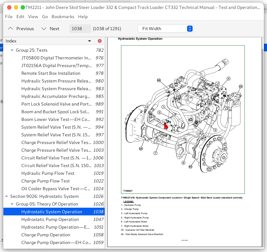
Hydrostatic System Operation....1038
Hydrostatic Pump Operation....1047
Hydrostatic Pump Operation—EH Controls....1051
Charge Pump Operation....1058
Charge Pump Operation—EH Controls....1059
Hydrostatic Motor Operation—Single Speed....1060
Hydrostatic Motor Operation—Single Speed—Compact Track Loader....1062
Hydrostatic Motor Operation—Two Speed....1065
Two Speed Proportional Solenoid Valve Operation....1071
Park Brake Solenoid Valve Manifold Operation....1075
Park Brake System Operation....1078
Park Brake System Operation—EH Controls....1079
Steering Control Operation....1082
Steering Control Operation—EH Controls....1084
Group 15: Diagnostic Information....1026
Diagnose Hydrostatic System Malfunctions....1086
Machine Does Not Move In Either Direction....1026
Hydrostatic Pump Or Hydrostatic Motor Noise....1026
Slow Response To Changes In Speed....1026
Low Power....1026
Wheels or Tracks Powered On One Side, Not The Other....1026
Machine Will Not Shift Into Or Out Of High Speed....1026
Machine Creeps With Steering Levers In Neutral....1026
Hydrostatic System Noise While In Neutral....1026
Steering Levers Hard To Move....1026
Steering Levers Feel Loose Or “Sloppy”....1026
Machine Tracks To One Side With Steering Levers In Full Forward Or Reverse Position....1026
Steering Levers Pulse Or Vibrate Excessively....1026
Park Brake Does Not Hold (Single Speed)....1026
Park Brakes Do Not Release (Single Speed)....1026
Grinding Noise While Operating Machine (Single Speed)....1026
Park Brake Does Not Hold (Two Speed)....1027
Park Brakes Do Not Release (Two Speed)....1027
Grinding Noise While Operating Machine (Two Speed)....1027
Machine Does Not Move In Either Direction—EH Controls....1027
Hydrostatic Pump Or Hydrostatic Motor Noise—EH Controls....1027
Slow Response To Changes In Speed—EH Controls....1027
Low Power—EH Controls....1027
Wheels or Tracks Powered On One Side, Not The Other—EH Controls....1027
Machine Will Not Shift Into Or Out Of High Speed—EH Controls....1027
Mistracking—EH Controls....1027
Park Brake Does Not Hold (Single Speed)—EH Controls....1027
Park Brakes Do Not Release (Single Speed)—EH Controls....1027
Grinding Noise While Operating Machine (Single Speed)—EH Controls....1027
Park Brake Does Not Hold (Two Speed)—EH Controls....1027
Park Brakes Do Not Release (Two Speed)—EH Controls....1027
Grinding Noise While Operating Machine (Two Speed)—EH Controls....1027
Group 25: Tests....1027
Hydrostatic Pump System Pressure Relief Test....1176
Hydrostatic Pump System Pressure Relief Test—EH Controls....1180
Hydrostatic Pump Flow Test....1184
Hydrostatic Pump Flow Test—EH Controls....1189
Wheel Speed Test—Skid Steer Loader....1194
Track Speed Test—Compact Track Loader....1197
Hydrostatic Pump Neutral Adjustment....1201
Hydrostatic Pump Mechanical Neutral Adjustment—EH Controls....1206
Hydrostatic Pump Control Neutral Adjustment—EH Controls....1212
Wheel Creep Adjustment—Skid Steer Loader....1215
Track Creep Adjustment—Compact Track Loader....1217
Steering Lever Effort Adjustment....1219
Centering Assembly Adjustment....1221
Steering Lever Adjustment—Centering....1225
Tracking Adjustment—Skid Steer Loader....1227
Tracking Adjustment—Compact Track Loader....1232
Auxiliary Hydraulic Handle Adjustment....1237
Hydraulic Control Handle Adjustment—Hands Only Machine....1239
Park Brake Release Pressure Test—Skid Steer Loader....1241
Park Brake Release Pressure Test—Compact Track Loader....1244
Park Brake Release Pressure Test—Skid Steer Loader—EH Controls....1248
Park Brake Release Pressure Test—Compact Track Loader—EH Controls....1251
Section 9031: Heating and Air Conditioning....1254
Group 05: Theory Of Operation....1254
Air Conditioning System Cycle Of Operation....1257
Group 15: Diagnostic Information....1254
Diagnose Air Conditioning System Malfunctions....1262
Diagnose Heater System Malfunctions....1265
Air Conditioner and Heater Component Location....1267
Group 25: Tests....1254
Refrigerant Cautions and Proper Handling....1270
Air Conditioner and Heater Operational Checks....1271
Refrigerant Leak Test....1275
Air Conditioner Compressor Clutch Test....1276
Air Conditioner High/Low Pressure Switch Test....1277
Air Conditioner Freeze Control Switch Test....1279
R134a Air Conditioning System Test....1280
Operating Pressure Diagnostic Chart....1282
Section 9900: Dealer Fabricated Tools....1284
Group 99: Dealer Fabricated Tools....1284
DFT1318 Motor Speed Sensor Test Harness....1287
DFT1325 Solenoid Power Harness....1289


