Ferrari 360 Modena/Spider 1992-2005 Factory Service & Shop Manual
Catalog:
Model:
Complete workshop repair service manual with electrical wiring diagrams for Ferrari 360 Modena / Spider 1992-2005. It's the same service manual used by dealers that guaranteed to be fully functional and intact without any missing page.
This service & repair manual (including maintenance, overhaul, disassembling & assembling, adjustment, tune-up, operation, inspecting, diagnostic & troubleshooting…) is divided into different sections. Each section covers a specific component or system with detailed illustrations. A table of contents is placed at the beginning of each section. Pages are easily found by category, and each page is expandable for great detail. The printer-ready PDF documents work like a charm on all kinds of devices.
MAKE: Ferrari
YEAR: 1992 1993 1994 1995 1996 1997 1988 1999 2000 2001 2002 2003 2004 2005
MODEL: 360 Modena / 360 Spider
LANGUAGE: EN/DE/FR/IT
FORMAT: PDF
"360 Workshop Manual.pdf"
1,428 pages
"360 Spider Electrical.pdf"
80 pages
"360 Modena Technical Updates.pdf"
328 pages
"360 Modena Spare Parts.pdf"
341 pages
"360 Modena Gear Box manual.pdf"
257 pages
"360 Spider Technical Update - Spare Parts.pdf"
28 pages
"360 Modena ECU error codes.pdf"
21 pages
EXCERPT:
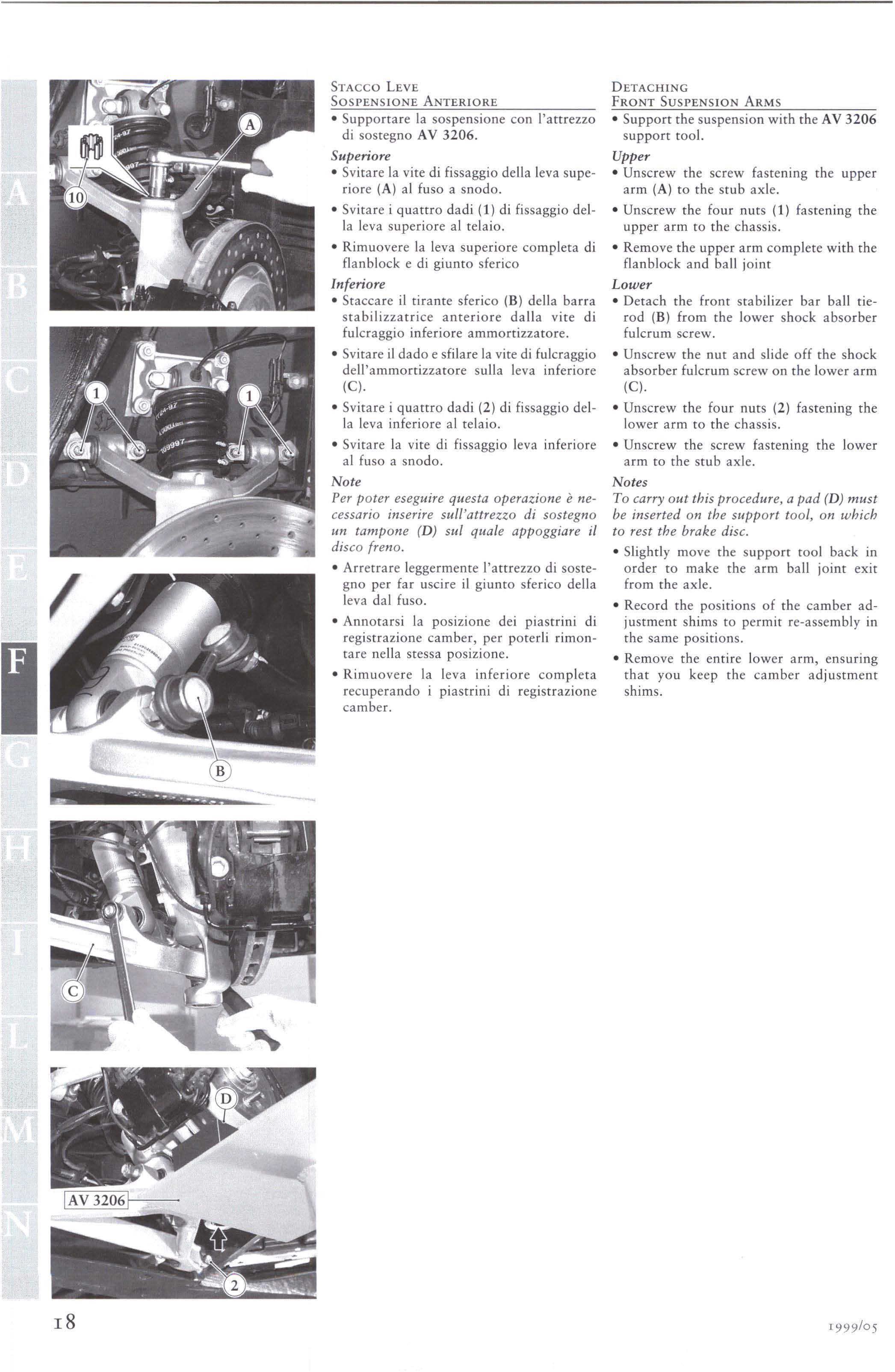
HUB-HOLDER-STUB AXLE
TIGHTENING TORQUES
Both components consist of a cast light alloy with housing for the wheel support bearing and the seats for the ball joints of the suspension arms and tie-rods for the steering box (stub axle) or the toe-in adjustment.
With each overhaul, ensure that the cast alloy is free of cracks or dents and that the threads are in good condition.
DISASSEMBLY
Stub axle
• Follow the procedure described for front wheel bearing replacement, -> F 3.03
in order to remove the stub axle from the front suspension system.
Hub-holder
• Follow the procedure described for rear wheel bearing replacement, -> F 3.04
in order to remove the hub-holder from the rear suspension system.
• The toe-in tie-rod ( 1) is fastened on the hub-holder. The fastening screw (2) must be unscrewed in order to remove it.
RE-ASSEMBLY
Stub axle
• Re-assemble the stub axle on the front bearing and on the suspension system -> F 3.03
Hub-holder
• Lubricate the fastening screw head and the toe-in tie-rod joint boot with FIAT MR3 grease.
• Insert the balancing ring (3) into the tired fastening screw seat.
• Install the toe-in tie-rod (1) in the hub-holder and tighten the screw (2) to the
prescribed torque.
• Re-assemble the hub-holder on the rear bearing and on the suspension system -> F 3.04
...


