John Deere PowerTech 10.5 L & 12.5 L Diesel Engines Lucas Electronic Fuel Systems With Lucas EUIs Component Technical Manual (CTM115)
Catalog:
Model:
Complete Component Technical Manual with Electrical Wiring Diagrams for John Deere PowerTech 10.5 L & 12.5 L Diesel EnginesLucas ElectronicFuel Systems With Lucas EUIs - (Worldwide Edition), with all the technical information to maintain, diagnose, repair, rebuild like professional mechanics.
John Deere PowerTech 10.5 L & 12.5 L Diesel EnginesLucas ElectronicFuel Systems With Lucas EUIs - (Worldwide Edition) workshop service repair manual includes:
* Numbered table of contents easy to use so that you can find the information you need fast.
* Detailed sub-steps expand on repair procedure information
* Numbered instructions guide you through every repair procedure step by step.
* Troubleshooting and electrical service procedures are combined with detailed wiring diagrams for ease of use.
* Notes, cautions and warnings throughout each chapter pinpoint critical information.
* Bold figure number help you quickly match illustrations with instructions.
* Detailed illustrations, drawings and photos guide you through every procedure.
* Enlarged inset helps you identify and examine parts in detail.
ctm115 - John Deere PowerTech 10.5 L & 12.5 L Diesel EnginesLucas ElectronicFuel Systems With Lucas EUIs - (Worldwide Edition) Component Technical Manual.pdf
ctm143 - John Deere Circuits d'alimentation électroniques Lucas des moteurs diesel PowerTech 10,5 l 12,5 l avec EUI Lucas -: (Édition mondiale).pdf
ctm142 - John Deere Motores diésel PowerTech de 10,5 l y Motores diésel de 12,5 l Sistemas de combustible electrónicos Lucas con inyectores Lucas -: (Edición mundial).pdf
ctm144 - John Deere PowerTech™ 10,5-l- u. 12,5-l-Dieselmotoren Elektronische Lucas- Kraftstoffsysteme mit Lucas-Pumpe-Düse-Einheiten -: (Weltweite Ausgabe).pdf
ctm145 - John Deere Motori diesel PowerTech da 10,5 e 12,5 l Impianti di alimentazione elettronici Lucas con unità elettronica iniettori Lucas -: (Edizione universale).pdf
PRODUCT DETAILS:
Total Pages: 507 pages
File Format: PDF (Internal Links, Bookmarked, Table of Contents, Searchable, Printable, high quality)
Category: CTM
Language: Spanish English French German Italian
Published on 2018/03/01
TABLE OF CONTENTS
Section 01: General Information...9
Group 000: Safety...9
Avoid Heating Near Pressurized Fluid Lines...12
Avoid High-Pressure Fluids...13
Avoid Hot Exhaust...14
Construct Dealer-Made Tools Safely...15
Decommissioning — Proper Recycling and Disposal of Fluids and Components...16
Follow Safety Instructions...17
Handle Agricultural Chemicals Safely...18
Handle Fluids Safely—Avoid Fires...20
Handling Batteries Safely...21
Illuminate Work Area Safely...23
Install All Guards...24
Live With Safety...25
Park Machine Safely...26
Practice Safe Maintenance...27
Precautions for Welding...29
Prepare for Emergencies...31
Prevent Acid Burns...32
Prevent Battery Explosions...34
Prevent Machine Runaway...35
Protect Against High Pressure Spray...36
Protect Against Noise...37
Recognize Safety Information...38
Remove Paint Before Welding or Heating...39
Replace Safety Signs...40
Service Cooling System Safely...41
Service Machines Safely...42
Stay Clear of Rotating Drivelines...43
Support Machine Properly...44
Understand Signal Words...45
Use Proper Lifting Equipment...46
Use Proper Tools...47
Use Steps and Handholds Correctly...48
Wait Before Opening High-Pressure Fuel System...49
Wear Protective Clothing...50
Work in Clean Area...51
Work In Ventilated Area...52
Group 001: Engine Identification...10
Engine Model Designation...55
Engine Serial Number Plate Information...57
Engine Option Code Label...59
Engine Application Chart...60
Distinguishing ECUs...61
Group 002: Fuels...10
Lubricants and Coolant...64
Diesel Fuel...65
Diesel Fuel Additive Products...66
Bio-Diesel Fuel...67
Lubricity of Diesel Fuel...69
Testing Diesel Fuel...70
Section 02: Repair and Adjustments...71
Group 090: Electronic Fuel System Repair and Adjustment...71
Fuel System Components...75
Replace Final (Secondary) Fuel Filter Element...77
Replacing Primary Fuel Filter/Water Separator...79
Remove and Install Air Purge Valve...81
Remove and Install Primary Fuel Filter Check Valve...83
Remove and Install Fuel System Surge Tank (6125ADW01/70 Engines)...84
Remove and Install Fuel Supply Pump...86
Remove and Install Fuel Manifold...88
Inspect Fuel Pressure Regulating Valve and Return Check Valve...90
Remove and Install Electronic Unit Injectors...93
Adjust Electronic Unit Injector Preload...98
Replace Electronic Unit Injector O-Rings...101
Replace Electronic Unit Injector Thrust Sleeve, Pad and O-Ring...102
Flush Fuel Rails...103
Bleed Fuel System...105
Group 110: Electrical Engine Control Repair and Adjustment...71
Lucas Electronic Control System...109
Remove and Install Coolant Temperature Sensor...111
Remove and Install Fuel Temperature Sensor...112
Remove and Install Oil Pressure Sensor...113
Remove and Install Manifold Air Temperature (MAT) Sensor...114
Remove and Install Manifold Absolute Pressure (MAP) Sensor...115
Remove and Install Camshaft Position Sensor...116
Remove and Install Crankshaft Position Sensor...117
Connectors...119
Use Electrical Insulating Compound...120
Using High-Pressure Washer...121
Connector Repair...122
Remove Blade Terminals from Connector Body...131
Repair (Pull Type) METRI-PACK™ Connectors...132
Repair (Push Type) METRI-PACK™ Connectors...135
Repair DEUTSCH Connectors...138
Section 03: Theory of Operation...142
Group 130: Electronic Fuel System Operation...142
About This Group...144
Low Pressure Fuel System Flow Diagram...145
Low Pressure Fuel Supply System Operation...147
Electronic Unit Injector (EUI) Operation...148
Group 140: Electrical Control System Operation...142
Electronic Control System Glossary of Terms...154
Electronic Control System Overview...156
Electronic Control System Operation...157
Monitoring Engine Parameters...158
Measuring Temperature...159
Measuring Manifold Air Pressure...162
Measuring Throttle Position...163
Determining Engine Airflow...164
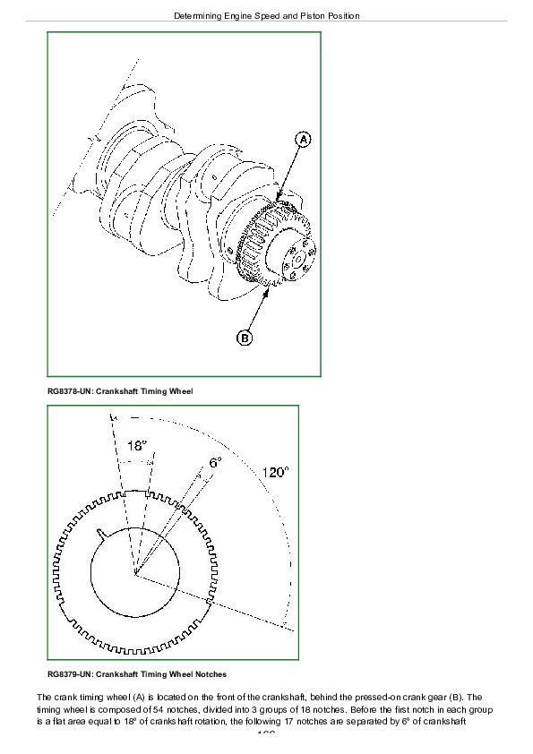
Determining Engine Speed and Piston Position...165
Engine Control Unit (ECU)...169
Pilot Injection Operation...171
Governor Modes...172
Maximum Fuel Quantity Control...173
Engine Control Unit (ECU) Self-Diagnosis...174
Section 04: Diagnostics...175
Group 150: Observable Diagnostics and Tests...175
Time study test block...178
About this Group of the Manual...179
Lucas ECU - Diagnosing Engine Malfunctions...175
Lucas ECU - Diagnosing Low Pressure Fuel System Malfunctions...175
B1 - ECU Does Not Communicate With DST...175
B2 - Engine Cranks/No Start or Starts Hard (DST Available)...175
B3 - Engine Cranks/No Start or Starts Hard (DST Not Available)...175
B4 - Engine Misfires/Runs Irregularly...175
B5 - Low Power/Excessive Black Smoke (DST Available)...175
B6 - Low Power/Excessive Black Smoke (DST Not Available)...175
B7 - Fuel Supply System Check...175
B8 - Excessive Fuel Filter Replacement...220
Check Fuel Supply Pressure...223
Bleed the Fuel System...224
Group 160: Trouble Code Diagnostics and Tests...175
About This Group of the Manual...226
Electrical Concepts...227
Electrical Circuit Malfunctions...228
Troubleshooting Circuit Malfunctions...231
Using a Digital Multimeter...235
Using the Break-Out-Box (BOB)...236
Cylinder Cutout Test Using JDG1250...237
Data Parameter Description...239
Diagnostic Scan Tool (DST) Engine Test Instructions—Cylinder Misfire Test...241
Diagnostic Scan Tool (DST) Engine Test Instructions—Relative Compression Test...243
Listing of Diagnostic Trouble Codes (DTCs)...245
John Deere Instrument (Gauge) Panel (Continued)...248
Diagnostic Procedure...249
Intermittent Fault Diagnostics...250
Engine 011 - Analog Throttle Input Voltage Too High...175
Engine 012 - Analog Throttle Input Voltage Too Low...175
Engine 013 - PWM Throttle Input Too High...176
Engine 014 - PWM Throttle Input Too Low...176
Engine 021 - MAP Input Voltage Too High...176
Engine 022 - MAP Input Voltage Too Low...176
Engine 023 - MAT Input Voltage Too High...176
Engine 024 - MAT Input Voltage Too Low...176
Engine 025 - ECT Input Voltage Too High...176
Engine 026 - ECT Input Voltage Too Low...176
Engine 027 - Fuel Rail Pressure Periodically Low...176
Engine 028 - Fuel Rail Pressure Continuously Low...176
Engine 031 - Cylinder 1 EUI Fault...176
Engine 032 - Cylinder 2 EUI Fault...176
Engine 033 - Cylinder 3 EUI Fault...176
Engine 034 - Cylinder 4 EUI Fault...176
Engine 035 - Cylinder 5 EUI Fault...176
Engine 036 - Cylinder 6 EUI Fault...176
Engine 037 - Fuel Temperature Input Voltage Too High...176
Engine 038 - Fuel Temperature Input Voltage Too Low...176
Engine 041 - Crank Position Input Missing...176
Engine 042 - Crank Position Input Out of Sync...176
Engine 043 - Cam Position Input Missing...176
Engine 044 - Cam Position Input Out of Sync...176
Engine 045 - Cam/Crank Inputs Out of Sync...176
Engine 050 - Fuel Rail Pressure Switch Fault...176
Engine 052 - MAP Input Voltage Erratic...176
Engine 053 - MAT Input Voltage Erratic...176
Engine 054 - ECT Input Voltage Erratic...176
Engine 055 - Fuel Temp Input Voltage Erratic...176
Engine 081 - Engine Control Unit (ECU) Error...176
Engine 084 - Power Down Error...176
Section 05: Tools...367
Group 170: Special Tools...367
JDG107...370
JDG139...371
JDG140...372
JDG141...373
JDG142...374
JDG143...375
JDG144...376
JDG145...377
JDG360...378
JDG361...379
JDG362...380
JDG363...381
JDG364...382
JDG707...383
JDG776...384
JDG777...385
JDG783...386
JDG785...387
JDG820...388
JDG865...389
JDG971...390
JDG998...391
JDG1334...392
JDG10466...393
JDG11100A...394
JDIS121...395
JDIS122...396
JT02171...397
JT03513C...398
JT05412...399
JT07306...400
JT07328...401
Section 06: Specifications...402
Group 200: Repair Specifications...402
Unified Inch Bolt and Screw Torque Values...405
Metric Bolt and Screw Torque Values...407
General OEM Engine Specifications...409
Fuel System Repair Specifications...410
Electronic Engine Control System Specifications...411
Group 210: Diagnostic Specifications...402
Fuel System Diagnostic Specifications...413
Torque Curve Selection...414
ECU Terminal Identification...416
6105H/6125H Engines Electronic Control System Component Location...418
10.5 L 10.5 L & 12.5 L Electronic Control System Wiring Diagram{pgNO}402 12.5 L Electronic Control System Wiring Diagram...419
10.5 L 10.5 L & 12.5 L OEM Application (With John Deere Instrument Panel) Electronic Control System Wiring Diagram{pgNO}402 12.5 L OEM Application (With John Deere Instrument Panel) Electronic Control System Wiring Diagram...420
John Deere PowerTech 10.5 L & 12.5 L Diesel Engines Lucas Electronic Fuel Systems With Lucas EUIs Component Technical Manual (CTM115)


