John Deere 748H Skidder Diagnosis and Test Service Technical Manual (TM10286)
Catalog:
Model:
Complete Diagnosis & Tests Technical Manual with electrical wiring diagrams for John Deere 748H Skidder, with workshop information to maintain, diagnose, and rebuild like professional mechanics.
John Deere 748H Skidder (S.N. —630435) workshop Diagnosis & Tests technical manual includes:
* Numbered table of contents easy to use so that you can find the information you need fast.
* Detailed sub-steps expand on repair procedure information
* Numbered instructions guide you through every repair procedure step by step.
* Troubleshooting and electrical service procedures are combined with detailed wiring diagrams for ease of use.
* Notes, cautions and warnings throughout each chapter pinpoint critical information.
* Bold figure number help you quickly match illustrations with instructions.
* Detailed illustrations, drawings and photos guide you through every procedure.
* Enlarged inset helps you identify and examine parts in detail.
TM10286 - John Deere 748H Skidder (S.N. —630435) Technical Manual - Diagnosis and Test.pdf
tm11044 - John Deere скиддера 748H ( —630435).pdf
tm10651 - John Deere Débusqueurs 748H (NS —630435).pdf
tm10652 - John Deere Remolcador de troncos 748H ( —630435).pdf
PRODUCT DETAILS:
Total Pages: 1,175 pages
File Format: PDF (bookmarked, ToC, Searchable, Printable)
Category: Operation and Test
Language: English Spanish French Russian
Published on 2018/09/06
TABLE OF CONTENTS
Section 9000: General Information...18
Group 01: Safety Information...18
Recognize Safety Information...21
Follow Safety Instructions...22
Operate Only If Qualified...23
Wear Protective Equipment...24
Avoid Unauthorized Machine Modifications...25
Inspect Machine...26
Stay Clear of Moving Parts...27
Avoid High-Pressure Oils...28
Avoid High-Pressure Fluids...29
Do Not Use Starting Fluid...30
Beware of Exhaust Fumes...31
Prevent Fires...32
Prevent Battery Explosions...33
Handle Chemical Products Safely...34
Dispose of Waste Properly...35
Prepare for Emergencies...36
Use Steps and Handholds Correctly...37
Start Only From Operator's Seat...38
Use and Maintain Seat Belt...39
Prevent Unintended Machine Movement...40
Avoid Work Site Hazards...41
Operate Machine Safely...42
Keep Riders Off Machine...43
Avoid Backover Accidents...44
Avoid Machine Tip Over...45
Operating on Slopes...47
Operating or Traveling On Public Roads...48
Inspect and Maintain ROPS...49
Keep the Operator Protective Structure (OPS) in Place...50
Add and Operate Attachments Safely...51
Park and Prepare for Service Safely...52
Service Cooling System Safely...54
Remove Paint Before Welding or Heating...55
Make Welding Repairs Safely...56
Drive Metal Pins Safely...57
Section 9001: Diagnostic Trouble Codes (DTC)...58
Group 10: Engine Control Unit (ECU)...58
Engine Control Unit (ECU) Diagnostic Trouble Codes...63
000091.03 - Throttle Voltage Out of Range High...58
000091.04 - Throttle Voltage Out of Range Low...58
000647.05 - Fan Proportional Solenoid Out of Range Low...58
000647.30 - Reversing Fan Switch Active Too Long...58
000676.03 - Glow Plug Relay Out of Range High...58
000676.05 - Glow Plug Relay Out of Range Low...58
001075.05 - Low Pressure Fuel Pump Out of Range Low...58
001075.06 - Low Pressure Fuel Pump Out of Range High...58
002003.09 - TCU Communication Data Error...58
002003.13 - TCU Communication Calibrate Error...58
002017.09 - SDM Communication Data Error...58
002017.13 - SDM Communication Calibrate Error...58
002883.03 - Engine Speed Switch Out of Range High...58
002883.04 - Engine Speed Switch Out of Range Low...58
Group 20: Transmission Control Unit (TCU)...58
Transmission Control Unit (TCU) Diagnostic Trouble Codes...101
000177.12 - Oil Temp Sensor Out of Range...58
000525.02 - Shift Parameter Erratic or Bad Data...58
000525.12 - Request for an Unidentified Shift Being Made...58
002000.09 - ECU Communication Data Error...58
002000.13 - ECU Communication Calibrate Error...58
298626.03 - Park and Not Park Active Out of Range High...58
298626.04 - Park and Not Park Active Out of Range Low...58
298678.04 - Clutch Valve Supply Voltage Out of Range Low...58
298808.31 - Output Speed Sensor Condition Exists...58
298809.31 - Starter Input Signal High...58
298810.05 - Solenoid C Out of Range Low...58
298810.06 - Solenoid C Out of Range High...58
298811.05 - Solenoid B Out of Range Low...58
298811.06 - Solenoid B Out of Range High...58
298812.05 - Solenoid A Out of Range Low...59
298812.06 - Solenoid A Out of Range High...59
298813.05 - Solenoid 4 Out of Range Low...59
298813.06 - Solenoid 4 Out of Range High...59
298814.05 - Solenoid 3 Out of Range Low...59
298814.06 - Solenoid 3 Out of Range High...59
298815.05 - Solenoid 2 Out of Range Low...59
298815.06 - Solenoid 2 Out of Range High...59
298818.31 - Directional Clutch Slip Condition Exists...59
298819.31 - Speed Clutch Slip Condition Exists...59
298903.31 - Inching Pedal Switch Input Invalid...59
298904.03 - Inching Pedal Potentiometer Out of Range High...59
298904.04 - Inching Pedal Potentiometer Out of Range Low...59
298907.31 - Not Park and Park Pressure Inputs Passive...59
298919.31 - Not Park and Park Pressure Inputs Active...59
298925.31 - Shifter Neutral and Reverse Inputs Active...59
298926.31 - Shifter Neutral and Forward Inputs Active...59
298927.31 - Neutral Forward Reverse Inputs Passive...59
298928.31 - Upshift and Downshift Inputs Active...59
298931.31 - Output Speed Sensor Out of Range...59
298932.31 - Calibration Without Park Brake Applied...59
298933.31 - EEPROM Shift Parameter Condition...59
298934.03 - Solenoid Group 3 Out of Range High...59
298934.04 - Solenoid Group 3 Out of Range Low...59
298935.03 - Solenoid Group 2 Out of Range High...59
298935.04 - Solenoid Group 2 Out of Range Low...59
298936.03 - Solenoid Group 1 Out of Range High...59
298936.04 - Solenoid Group 1 Out of Range Low...59
298937.31 - Hold Clutch Pressure Condition...59
298939.31 - Calibrating Clutch Pressure Condition...59
298940.31 - Clutch D Fast Full Time Condition...59
298941.31 - Clutch C Fast Fill Time Condition...59
298942.31 - Clutch B Fast Fill Time Condition...59
298943.31 - Clutch A Fast Fill Time Condition...60
298944.31 - Clutch 4 Fast Fill Time Condition...60
298945.31 - Clutch 3 Fast Fill Time Condition...60
298946.31 - Clutch 2 Fast Fill Time Condition...60
298947.31 - Clutch 1 Fast Fill Time Condition...60
298948.31 - Cylinder Speed With Reverse Clutch Condition...60
298949.31 - Cylinder Speed With Forward Clutch Condition...60
298950.31 - Cylinder Speed Condition...60
298951.31 - Engine Speed Too Low For Calibration...60
298952.31 - Engine Speed Too High For Calibration...60
298953.31 - Sump Temp Too Low For Calibration...60
298954.05 - Solenoid 1 Out of Range Low...60
298954.06 - Solenoid 1 Out of Range High...60
298955.05 - Solenoid D Out of Range Low...60
298955.06 - Solenoid D Out of Range High...60
299359.31 - Forward and Reverse Inputs Active...60
523120.16 - Clutch Temperature Moderately High Value...60
523656.05 - Dual Mode Steer Output Out of Range Low...60
523656.06 - Dual Mode Steer Output Out of Range High...60
523689.04 - Differential Lock Short to Ground...60
523925.03 - Dual Mode Steer Switch Out of Range High...60
523925.04 - Dual Mode Steer Switch Out of Range Low...60
523697.09 - Top of Clutch Input Passive Abnormal Data Rate...60
Group 30: Standard Display Monitor (SDM)...60
Standard Display Monitor (SDM) Diagnostic Trouble Codes...260
000096.03 - Fuel Level Sensor Out of Range High...60
000096.04 - Fuel Level Sender Out of Range Low...60
000107.00 - Engine Air Filter Restriction Data Above Normal...60
000126.00 - Transmission Oil Filter Restriction Data Above Normal...60
000158.00 - System Voltage Data Above Normal...60
000158.01 - System Voltage Data Below Normal...60
000911.00 - Engine Air Filter Data Above Normal...60
001508.00 - Hydraulic Reservoir Oil Temperature Sensor Data Above Normal...60
001508.03 - Hydraulic Reservoir Oil Temperature Sensor Out of Range High...61
001508.04 - Hydraulic Reservoir Oil Temperature Sensor Out of Range Low...61
001508.16 - Hydraulic Oil Temp Sensor Moderately High Value...61
001713.00 - Hydraulic Oil Filter Restriction Data Above Normal...61
002000.09 - ECU Communication Data Error...61
002000.13 - ECU Communication Calibrate Error...61
002003.09 - TCU Communication Data Error...61
002003.13 - TCU Communication Calibrate Error...61
Section 9005: Operational Checkout...307
Group 10: Operational Checks...307
Complete Machine Operational Checkout...369
Section 9010: Engine...430
Group 05: Theory of Operation...430
Engine Fuel System Component Location...433
Engine Cooling System Component Location...435
Engine Fluid Sample Port Locations...436
Cold Weather Starting Aid...437
Group 15: Diagnostic Information...430
PowerTech Plus™ 4.5 L and 6.8 L (4045 and 6068) John Deere Engines...439
Engine Will Not Crank...430
Engine Coolant Temperature Above Normal...430
Engine Coolant Temperature Below Normal...430
Group 25: Tests...430
Fuel Line Leakage Test...447
Air Intake System Leakage Test...448
Air Filter Restriction Switch Test...451
Engine Slow and Fast Idle Speed Check...454
Section 9015: Electrical System...455
Group 05: System Information...455
Electrical Diagram Information...464
Group 10: System Diagrams...455
Fuse Specifications...472
System Functional Schematic, Wiring Diagrams and Component Locations Legend...474
System Functional Schematic and Section Legend...480
Cab Roof Harness (W9) Component Location...492
Cab Roof Harness (W9) Wiring Diagram...494
Load Center Harness (W10) Component Location...496
Load Center Harness (W10) Wiring Diagram...498
Engine Interface Harness (W11) Component Location...501
Engine Interface Harness (W11) Wiring Diagram...502
Engine Harness (W12) Component Location...504
Engine Harness (W12) Wiring Diagram...506
Transmission Harness (W13) Component Location...508
Transmission Harness (W13) Wiring Diagram...509
Hydraulic Reservoir Harness (W14) Component Location...510
Hydraulic Reservoir Harness (W14) Wiring Diagram...511
Fuel Sensor and Backup Alarm Harness (W15) Component Location...512
Fuel Sensor and Backup Alarm Harness (W15) Wiring Diagram...513
Radio Harness (W17) Component Location...514
Radio Harness (W17) Wiring Diagram...515
Secondary Steering Harness (W19) Component Location...516
Secondary Steering Harness (W19) Wiring Diagram...517
Grapple Rotate and Open/Close Harness (W24) Component Location—Pilot Control...519
Grapple Rotate and Open/Close Harness (W24) Wiring Diagram—Pilot Control...521
Grapple Rotate Harness (W25) Component Location—Mechanical Linkage...522
Group 15: Sub-System Diagnostics...455
Power and Charging Circuits Theory of Operation...527
Start Circuit Theory of Operation...531
Park Brake Circuit Theory of Operation...534
Controller Area Network (CAN) Circuit Theory of Operation...537
Engine Control Unit (ECU) Circuits Theory of Operation...539
Proportional Fan Speed and Reversing Fan Circuits Theory of Operation...549
Transmission Control Unit (TCU) Circuits Theory of Operation...552
Standard Display Monitor (SDM) Circuits Theory of Operation...557
Grapple Control Circuit Theory of Operation...560
Secondary Steering Circuit Theory of Operation...562
Dual Mode Steer Circuit Theory of Operation...564
De-clutch Circuit Theory of Operation (S.N. 620843—)...566
Group 16: Monitor Operation...456
Standard Display Monitor (SDM) Operation...571
Standard Display Monitor (SDM) Menu Structure—Service Mode...575
Standard Display Monitor (SDM)—Temperature Format...579
Standard Display Monitor (SDM)—Change Units...581
Standard Display Monitor (SDM)—Hide—Unhide Main Menu...582
Group 20: References...456
Electrical Component Specifications...587
Diagnostic Trouble Codes (DTC) Quick Reference List...590
Service ADVISOR™ Connection Procedure...595
Intermittent Diagnostic Trouble Code (DTC) Diagnostics...598
Reading Diagnostic Trouble Codes with Service ADVISOR™ Diagnostic Application...599
Transmission Diagnostic Trouble Codes—Limp Home Mode and Inchless Power Shift...600
Calibration of Transmission Control Unit (TCU)...601
Troubleshooting Transmission Gear Solenoid Diagnostic Trouble Codes...604
CAN Circuit Test...606
Two-Wire Sensor Circuit Check Using Standard Display Monitor (SDM) or SERVICE ADVISOR SERVICE ADVISOR is a trademark of Deere & Company...456
Three-Wire Sensor Circuit Check Using Standard Display Monitor (SDM) or SERVICE ADVISOR SERVICE ADVISOR is a trademark of Deere & Company...456
Bump Shifter Test...612
Bump Shifter Default Gear Selection...614
Relay Test...616
Diode Test...618
Diode Module Test...619
Alternator Test...621
Battery Test Procedure...622
Connector Terminal Test...623
Remove and Install Transmission Control Unit (TCU)...626
Remove and Install Engine Control Unit (ECU)...628
Remove and Install Single Lever Pilot Control Relays...629
Replace DEUTSCH DEUTSCH is a trademark of Deutsch Co. Rectangular or Triangular Connectors...457
Replace DEUTSCH DEUTSCH is a trademark of the Deutsch Co. Connectors...457
Install DEUTSCH DEUTSCH is a trademark of the Deutsch Co. Contact...457
Replace WEATHER PACK WEATHER PACK is a trademark of Packard Electric. Connector...457
Replace SURE-SEAL SURE-SEAL is a trademark of ITT Cannon Electric. Connector with WEATHER PACK WEATHER PACK is a trademark of Packard Electric. Connector...457
Install WEATHER PACK WEATHER PACK is a trademark of Packard Electric. Contact...457
Remove Connector Body from Blade Terminals...642
Crimper Tool For Transmission Control Unit Connector—Operation...643
Crimper Tool For Transmission Control Unit Connector—Remove And Install Die Set...644
Crimper Tool For Transmission Control Unit Connector—Contact Support Adjustment...646
Crimper Tool For Transmission Control Unit Connector—Crimping Procedure...647
Crimper Tool For Transmission Control Unit Connector—Crimp Height Inspection...650
Crimper Tool For Transmission Control Unit Connector—Crimp Height Adjustment...651
Replace Transmission Control Unit Connector Terminals...653
Cinch CP Connector Assemble...655
Cinch CP Connector Terminal Removal...662
Cinch CP Connector Terminal Hand Crimp Process...665
Transmission Control Unit (TCU) Remove and Install...669
Engine Control Unit (ECU) Remove and Install...671
Single Lever Pilot Control Relays Remove and Install...672
Section 9020: Power Train...673
Group 05: Theory of Operation...673
Power Train Component Overview...677
DF180 Series Powershift Transmission...678
TeamMate Axles...679
Transmission Operation...680
Transmission Component Identification...681
Transmission Diagram...683
Transmission Hydraulic System Operation...843
Transmission Charge Pump Operation...688
Transmission Filter Bypass Valve Operation...690
Transmission Control Valve Port Identification...692
Transmission Proportional Solenoid Valves Identification...694
Transmission Control Valve Operation...695
Transmission Pressure Regulator Valve Operation...697
Park Brake and Differential Lock Control Valve...699
Park Brake Control Circuit...701
Park Brake Manual Release Operation...706
Differential Lock Control Circuit...708
Cold Weather Transmission Disconnect Operation—If Equipped...712
Group 15: Diagnostic Information...673
Transmission Overfills With Oil...673
Transmission Clutch Slippage...673
Transmission Shifts Too Slow...673
Transmission Shifts Too Fast...673
Park Brake Activates When Service Brakes Are Applied (No Load on Engine While in Gear)...673
Machine Will Not Move (Load on Engine or Engine Stalls When Shifted Into Gear)...673
Machine Creeps in Neutral (Load Put on Engine When Service Brakes are Applied)...673
Transmission System Overheats...673
Lube Pressure Low, Transmission Charge Pressure Normal...673
Excessive Transmission Noise Under Load or No Load...673
Machine Makes Excessive Transmission Noise When Moving...673
Erratic Transmission Oil Pressure...673
Excessive Transmission Oil Pressure...674
Low Transmission Oil Pressure in All Gears...674
Low Transmission Oil Pressure in One Gear but Correct in Other Gears...674
Transmission Oil Cooler Externally Leaking...674
Transmission Breather Oil Leakage...674
Filter or Filter Oil Lines Blow Out...674
Low Lube Pressure (Not All Gears)...674
Excessive Lube Pressure (Not All Gears)...674
Low Transmission Oil Cooler Inlet Pressure, Correct Lube Pressure...674
Low Transmission Oil Cooler Inlet Pressure and Lube Pressure...674
Machine “Jumps” When Inching Pedal Engaged...674
Machine Lacks Power...674
Excessive Machine Vibration...674
Diagnose Cold Weather Disconnect Malfunctions...674
Excessive Drive Line Vibration...674
Park Brake Comes On While Using a Hydraulic Function...674
Park Brake Engages While Machine Is Moving...674
Park Brake Will Not Release...674
No Differential Lock Operation...674
Differential Lock Slippage...674
Excessive Differential and/or Axle Noise...674
Oil Seepage From Outer Axle Seal...674
Power Train Component Location...798
Group 20: Adjustments...674
Inching Pedal Adjustment...803
Park Brake Manual Release Procedure...806
Cold Weather Disconnect Linkage Adjustment—If Equipped...811
Group 25: Tests...674
Transmission Oil Warm-Up Procedure...815
Transmission Pump Flow Test...816
Transmission System Pressure Test...819
Transmission Lube Circuit Pressure Test...821
Transmission Control Circuit Pressure Test...824
Transmission Cooler Relief Valve Pressure Test...827
Park Brake Pressure Test...829
Differential Lock Pressure Test...833
Section 9025: Hydraulic System...838
Group 05: Theory of Operation...838
Hydraulic System Operation...843
Main Pump and Reservoir Hydraulic Circuit Operation...844
Cooling Loop and Reversing Fan Circuit Operation...846
Service Brake Hydraulic Circuit Operation...848
Steering and Secondary Steering Hydraulic Circuit Operation...850
Dual Mode Steering Hydraulic Circuit Operation...852
Pilot Control Hydraulic Circuit Operation...855
Grapple Rotate Hydraulic Circuit Operation...858
Main Hydraulic Pump and Pressure Compensator Operation...859
Brake Accumulator Operation...862
Hydraulic Reservoir Operation...863
Hydraulic Oil Return Filter Operation...865
Hydraulic Fan Filter Operation...867
Brake Valve Operation...868
Priority Valve Operation...871
Steering Valve and System Operation...875
Secondary Steering Inlet Manifold Operation...877
120 Series Cylinder Operation...879
Blade Manually Operated Valve Section Operation...881
Arch and Boom Pilot Operated Valve Section Operation...883
System Relief Valve Operation...884
Circuit Relief Valve—Adjustable with Anticavitation Operation...886
Circuit Relief Valve—Non-Adjustable Operation...888
Grapple Tong Flow Divider Operation...889
Pilot Controller Operation...891
Grapple Rotate Solenoid Valve Operation...892
Dual Mode Steering Solenoid Valve Operation...894
Rotary Manifold Operation...896
Fan Pump Operation...897
Fan Variable Speed and Reversing Manifold Operation...900
Reversing Fan Motor Operation...902
Hydraulic Oil Cooler Operation...903
Cab Tilt Circuit Operation...904
Group 15: Diagnostic Information...839
Hydraulic System Overheating...839
Hydraulic Function Drifts Down...839
No Steering or Hydraulic Functions...839
Hydraulic Functions Slow...839
Individual Functions Slow (Cycle Time Slow)...839
No Hydraulic Functions (Steering Normal)...839
Low Hydraulic Power (Pressure)...839
Excessive Hydraulic Pump Noise...839
Function Powers Up or Down Without Moving Lever...839
Grapple Rotate Stalls...839
Grapple Rotates Too Fast...839
Grapple Rotates Slow...839
Tongs Do Not Close Evenly...839
Tongs Open or Close Slowly...839
Grapple Loses Logs During Skidding...839
Transmission Overfills With Oil...839
No Steering (Hydraulic Functions Normal)...839
Steering Valve Does Not Center...839
Steering Valve Locks Up...839
Frames Turn Wrong Direction...839
Steering Slow or Hard...839
Steering Erratic or Spongy...839
Machine Wanders...839
Quick Steer Mode Not Engaging...839
Quick Steer Mode Not Engaging...839
Quick Steer Mode Not Disengaging...839
Quick Steer Mode Engaging When Disengaged...839
Poor or No Brakes (Other Hydraulic Systems Normal)...839
Brakes Overly Aggressive...839
Brakes Drag...839
Brakes Chatter or Noisy...840
Delay in Braking...840
Fan Does Not Reach Full Speed (Both Directions)...840
Fan Does Not Reach Full Speed (Forward Direction Only)...840
Fan Does Not Reach Full Speed (Reverse Direction Only)...840
Fan Does Not Spin (Both Directions)...840
Fan Does Not Slow Down Before Reversing...840
High Cooler Pressure or Pressure Spikes...840
High Return Pressure at Fan Reversing Manifold Port T...840
High Flow From Fan Motor Case Drain...840
Fan Pump is Cavitating...840
Hydraulic System Component Location...985
Hydraulic System Schematic...988
Group 20: Adjustments...840
Service Brake Pedal Adjustment...993
Service Brake Inspection and Adjustment...994
Service Brake Bleeding Procedure...995
Grapple Dampener Adjustment...999
Group 25: Tests...840
D15032NU Vacuum Pump Installation...1003
JT02156A Digital Pressure and Temperature Analyzer Installation...1004
JT07148 Digital Hydraulic Tester...1006
Hydraulic Oil Warm-Up Procedure...1007
Main Hydraulic Pump Identification...1008
Main Hydraulic Pump Standby Pressure Test...1009
Main Hydraulic Pump Flow Test...1012
Main Hydraulic Pump Leakage Test...1015
Pressure Reducing Valve Pressure Test...1017
Pilot Controller Pressure Test...1019
Priority Valve and Relief Valve Pressure Test...1022
Priority Valve "LS" Port Flow Test...1025
Priority Valve and Relief Valve Leakage Test...1027
System and Circuit Relief Valve Pressure Test...1029
Hydraulic Component Leakage Test...1034
Cylinder Leakage Test...1038
Cylinder Drift Test...1040
Dual Mode Steering Engagement Pressure Test...1042
Grapple Rotate Motor Crossover Relief Valve Pressure Test...1045
Grapple Rotate Solenoid Valve Neutral Leakage Test...1047
Grapple Tong Flow Divider Relief Valve Test...1049
Rotary Manifold Center Seal Leakage Test...1051
Rotary Manifold Drain and Lower Seal Leakage Test...1053
Service Brake Valve and Accumulator Pressure Test...1055
Service Brake Valve Leakage Test...1058
Steering Valve Neutral Leakage Test...1061
Hydraulic Functions Cycle Time Test...1063
Hydraulic Oil Filter Inspection Procedure...1065
Cooling Fan Circuit Test Procedure...1066
Fan Motor Case Drain Test...1071
Secondary Steering Operation Test...1073
Section 9030: Winch...1076
Group 05: Theory of Operation...1076
John Deere 4000 and 6000 Winches...1078
Group 15: Diagnostic Information...1076
Winch Control Lever Effort Excessive...1076
Winch Clutch Slips...1076
Winch Free Spool Effort Excessive...1076
Winch Brake Will Not Hold...1076
Winch Will Not Free Spool...1076
Transmission Oil Level Varies Excessively...1076
Winch Makes Grinding Noise When Going from FREE SPOOL to BRAKE OFF...1076
Winch Component Location...1094
Winch Hydraulic Schematic...1095
Group 20: Adjustments...1076
Winch Control Cable Adjustment Check...1097
Brake Off Adjustment—4000 Series Winch...1098
Brake Off Adjustment—6000 Series Winch...1103
Group 25: Test...1076
Winch System Pressure Test...1112
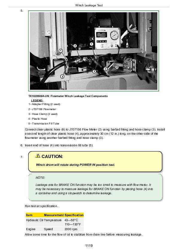
Winch Leakage Test...1117
Winch Drum Rolling Drag Test...1121
Section 9031: Heating and Air Conditoning...1123
Group 05: Theory Of Operation...1123
Air Conditioning System Cycle Of Operation...1126
Group 15: Diagnostic Information...1123
Diagnose Air Conditioning System Malfunctions...1123
Diagnose Heater System Malfunctions...1123
Air Conditioning System Component Location...1153
Group 25: Tests...1123
Air Conditioning System Checks...1158
R134a Air Conditioning System Test...1161
Air Conditioner Freeze Control Switch Test...1165
Air Conditioning Compressor Clutch Test...1167
Air Conditioning High/Low Pressure Switch Test...1168
Air Conditioning Expansion Valve Test...1170
Refrigerant Leak Test...1173
John Deere 748H Skidder Diagnosis and Test Service Technical Manual (TM10286)


