John Deere 540H and 548H Skidder ( —630435) Technical Manual (TM11329)
Catalog:
Model:
John Deere 540H and 548H Skidder ( —630435) is divided into different sections. Each section covers a specific component or system with detailed illustrations. A table of contents is placed at the beginning of each section. Pages are easily found by category, and each page is expandable for great detail. The printer-ready PDF documents work like a charm on all kinds of devices. This document is printable, without restrictions, contains searchable text, bookmarks, crosslinks for easy navigation.
TM11329 - John Deere 540H and 548H Skidder ( —630435) Technical Manual.pdf
tm11331 - John Deere Débusqueurs 540H et 548H ( —630435).pdf
tm11395 - John Deere Skidder 540H und 548H ( —630435).pdf
tm11332 - John Deere Remolcadores de troncos 540H y 548H ( —630435).pdf
Category: Operation and Test
Language: English Spanish French German
Published on 2018/09/06
TABLE OF CONTENTS
Section 9000: General Information...18
Group 01: Safety...18
Recognize Safety Information...21
Follow Safety Instructions...22
Operate Only If Qualified...23
Wear Protective Equipment...24
Avoid Unauthorized Machine Modifications...25
Inspect Machine...26
Stay Clear of Moving Parts...27
Avoid High-Pressure Fluids...28
Avoid High-Pressure Oils...29
Do Not Use Starting Fluid...30
Beware of Exhaust Fumes...31
Prevent Fires...32
Clean Debris from Machine...33
Prevent Battery Explosions...34
Handle Chemical Products Safely...35
Dispose of Waste Properly...36
Prepare for Emergencies...37
Use Steps and Handholds Correctly...38
Start Only From Operator's Seat...39
Use and Maintain Seat Belt...40
Prevent Unintended Machine Movement...41
Avoid Work Site Hazards...42
Operate Machine Safely...43
Keep Riders Off Machine...44
Avoid Backover Accidents...45
Avoid Machine Tip Over...46
Operating on Slopes...48
Operating or Traveling On Public Roads...49
Inspect and Maintain ROPS...50
Keep the Operator Protective Structure (OPS) in Place...51
Add and Operate Attachments Safely...52
Park and Prepare for Service Safely...53
Service Tires Safely...55
Service Cooling System Safely...56
Remove Paint Before Welding or Heating...57
Make Welding Repairs Safely...58
Drive Metal Pins Safely...59
Section 9001: Diagnostic Trouble Codes (DTC)...60
Group 10: Engine Control Unit (ECU) Diagnostic Trouble Codes...65
Engine Control Unit (ECU) Diagnostic Trouble Codes...65
000091.03 - Throttle Voltage Out of Range High...60
000091.04 - Throttle Voltage Out of Range Low...60
000647.05 - Fan Proportional Solenoid Out of Range Low...60
000647.30 - Reversing Fan Switch Active Too Long...60
000676.03 - Glow Plug Relay Out of Range High...60
000676.05 - Glow Plug Relay Out of Range Low...60
001075.05 - Low Pressure Fuel Pump Out of Range Low...60
001075.06 - Low Pressure Fuel Pump Out of Range High...60
002003.09 - TCU Communication Data Error...60
002003.13 - TCU Communication Calibrate Error...60
002017.09 - SDM Communication Data Error...60
002017.13 - SDM Communication Calibrate Error...60
002883.03 - Engine Speed Switch Out of Range High...60
002883.04 - Engine Speed Switch Out of Range Low...60
Group 20: Transmission Control Unit (TCU) Diagnostic Trouble Codes...107
Transmission Control Unit (TCU) Diagnostic Trouble Codes...107
000177.12 - Oil Temp Sensor Out of Range...60
000525.02 - Shift Parameter Erratic or Bad Data...60
000525.12 - Request for an Unidentified Shift Being Made...60
002000.09 - ECU Communication Data Error...60
002000.13 - ECU Communication Calibrate Error...60
298626.03 - Park and Not Park Active Out of Range High...60
298626.04 - Park and Not Park Active Out of Range Low...60
298678.04 - Clutch Valve Supply Voltage Out of Range Low...60
298808.31 - Output Speed Sensor Condition Exists...60
298809.31 - Starter Input Signal High...60
298810.05 - Solenoid C Out of Range Low...60
298810.06 - Solenoid C Out of Range High...60
298811.05 - Solenoid B Out of Range Low...60
298811.06 - Solenoid B Out of Range High...60
298812.05 - Solenoid A Out of Range Low...61
298812.06 - Solenoid A Out of Range High...61
298813.05 - Solenoid 4 Out of Range Low...61
298813.06 - Solenoid 4 Out of Range High...61
298814.05 - Solenoid 3 Out of Range Low...61
298814.06 - Solenoid 3 Out of Range High...61
298815.05 - Solenoid 2 Out of Range Low...61
298815.06 - Solenoid 2 Out of Range High...61
298818.31 - Directional Clutch Slip Condition Exists...61
298819.31 - Speed Clutch Slip Condition Exists...61
298903.31 - Inching Pedal Switch Input Invalid...61
298904.03 - Inching Pedal Potentiometer Out of Range High...61
298904.04 - Inching Pedal Potentiometer Out of Range Low...61
298907.31 - Not Park and Park Pressure Inputs Passive...61
298919.31 - Not Park and Park Pressure Inputs Active...61
298925.31 - Shifter Neutral and Reverse Inputs Active...61
298926.31 - Shifter Neutral and Forward Inputs Active...61
298927.31 - Neutral Forward Reverse Inputs Passive...61
298928.31 - Upshift and Downshift Inputs Active...61
298929.31 - Bottom of Clutch Input Passive...61
298931.31 - Output Speed Sensor Out of Range...61
298932.31 - Calibration Without Park Brake Applied...61
298933.31 - EEPROM Shift Parameter Condition...61
298934.03 - Solenoid Group 3 Out of Range High...61
298934.04 - Solenoid Group 3 Out of Range Low...61
298935.03 - Solenoid Group 2 Out of Range High...61
298935.04 - Solenoid Group 2 Out of Range Low...61
298936.03 - Solenoid Group 1 Out of Range High...61
298936.04 - Solenoid Group 1 Out of Range Low...61
298937.31 - Hold Clutch Pressure Condition...61
298939.31 - Calibrating Clutch Pressure Condition...61
298940.31 - Clutch D Fast Fill Time Condition...61
298941.31 - Clutch C Fast Fill Time Condition...61
298942.31 - Clutch B Fast Fill Time Condition...62
298943.31 - Clutch A Fast Fill Time Condition...62
298944.31 - Clutch 4 Fast Fill Time Condition...62
298945.31 - Clutch 3 Fast Fill Time Condition...62
298946.31 - Clutch 2 Fast Fill Time Condition...62
298947.31 - Clutch 1 Fast Fill Time Condition...62
298948.31 - Cylinder Speed With Reverse Clutch Condition...62
298949.31 - Cylinder Speed With Forward Clutch Condition...62
298950.31 - Cylinder Speed Condition...62
298951.31 - Engine Speed Too Low For Calibration...62
298952.31 - Engine Speed Too High For Calibration...62
298953.31 - Sump Temp Too Low For Calibration...62
298954.05 - Solenoid 1 Out of Range Low...62
298954.06 - Solenoid 1 Out of Range High...62
298955.05 - Solenoid D Out of Range Low...62
298955.06 - Solenoid D Out of Range High...62
299359.31 - Forward and Reverse Inputs Active...62
523120.16 - Clutch Temperature Moderately High Value...62
523656.05 - Dual Mode Steer Output Out of Range Low...62
523656.06 - Dual Mode Steer Output Out of Range High...62
523689.04 - Differential Lock Short to Ground...62
523925.03 - Dual Mode Steer Switch Out of Range High...62
523925.04 - Dual Mode Steer Switch Out of Range Low...62
523697.09 - Top of Clutch Input Passive Abnormal Data Rate...62
Group 30: Standard Display Monitor (SDM) Diagnostic Trouble Codes...285
Standard Display Monitor (SDM) Diagnostic Trouble Codes...285
000096.03 - Fuel Level Sensor Out of Range High...62
000096.04 - Fuel Level Sensor Out of Range Low...62
000107.00 - Engine Air Filter Restriction Data Above Normal...62
000126.00 - Transmission Oil Filter Restriction Data Above Normal...62
000158.00 - System Voltage Data Above Normal...62
000158.01 - System Voltage Data Below Normal...62
001508.00 - Hydraulic Reservoir Oil Temperature Sensor Data Above Normal...62
001508.03 - Hydraulic Reservoir Oil Temperature Sensor Out of Range High...63
001508.04 - Hydraulic Reservoir Oil Temperature Sensor Out of Range Low...63
001508.16 - Hydraulic Oil Temp Sensor Moderately High Value...63
001713.00 - Hydraulic Oil Filter Restriction Data Above Normal...63
002000.09 - ECU Communication Data Error...63
002000.13 - ECU Communication Calibrate Error...63
002003.09 - TCU Communication Data Error...63
Section 9005: Operational Checkout...330
Group 10: Operational Checks...330
Complete Machine Operational Checkout...390
Section 9010: Engine...449
Group 05: Theory of Operation...449
PowerTech Plus™ 6.8L (6068) John Deere Engine—6.8L Tier 3/Stage IIIA...467
Engine Fuel System Component Location...452
Engine Cooling System Component Location...454
Engine Fluid Sample Port Locations...455
Cold Weather Starting Aid...456
Group 15: Diagnostic Information...449
PowerTech Plus™ 6.8L (6068) John Deere Engine—6.8L Tier 3/Stage IIIA...467
Engine Will Not Crank...449
Engine Coolant Temperature Above Normal...449
Engine Coolant Temperature Below Normal...449
Group 25: Tests...449
PowerTech Plus™ 6.8L (6068) John Deere Engine—6.8L Tier 3/Stage IIIA...467
Fuel Line Leakage Test...468
Air Intake System Leakage Test...469
Air Filter Restriction Switch Test...472
Engine Slow and Fast Idle Speed Check...475
Section 9015: Electrical System...476
Group 05: System Information...476
Electrical Diagram Information...484
Group 10: System Diagrams...476
Fuse Specifications...491
System Functional Schematic, Wiring Diagrams and Component Locations Legend...493
System Functional Schematic and Section Legend...499
Cab Roof Harness (W9) Component Location...511
Cab Roof Harness (W9) Wiring Diagram...513
Load Center Harness (W10) Component Location...515
Load Center Harness (W10) Wiring Diagram...517
Engine Interface Harness (W11) Component Location...520
Engine Interface Harness (W11) Wiring Diagram...521
Engine Harness (W12) Component Location...523
Engine Harness (W12) Wiring Diagram...525
Transmission Harness (W13) Component Location...527
Transmission Harness (W13) Wiring Diagram...529
Hydraulic Reservoir Harness (W14) Component Location...530
Hydraulic Reservoir Harness (W14) Wiring Diagram...531
Fuel Sensor and Backup Alarm Harness (W15) Component Location...532
Fuel Sensor and Backup Alarm Harness (W15) Wiring Diagram...533
Radio Harness (W17) Component Location...534
Radio Harness (W17) Wiring Diagram...535
Secondary Steering Harness (W19) Component Location...536
Secondary Steering Harness (W19) Wiring Diagram...537
Grapple Rotate and Open/Close Harness (W24) Component Location—Pilot Control...539
Grapple Rotate and Open/Close Harness (W24) Wiring Diagram—Pilot Control...541
Grapple Rotate Harness (W25) Component Location—Mechanical Linkage...542
Group 15: Sub System Diagnostics...476
Power and Charging Circuits Theory of Operation...547
Start Circuit Theory of Operation...551
Park Brake Circuit Theory of Operation...554
Controller Area Network (CAN) Circuit Theory of Operation...557
Engine Control Unit (ECU) Circuit Theory of Operation...559
Proportional Fan Speed and Reversing Fan Circuits Theory of Operation...569
Transmission Control Unit (TCU) Circuit Theory of Operation...572
De-clutch Circuit Theory of Operation...577
Standard Display Monitor (SDM) Circuit Theory of Operation...578
Grapple Control Circuit Theory of Operation...581
Secondary Steering Circuit Theory of Operation...583
Dual Mode Steer Circuit Theory of Operation...585
Group 16: Monitor Operation...477
Standard Display Monitor (SDM) Operation...591
Standard Display Monitor (SDM) Menu Structure—Service Mode...595
Standard Display Monitor (SDM)—Temperature Format...599
Standard Display Monitor (SDM)—Change Units...600
Standard Display Monitor (SDM)—Hide—Unhide Main Menu...601
Group 20: References...477
Electrical Component Specifications...606
Service ADVISOR™ Connection Procedure...609
Service ADVISOR™ Diagnostic Application...612
Reading Diagnostic Trouble Codes with Service ADVISOR™ Diagnostic Application...613
Intermittent Diagnostic Trouble Code (DTC) Diagnostics...614
Transmission Diagnostic Trouble Codes—Limp Home Mode and Inchless Power Shift...615
Calibration of Transmission Control Unit (TCU)...616
Troubleshooting Transmission Gear Solenoid...619
CAN Circuit Test...621
Secondary Steering Controller Bench Test...625
Two-Wire Sensor Circuit Check Using Standard Display Monitor (SDM) or SERVICE ADVISOR SERVICE ADVISOR is a trademark of Deere & Company...477
Three-Wire Sensor Circuit Check Using Standard Display Monitor (SDM) or SERVICE ADVISOR SERVICE ADVISOR is a trademark of Deere & Company...477
Bump Shifter Test...629
Relay Test...631
Diode Test...633
Diode Module Test...634
Alternator Test...636
Battery Test Procedure...637
Connector Terminal Test...638
Replace DEUTSCH DEUTSCH is a trademark of Deutsch Co. Rectangular or Triangular Connectors...478
Replace DEUTSCH DEUTSCH is a trademark of the Deutsch Co. Connectors...478
Install DEUTSCH DEUTSCH is a trademark of the Deutsch Co. Contact...478
Replace WEATHER PACK WEATHER PACK is a trademark of Packard Electric. Connector...478
Replace SURE-SEAL SURE-SEAL is a trademark of ITT Cannon Electric. Connector with WEATHER PACK WEATHER PACK is a trademark of Packard Electric. Connector...478
Install WEATHER PACK WEATHER PACK is a trademark of Packard Electric. Contact...478
Remove Connector Body from Blade Terminals...653
Crimper Tool For Transmission Control Unit Connector—Operation...654
Crimper Tool For Transmission Control Unit Connector—Remove And Install Die Set...655
Crimper Tool For Transmission Control Unit Connector—Contact Support Adjustment...657
Crimper Tool For Transmission Control Unit Connector—Crimping Procedure...658
Crimper Tool For Transmission Control Unit Connector—Crimp Height Inspection...661
Crimper Tool For Transmission Control Unit Connector—Crimp Height Adjustment...662
Replace Transmission Control Unit Connector Terminals...664
Cinch CP Connector Assemble...666
Cinch CP Connector Terminal Removal...673
Cinch CP Connector Terminal Hand Crimp Process...676
Transmission Control Unit (TCU) Remove and Install...680
Engine Control Unit (ECU) Remove and Install...682
Single Lever Pilot Control Relays Remove and Install...683
Section 9020: Power Train...684
Group 05: Theory of Operation...684
Power Train Component Overview...688
DF180 Series Powershift Transmission...689
TEAMMATE Axles...690
Transmission Operation...691
Transmission Component Identification...692
Transmission Diagram...694
Transmission Hydraulic System Operation...854
Transmission Charge Pump Operation...699
Transmission Filter Bypass Valve Operation...701
Transmission Control Valve Port Identification...703
Transmission Proportional Solenoid Valves Identification...705
Transmission Control Valve Operation...706
Transmission Pressure Regulator Valve Operation...708
Park Brake and Differential Lock Control Valve...710
Park Brake Control Circuit...712
Park Brake Manual Release Operation...717
Differential Lock Control Circuit...719
Cold Weather Transmission Disconnect Operation—If Equipped...723
Group 15: Diagnostic Information...684
Transmission Overfills With Oil...684
Transmission Clutch Slippage...684
Transmission Shifts Too Slow...684
Transmission Shifts Too Fast...684
Park Brake Activates When Service Brakes Are Applied (No Load on Engine While in Gear)...684
Machine Will Not Move (Load on Engine or Engine Stalls When Shifted Into Gear)...684
Machine Creeps in Neutral (Load Put on Engine When Service Brakes are Applied)...684
Transmission System Overheats...684
Lube Pressure Low, Transmission Charge Pressure Normal...684
Excessive Transmission Noise Under Load or No Load...684
Machine Makes Excessive Transmission Noise When Moving...684
Erratic Transmission Oil Pressure...684
Excessive Transmission Oil Pressure...685
Low Transmission Oil Pressure in All Gears...685
Low Transmission Oil Pressure in One Gear but Correct in Other Gears...685
Transmission Breather Oil Leakage...685
Filter or Filter Oil Lines Blow Out...685
Low Lube Pressure (Not All Gears)...685
Excessive Lube Pressure (Not All Gears)...685
Low Transmission Oil Cooler Inlet Pressure, Correct Lube Pressure...685
Low Transmission Oil Cooler Inlet Pressure and Lube Pressure...685
Transmission Oil Cooler Externally Leaking...685
Machine “Jumps” When Inching Pedal Engaged...685
Machine Lacks Power...685
Excessive Machine Vibration...685
Diagnose Cold Weather Disconnect Malfunctions...685
Excessive Drive Line Vibration...685
Park Brake Comes On While Using a Hydraulic Function...685
Park Brake Engages While Machine Is Moving...685
Park Brake Will Not Release...685
No Differential Lock Operation...685
Differential Lock Slippage...685
Excessive Differential and/or Axle Noise...685
Oil Seepage From Outer Axle Seal...685
Power Train Component Location...809
Group 20: Adjustments...685
Inching Pedal Adjustment...814
Park Brake Manual Release Procedure...817
Cold Weather Disconnect Linkage Adjustment—If Equipped...822
Group 25: Tests...685
Transmission Oil Warm-Up Procedure...826
Transmission Pump Flow Test...827
Transmission System Pressure Test...830
Transmission Lube Circuit Pressure Test...832
Transmission Control Circuit Pressure Test...835
Transmission Cooler Relief Valve Pressure Test...838
Park Brake Pressure Test...840
Differential Lock Pressure Test...844
Section 9025: Hydraulic System...849
Group 05: Theory of Operation...849
Hydraulic System Operation...854
Main Pump and Reservoir Hydraulic Circuit Operation...855
Cooling Loop and Reversing Fan Circuit Operation...857
Service Brake Hydraulic Circuit Operation...859
Steering and Secondary Steering Hydraulic Circuit Operation...861
Dual Mode Steering Hydraulic Circuit Operation...863
Single Function Manual Control Hydraulic Circuit Operation...866
Pilot Control Hydraulic Circuit Operation...869
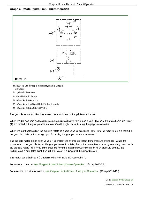
Grapple Rotate Hydraulic Circuit Operation...872
Main Hydraulic Pump and Pressure Compensator Operation...873
Brake Accumulator Operation...876
Hydraulic Reservoir Operation...877
Hydraulic Oil Return Filter Operation...879
Hydraulic Fan Filter Operation...881
Brake Valve Operation...882
Priority Valve Operation...885
Steering Valve and System Operation...889
Secondary Steering Inlet Manifold Operation...891
120 Series Cylinder Operation...893
Blade Manually Operated Valve Section Operation...895
Arch Manually Operated Valve Section Operation...897
Arch Pilot Operated Valve Section Operation...898
System Relief Valve Operation...899
Circuit Relief Valve—Adjustable With Anticavitation Operation...901
Circuit Relief Valve—Non-Adjustable Operation...903
Grapple Tong Manually Operated Valve Section Operation...904
Grapple Tong Flow Divider Operation...906
Pilot Controller Operation...908
Grapple Rotate Solenoid Valve Operation...909
Dual Mode Steering Solenoid Valve Operation...911
Rotary Manifold Operation...913
Fan Pump Operation...914
Fan Variable Speed and Reversing Manifold Operation...917
Reversing Fan Motor Operation...919
Hydraulic Oil Cooler Operation...920
Cab Tilt Circuit Operation...921
Group 15: Diagnostic Information...850
Hydraulic System Overheating...850
Hydraulic Function Drifts Down...850
No Steering or Hydraulic Functions...850
Hydraulic Functions Slow...850
Individual Functions Slow (Cycle Time Slow)...850
No Hydraulic Functions (Steering Normal)...850
Low Hydraulic Power (Pressure)...850
Excessive Hydraulic Pump Noise...850
Function Powers Up or Down Without Moving Lever...850
Grapple Rotate Stalls...850
Grapple Rotates Too Fast...850
Grapple Rotates Slow...850
Tongs Do Not Close Evenly...850
Tongs Open or Close Slowly...850
Grapple Loses Logs During Skidding...850
Transmission Overfills With Oil...850
No Steering (Hydraulic Functions Normal)...850
Steering Valve Does Not Center...850
Steering Valve Locks Up...850
Frames Turn Wrong Direction...850
Steering Slow or Hard...850
Steering Erratic or Spongy...850
Machine Wanders...850
Quick Steer Mode Not Engaging...850
Quick Steer Mode Not Disengaging...850
Quick Steer Mode Engaging When Disengaged...850
Poor or No Brakes (Other Hydraulic Systems Normal)...850
Brakes Overly Aggressive...851
Brakes Drag...851
Brakes Chatter or Noisy...851
Delay in Braking...851
Fan Does Not Reach Full Speed (Both Directions)...851
Fan Does Not Reach Full Speed (Forward Direction Only)...851
Fan Does Not Reach Full Speed (Reverse Direction Only)...851
Fan Does Not Spin (Both Directions)...851
Fan Does Not Slow Down Before Reversing...851
High Cooler Pressure or Pressure Spikes...851
High Return Pressure at Fan Reversing Manifold Port T...851
High Flow From Fan Motor Case Drain...851
Fan Pump is Cavitating...851
Hydraulic System Component Location...999
Hydraulic System Schematic...1003
Group 20: Adjustments...851
Service Brake Pedal Adjustment...1009
Service Brake Inspection and Adjustment...1010
Service Brake Bleeding Procedure...1011
Grapple Dampener Adjustment...1015
Group 25: Test...851
D15032NU Vacuum Pump Installation...1019
JT02156A Digital Pressure and Temperature Analyzer Installation...1020
JT07148 Digital Hydraulic Tester...1022
Hydraulic Oil Warmup Procedure...1023
Main Hydraulic Pump Identification...1024
Main Hydraulic Pump Standby Pressure Test...1025
Main Hydraulic Pump Flow Test...1028
Main Hydraulic Pump Leakage Test...1031
Pressure Reducing Valve Pressure Test...1033
Pilot Controller Pressure Test...1035
Priority Valve and Relief Valve Pressure Test...1038
Priority Valve “LS” Port Flow Test...1041
Priority Valve and Relief Valve Leakage Test...1043
System and Circuit Relief Valve Pressure Test...1045
Hydraulic Component Leakage Test...1050
Cylinder Leakage Test...1054
Cylinder Drift Test...1057
Dual Mode Steering Engagement Pressure Test...1059
Grapple Rotate Motor Crossover Relief Valve Pressure Test...1062
Grapple Rotate Solenoid Valve Neutral Leakage Test...1064
Grapple Tong Flow Divider Relief Valve Test...1066
Rotary Manifold Center Seal Leakage Test...1068
Rotary Manifold Drain and Lower Seal Leakage Test...1070
Service Brake Valve and Accumulator Pressure Test...1072
Service Brake Valve Leakage Test...1075
Steering Valve Neutral Leakage Test...1078
Hydraulic Functions Cycle Time Test...1080
Hydraulic Oil Filter Inspection Procedure...1082
Cooling Fan Circuit Test Procedure...1083
Fan Motor Case Drain Test...1088
Secondary Steering Operation Test...1090
Section 9030: Winch...1093
Group 05: Theory of Operation...1093
John Deere 4000 Winch...1095
Group 15: Diagnostic Information...1093
Winch Control Lever Effort Excessive...1093
Winch Clutch Slips...1093
Winch Free Spool Effort Excessive...1093
Winch Brake Will Not Hold...1093
Winch Will Not Free Spool...1093
Transmission Oil Level Varies Excessively...1093
Winch Makes Grinding Noise When Going from FREE SPOOL to BRAKE OFF...1093
Winch Component Location...1111
Winch Hydraulic Schematic...1112
Group 20: Adjustments...1093
Winch Control Cable Adjustment Check...1114
Brake Off Adjustment...1115
Group 25: Test...1093
Winch System Pressure Test...1124
Winch Leakage Test...1128
Winch Drum Rolling Drag Test...1132
Section 9031: Heating and Air Conditioning...1134
Group 05: Theory of Operation...1134
Air Conditioning System Cycle of Operation...1137
Group 15: Diagnostic Information...1134
Air Conditioning System Visual Checks...1143
Blower Does Not Operate In Any Speed...1134
Blower Does Not Operate In Low Speed...1134
Blower Does Not Operate In Medium Speed...1134
Blower Does Not Operate In High Speed...1134
Blower Does Not Operate In Purge Speed...1134
Air Conditioner Does Not Operate...1134
Air Conditioner Does Not Cool Cab Interior...1134
Air Conditioner Runs Constantly...1134
Interior Windows Continuously Foggy...1134
Heater Does Not Operate...1134
Heater Does Not Warm Cab Interior...1134
Heating and Air Conditioning System Component Location...1178
Group 25: Tests...1134
R134a Air Conditioning System Test...1184
Air Conditioner Freeze Control Switch Test...1188
Air Conditioning Compressor Clutch Test...1190
Air Conditioning High/Low Pressure Switch Test...1191
Air Conditioning Expansion Valve Test...1193
Refrigerant Leak Test...1196
John Deere 540H and 548H Skidder ( —630435) Technical Manual (TM11329)


