John Deere 130G Excavator Technical Manual - Operation & Test (TM12348)
Catalog:
Model:
Complete Operation and Test Manual with Electrical Wiring Diagrams for John Deere 130G (iT4/S3B) Excavator (S.N.1FF130GX_E040001), with all the technical information to maintain, diagnose, and rebuild like professional mechanics.
John Deere Excavator 130G workshop Diagnostics and Test manual includes:
* Numbered table of contents easy to use so that you can find the information you need fast.
* Detailed sub-steps expand on repair procedure information
* Numbered instructions guide you through every repair procedure step by step.
* Troubleshooting and electrical service procedures are combined with detailed wiring diagrams for ease of use.
* Notes, cautions and warnings throughout each chapter pinpoint critical information.
* Bold figure number help you quickly match illustrations with instructions.
* Detailed illustrations, drawings and photos guide you through every procedure.
* Enlarged inset helps you identify and examine parts in detail.
TM12348 - John Deere130G Excavator Operation & Test Service Manual.pdf
tm12349 - John Deere Excavatrice 130G.pdf
tm12350 - John Deere Excavadora 130G.pdf
Total Pages: 1,356 pages
File Format: PDF (bookmarked, ToC, Searchable, Printable)
Category: Operation and Test
Language: English Spanish French
Models: John Deere - Excavator - 1FF130G___E040001 (iT4/S3B)
Published on 2019/12/30
MAIN SECTIONS
Foreword
Technical Information Feedback Form
General Information
Safety
Diagnostics
Main Controller (MCZ) Diagnostic Trouble Codes
Engine Control Unit (ECU) Diagnostic Trouble Codes
Monitor Controller (DSZ) Diagnostic Trouble Codes
Air Conditioner Controller (ACF) Diagnostic Trouble Codes
Operational Checkout Procedure
Operational Checkout Procedure
Engine
Theory of Operation
Diagnostic Information
Adjustments
Tests
Electrical System
System Information
System Diagrams
Sub-System Diagnostics
Monitor Operation
References
Power Train
Theory of Operation
Diagnostic Information
Hydraulic System
Theory of Operation
Diagnostic Information
Tests
Heating and Air Conditioning
Theory of Operation
Diagnostic Information
Tests
Dealer Fabricated Tools
TABLE OF CONTENTS
Section 9000: General Information...22
Group 01: Safety...22
Recognize Safety Information...25
Follow Safety Instructions...26
Operate Only If Qualified...27
Wear Protective Equipment...28
Avoid Unauthorized Machine Modifications...29
Control Pattern Selector—If Equipped...30
Add Cab Guarding for Special Uses...31
Inspect Machine...32
Stay Clear of Moving Parts...33
Avoid High-Pressure Fluids...34
Avoid High-Pressure Oils...35
Work In Ventilated Area...36
Prevent Fires...37
Prevent Battery Explosions...38
Handle Chemical Products Safely...39
Decommissioning — Proper Recycling and Disposal of Fluids and Components...40
Exhaust Filter Ash Handling and Disposal...41
Prepare for Emergencies...42
Clean Debris from Machine...43
Use Steps and Handholds Correctly...44
Start Only From Operator's Seat...45
Use and Maintain Seat Belt...46
Prevent Unintended Machine Movement...47
Avoid Work Site Hazards...48
Keep Riders Off Machine...50
Avoid Backover Accidents...51
Inspect and Maintain ROPS...52
Avoid Machine Tip Over...53
Use Special Care When Lifting Objects...55
Add and Operate Attachments Safely...56
Park and Prepare for Service Safely...57
Service Cooling System Safely...58
Remove Paint Before Welding or Heating...59
Make Welding Repairs Safely...60
Drive Metal Pins Safely...61
Clean Exhaust Filter Safely...62
Section 9001: Diagnostics...65
Group 10: Main Controller (MCZ) Diagnostic Trouble Codes...71
Main Controller (MCZ) Diagnostic Trouble Codes...71
Controller Area Network 0 (CAN 0) Circuit Diagnostics...72
Controller Area Network 1 (CAN 1) Circuit Diagnostics...89
Interface Controller Area Network (N-CAN) Diagnostics...107
Engine Controller Area Network (Engine CAN) Diagnostics...117
011000.02 - Abnormal EEPROM...65
011001.02 - Abnormal RAM...65
011002.02 - Abnormal A/D Converter...65
011003.03 - Abnormal Sensor Voltage...65
011006.02 - Engine Controller Communication Error...65
011007.02 - (CAN 0) Data Converter Communication Error 1...65
011008.02 - (CAN 1) Data Converter Communication Error 2...65
011009.02 - (CAN 0) Monitor Controller Communication Error 1...65
011010.02 - (CAN 1) Monitor Controller Communication Error 2...65
011100.02 - Abnormal Engine Speed...65
011101.03 - Engine Control Dial Sensor Circuit High Input...65
011101.04 - Engine Control Dial Sensor Circuit Low Input...65
011200.03 - Pump 1 Delivery Pressure Sensor Circuit High Input...65
011200.04 - Pump 1 Delivery Pressure Sensor Circuit Low Input...65
011202.03 - Pump 2 Delivery Pressure Sensor Circuit High Input...65
011202.04 - Pump 2 Delivery Pressure Sensor Circuit Low Input...65
011206.03 - Pump 1 Flow Control Pressure Sensor Circuit High Input...65
011206.04 - Pump 1 Flow Control Pressure Sensor Circuit Low Input...65
011208.03 - Pump 2 Flow Control Pressure Sensor Circuit High Input...65
011208.04 - Pump 2 Flow Control Pressure Sensor Circuit Low Input...65
011301.03 - Swing Pilot Pressure Sensor Circuit High Input...65
011301.04 - Swing Pilot Pressure Sensor Circuit Low Input...65
011302.03 - Boom Up Pilot Pressure Sensor Circuit High Input...65
011302.04 - Boom Up Pilot Pressure Sensor Circuit Low Input...65
011303.03 - Arm In Pilot Pressure Sensor Circuit High Input...65
011303.04 - Arm In Pilot Pressure Sensor Circuit Low Input...65
011304.03 - Travel Pilot Pressure Sensor Circuit High Input...66
011304.04 - Travel Pilot Pressure Sensor Circuit Low Input...66
011307.03 - Front Attachment Pilot Pressure Sensor Circuit High Input...66
011307.04 - Front Attachment Pilot Pressure Sensor Circuit Low Input...66
011400.02 - Pump 2 Flow Rate Limit Solenoid Valve Abnormal Feedback...66
011400.03 - Pump 2 Flow Rate Limit Solenoid Valve Feedback High Current...66
011400.04 - Pump 2 Flow Rate Limit Solenoid Valve Feedback Low Current...66
011401.02 - Torque Control Solenoid Valve Abnormal Feedback...66
011401.03 - Torque Control Solenoid Valve Feedback High Current...66
011401.04 - Torque Control Solenoid Valve Feedback Low Current...66
011402.02 - 4-Spool Solenoid Valve Unit (SF) Abnormal Feedback...66
011402.03 - 4-Spool Solenoid Valve Unit (SF) Feedback High Input...66
011402.04 - 4-Spool Solenoid Valve Unit (SF) Feedback Low Input...66
011403.02 - 4-Spool Solenoid Valve Unit (SC) Abnormal Feedback...66
011403.03 - 4-Spool Solenoid Valve Unit (SC) Feedback High Input...66
011403.04 - 4-Spool Solenoid Valve Unit (SC) Feedback Low Input...66
011407.02 - 4-Spool Solenoid Valve Unit (SG) Abnormal Feedback...66
011407.03 - 4-Spool Solenoid Valve Unit (SG) Feedback High Input...66
011407.04 - 4-Spool Solenoid Valve Unit (SG) Feedback Low Input...66
011408.02 - 2-Spool Solenoid Valve Unit (SJ) Abnormal Feedback...66
011408.03 - 2-Spool Solenoid Valve Unit (SJ) Feedback High Input...66
011408.04 - 2-Spool Solenoid Valve Unit (SJ) Feedback Low Input...66
011409.02 - 2-Spool Solenoid Valve Unit (SZ) Abnormal Feedback...66
011409.03 - 2-Spool Solenoid Valve Unit (SZ) Feedback High Input...66
011409.04 - 2-Spool Solenoid Valve Unit (SZ) Feedback Low Input...66
011428.02 - 4-Spool Solenoid Valve Unit (SD) Abnormal Feedback...66
011428.03 - 4-Spool Solenoid Valve Unit (SD) Feedback High Input...66
011428.04 - 4-Spool Solenoid Valve Unit (SD) Feedback Low Input...66
011434.02 - Attachment Relief 1 (Upper) Proportional Solenoid Valve Abnormal Feedback...66
011434.03 - Attachment Relief 1 (Upper) Proportional Solenoid Valve Feedback High Current...66
011434.04 - Attachment Relief 1 (Upper) Proportional Solenoid Valve Feedback Low Current...66
011435.02 - Attachment Relief 2 (Lower) Proportional Solenoid Valve Abnormal Feedback...66
011435.03 - Attachment Relief 2 (Lower) Proportional Solenoid Valve Feedback High Current...66
011435.04 - Attachment Relief 2 (Lower) Proportional Solenoid Valve Feedback Low Current...67
011436.02 - Breaker Relief Proportional Solenoid Valve Abnormal Feedback...67
011436.03 - Breaker Relief Proportional Solenoid Valve Feedback High Current...67
011436.04 - Breaker Relief Proportional Solenoid Valve Feedback Low Current...67
011457.02 - 2-Speed Activation Solenoid Disconnected or Not Present...67
011458.02 - Selector Valve Solenoid Valve Disconnected or Not Present...67
011459.02 - Idle Stop Relay Circuit Malfunction...67
011810.03 - Electrical Lever Control Pressure 1 Sensor High Input...67
011810.04 - Electrical Lever Control Pressure 1 Sensor Low Input...67
011901.03 - Hydraulic Oil Temperature Sensor Circuit High Input...67
011901.04 - Hydraulic Oil Temperature Sensor Circuit Low Input...67
020010.02 - Abnormal Exhaust Filter...67
020012.02 - Line Filter Restriction Alarm...67
Group 20: Engine Control Unit (ECU) Diagnostic Trouble Codes...316
Engine Control Unit (ECU) Diagnostic Trouble Codes...316
000111.07 - Coolant Level Low—Moderately Severe Level...67
000111.17 - Coolant Level Low—Most Severe Level...67
000158.01 - Battery Voltage Low...67
000647.05 - Variable Speed Fan Solenoid Open Circuit...67
000647.06 - Variable Speed Fan Solenoid Short Circuit...67
000647.16 - Reversing Fan Switch Active Too Long...67
000676.05 - Glow Plug Relay Low Current...67
000676.06 - Glow Plug Relay High Current...67
000676.14 - Glow Plug Relay Output Low When Relay Active...67
000676.31 - Glow Plug Relay Output High When Relay Not Active...67
000898.09 - Requested Speed/Speed Limit...67
001638.09 - Hydraulic Temperature...67
001639.00 - Fan Speed High—Most Severe Level...67
001639.01 - Fan Speed Low—Most Severe Level...67
001639.18 - Fan Speed Low—Moderately Severe Level...67
003701.14 - Exhaust Filter Cleaning Not Required...67
005484.05 - Reversing Fan Solenoid Open Circuit...67
005484.06 - Reversing Fan Solenoid Short Circuit...67
Group 30: Monitor Controller (DSZ) Diagnostic Trouble Codes...351
Monitor Controller (DSZ) Diagnostic Trouble Codes...351
013002.02 - ECU Communication Error...68
013003.02 - Main Controller (MCZ) Communication Error 1...68
013004.02 - Main Controller (MCZ) Communication Error 2...68
013005.02 - Monitor Controller (DSZ) Communication Error 1...68
013006.02 - Monitor Controller (DSZ) Communication Error 2...68
013007.02 - Machine Controller (BCZ) Communication Error...68
020113.02 - System Error Alarm...68
Group 40: Information Controller (ICZ) Diagnostic Trouble Codes...360
Information Controller (ICZ) Diagnostic Trouble Codes...360
013303.02 - Abnormal Monitor Internal Temperature Sensor...68
013304.02 - Alternator Alarm...68
013310.03 - Shorted Circuit in Coolant Temperature Sensor...68
013311.03 - Fuel Level Sensor Open Circuit...68
013311.04 - Fuel Level Sensor Shorted Circuit...68
013334.02 - Radiator Coolant Error...68
014001.02 - Flash Memory Read/Write Error...68
014002.02 - External RAM Read/Write Error...68
014003.02 - Abnormal EEPROM...68
014006.02 - Communication Terminal:Communication Error...68
014008.02 - Abnormal Internal RAM...68
014021.02 - Communication Terminal Security Error...68
014022.02 - SIM Card Error...68
014023.02 - Security Error...68
020100.02 - Overheat Alarm...68
020101.02 - Engine Warning Alarm...68
020102.02 - Engine Oil Pressure Alarm...68
020105.02 - Hydraulic Oil Filter Restriction Alarm...68
020106.02 - Air Cleaner Restriction Alarm...68
020107.02 - Water Separator Alarm...68
020109.02 - Pilot Control Shut-Off Lever Alarm...68
020110.02 - Fuel Filter Restriction Alarm...68
020114.02 - Overheat Alarm...69
020133.02 - Crane Function Alarm...69
020137.02 - Exhaust Filter Alarm...69
020141.02 - Exhaust Temperature Alarm...69
020142.02 - Intake Air Temperature Alarm...69
020145.02 - Boost Temperature Increase Alarm...69
020146.02 - Fuel Temperature Increase Alarm...69
020149.02 - EGR Gas Temperature Alarm...69
Group 50: Air Conditioner Controller (ACF) Diagnostic Trouble Codes...399
Air Conditioner Controller (ACF) Diagnostic Trouble Codes...399
11 - Open Circuit in Air Recirculation Sensor...69
12 - Short-Circuited Air Recirculation Sensor...69
13 - Open Circuit in Ambient Air Temperature Sensor...69
14 - Short-Circuited Ambient Air Temperature Sensor...69
18 - Short-Circuited Solar Radiation Sensor...69
21 - Open Circuit in Air Conditioner Freeze Control Switch...69
22 - Short-Circuited Air Conditioner Freeze Control Switch...69
43 - Abnormal Air Conditioner and Heater Blower Port Change Servomotor...69
44 - Abnormal Air Conditioner and Heater Mixer Servomotor...69
91 - Communication Error...69
92 - CAN Bus Off Error...69
Section 9005: Operational Checkout Procedure...426
Group 10: Operational Checkout Procedure...426
Operational Checkout...495
Section 9010: Engine...563
Group 05: Theory of Operation...848
Engine Identification...567
John Deere Engine...587
Engine Fuel System Component Location...571
Engine Cooling System Component Location...572
Cold Weather Starting Aid...573
Engine Speed Control System Operation...848
Group 15: Diagnostic Information...563
John Deere Engine...587
Group 20: Adjustments...563
John Deere Engine...587
Group 25: Tests...563
John Deere Engine...587
Radiator Temperature Differential Check...588
Section 9015: Electrical System...591
Group 05: System Information...591
Electrical Diagram Information...604
Group 10: System Diagrams...591
Explanation of Wire Markings...613
Fuse and Relay Specifications...614
System Functional Schematic, Component Location, and Wiring Diagram Master Legend...623
System Functional Schematic...632
Cab Harness (W1) Component Location...653
Cab Harness (W1) Wiring Diagram...660
Machine Harness (W2) Component Location...669
Machine Harness (W2) Wiring Diagram...673
Monitor Harness (W3) Component Location...675
Monitor Harness (W3) Wiring Diagram...676
Engine Harness (W4) Component Location...678
Engine Harness (W4) Wiring Diagram...681
Engine Interface Harness (W5) Component Location...684
Engine Interface Harness (W5) Wiring Diagram...686
Pump Harness (W8) Component Location...688
Pump Harness (W8) Wiring Diagram...690
Exhaust Filter Parked Cleaning Switch Harness (W9) Component Location...692
Exhaust Filter Parked Cleaning Switch Harness (W9) Wiring Diagram...693
Service ADVISOR™ Remote (SAR) Harness (W10) Component Location...694
Service ADVISOR™ Remote (SAR) Switch Harness (W10) Wiring Diagram...695
Pilot Shutoff Switch Harness (W11) Component Location...697
Pilot Shutoff Switch Harness (W11) Wiring Diagram...698
Service ADVISOR™ Remote (SAR) Switch Resistor Harness (W12) Component Location...699
Service ADVISOR™ Remote (SAR) Switch Resistor Harness (W12) Wiring Diagram (S.N. 040755— )...700
Auxiliary Fuse Box Harness (W13) Component Location...701
Auxiliary Fuse Box Harness (W13) Wiring Diagram...702
Heated Air Seat Harness (W14) Component Location...704
Heated Air Seat Harness (W14) Wiring Diagram...706
Multi-Function Pilot Control Lever Harness (W15) Component Location...707
Multi-Function Pilot Control Lever Harness (W15) Wiring Diagram...709
Travel Alarm Cancel Switch Harness (W16) Component Location...710
Travel Alarm Cancel Switch Harness (W16) Wiring Diagram...711
Attachment Harness (W17) Component Location...712
Attachment Harness (W17) Wiring Diagram...714
Rear Camera Harness (W19) Component Location...715
Rear Camera Harness (W19) Wiring Diagram...716
Pilot Shutoff Valve Harness (W21) Component Location...717
Pilot Shutoff Valve Harness (W21) Wiring Diagram...718
Auxiliary 3-Button Cancel Switch Harness (W22) Component Location...719
Auxiliary 3-Button Cancel Switch Harness (W22) Wiring Diagram...720
Reversing Fan Switch Harness (W23) Component Location...721
Reversing Fan Switch Harness (W23) Wiring Diagram...722
Seat Heater Switch Harness (W24) Component Location...723
Seat Heater Switch Harness (W24) Wiring Diagram...724
Travel Alarm Harness (W26) Component Location...725
Travel Alarm Harness (W26) Wiring Diagram...726
Starter Harness (W27) Component Location...727
Starter Harness (W27) Wiring Diagram...728
Starter Switch Harness (W29) Component Location...730
Starter Switch Harness (W29) Wiring Diagram...731
2-Speed Harness (W32) Component Location...592
2-Speed Harness (W32) Wiring Diagram...592
Fuel Injector Harness (W38) Component Location...734
Fuel Injector Harness (W38) Wiring Diagram...735
Glow Plug Harness (W40) Component Location...736
Glow Plug Harness (W40) Wiring Diagram...738
Heater and Air Conditioner Harness (W41) Component Location...739
Heater and Air Conditioner Harness (W41) Wiring Diagram...740
Heater and Air Conditioner Relay Harness (W51) Component Location...741
Heater and Air Conditioner Relay Harness (W51) Wiring Diagram...742
Auxiliary Solenoid Harness (W61) Component Location...744
Auxiliary Solenoid Harness (W61) Wiring Diagram...746
Satellite (SAT) Harness (W6003) Component Location...748
Satellite (SAT) Harness (W6003) Wiring Diagram...749
Group 15: Sub-System Diagnostics...593
Controller Area Network (CAN) Theory of Operation...848
Starting and Charging Circuit Theory of Operation...848
Monitor Controller (DSZ) Circuit Theory of Operation...848
Engine Control Unit (ECU) Circuit Theory of Operation...848
Exhaust Aftertreatment Circuit Theory of Operation...848
Main Controller (MCZ) Circuit Theory of Operation...848
Travel Alarm Circuit Theory of Operation...848
Machine Controller (BCZ) Circuit Theory of Operation...848
Windshield Wiper and Washer Circuit Theory of Operation...848
Lighting Circuit Theory of Operation...848
Pilot Shutoff Circuit Theory of Operation...848
Attachment Control Circuit Theory of Operation...848
Group 16: Monitor Operation...848
Service Menu...837
Troubleshooting...838
Monitoring...839
Controller Version...846
Issued Warning Record...847
Operation...848
Machine Setting...849
Monitor Setting...856
Exhaust Filter No...859
Group 20: References...593
Reading Diagnostic Trouble Codes with Monitor Display...861
Service ADVISOR™ Diagnostic Application...862
Service ADVISOR™ Connection Procedure...863
Reading Diagnostic Trouble Codes with Service ADVISOR™ Diagnostic Application...866
MPDr Application...869
MPDr Connection Procedure...870
Fuse Test...872
Relay Test...882
Pressure Sensor Test...883
Solenoid Test...886
Proportional Solenoid Test...887
Temperature Sensor Test...888
Alternator Test...890
Controller Area Network (CAN) Circuit Test...892
Electrical Component Checks...896
Battery Remove and Install...905
Rear Cover Remove and Install...907
Main Controller (MCZ) Remove and Install...909
Machine Controller (BCZ) Remove and Install...912
Engine Control Unit (ECU) Remove and Install...915
Data Converter Remove and Install...917
Monitor Controller (DSZ) Remove and Install...918
Air Conditioner Controller (ACF) Remove and Install...920
Key Switch Remove and Install...921
Right Switch Console Remove and Install...922
Left Switch Console Remove and Install...924
Travel Alarm Remove and Install...926
Heater Control Disable and Enable...927
Disconnect Tab Retainer Connectors...928
Disconnecting Spring Wire Clip Connectors...929
Replace DEUTSCH™ Connectors...930
Replace DEUTSCH™ Rectangular or Triangular Connectors...932
Install DEUTSCH™ Contact...934
Replace WEATHER PACK™ Connector...936
Install WEATHER PACK™ Contact...938
Replace (Pull Type) Metri-Pack™ Connectors...940
Replace (Push Type) Metri-Pack™ Connectors...942
Replace CINCH™ Connectors...943
Install CINCH™ Contact...945
Repair 32 and 48 Way CINCH™ Connectors...947
Remove Connector Body from Blade Terminals...951
Section 9020: Power Train...952
Group 05: Theory of Operation...848
Track Adjuster and Recoil Spring Operation...955
Travel Gear Case Operation...957
Group 15: Diagnostic Information...952
Noisy or Loose Track Chain...952
Tight Track Chain...952
Frequent Track Chain Sag Adjustment Required...952
Excessive Oil Leakage From Front Idler, Track Rollers, or Carrier Rollers...952
Bent Track Shoes...952
Section 9025: Hydraulic System...979
Group 05: Theory of Operation...848
Hydraulic System Operation...984
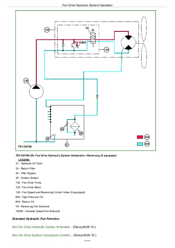
Fan Drive Hydraulic System Operation...985
Pilot System Operation...989
Pilot Pump, Pressure Regulating Valve, and Filter Operation...990
Pilot Shutoff Solenoid Valve Operation...992
Pilot Control Valve Operation...1027
Travel Pilot Control Valve Operation...1027
Pilot Operation of Control Valve Operation...1027
Pilot Signal Manifold Operation...1005
Pump 1, Pump 2, and Drive Gear Case Operation...1014
Pump 1 and Pump 2 Regulator Operation...1017
Engine Speed Sensing Control Circuit Operation...1025
Control Valve Operation...1027
Control Valve Check Valves Identification and Operation...1039
Main Relief Valve Circuit Operation...1043
Circuit Relief and Anticavitation Valve Operation...1047
Travel Flow Combiner Valve Operation...1049
Auxiliary Flow Combiner Valve and Bypass Shutoff Valve Operation...1052
Boom Lower Meter-In Cut Valve Operation...1057
Boom Regenerative Valve Circuit Operation...1060
Dig Regenerative Valve Circuit Operation...1062
Arm Regenerative Valve Circuit Operation...1067
Bucket Regenerative Valve Circuit Operation...1073
Boom and Arm Reduced Leakage Valves Operation...1075
Arm 1 Flow Rate Control Valve Circuit Operation...1078
Arm 2 Flow Rate Control Valve Circuit Operation...1083
Bucket Flow Rate Control Valve Circuit Operation...1088
Boom Flow Rate Control Valve Circuit Operation...1094
Auxiliary Flow Rate Control Valve Circuit Operation...1099
Blade Circuit Operation—If Equipped...1105
Swing Reduction Gear Case Operation...1107
Swing Motor, Crossover Relief Valve, and Make-Up Check Valve Operation...1108
Swing Motor Park Brake Release Circuit Operation...1111
Center Joint Operation...1113
Travel Motor and Park Brake Valve Operation...1115
Travel Motor Speed Circuit Operation...1122
Cylinder Operation...1126
Return Filter Operation...1128
Auxiliary System Operation...1129
Auxiliary Pilot Control Valve Operation...1130
Flow Rate Select Solenoid Valve Operation...1135
Flow Rate Pressure Reducing Valve Operation...1137
Selector Valve Solenoid Valve Operation...1138
Selector Valve Operation...1139
Auxiliary Shuttle Valve Operation...1140
Auxiliary High Flow Line Kit Operation...1142
Two Way Solenoid Kit Operation...1146
Two Pump Combined Flow Kit Operation...1149
Group 15: Diagnostic Information...980
All Hydraulic Functions Slow...980
Hydraulic Oil Overheats...980
No Hydraulic Functions...980
Poor Combined Operation...848
All Functions Cannot Be Operated...980
Function Does Not Stop When Control Lever Released...980
Some Functions Cannot Be Operated, All Others Are Normal...980
All Functions Slow...980
Functions Move in Opposite Direction...980
All Dig Functions Slow or No Power...980
Some Dig Functions Slow (Not All)...980
Load Drifts Down When Control Lever is in Neutral Position...980
Load Falls When Control Valve is Actuated To Raise Load With Engine Running at Slow Idle...980
H/P (High Power) Function Does Not Operate, PWR (Power) Mode is Normal...980
Swing Speed Slow in Both Directions...980
Swing Speed Slow or Does Not Operate in One Direction...981
Upperstructure Drift with Swing Valve in Neutral...981
Swing Function Does Not Operate...981
Travel Park Brakes Do Not Apply...981
Track Will Not Move in One Direction...981
Track Will Not Move in Either Direction...981
Machine Mistracks at All Speeds in Both Directions...981
Slow Travel Speed or Low Power...981
Combined Travel and Dig Functions Slow or No Power...981
Travel is “Jerky”...981
Machine Will Not Hold Back and Park Brakes Engage and Disengage When Traveling Down an Incline...981
Machine Will Not Turn Smoothly in One Direction or Park Brake Grabs...981
Pump 1, Pump 2, and Pilot Pump Line Identification...1220
Control Valve Line Identification...1222
Swing Motor Line Identification...1225
Pilot Control Valve-to-Pilot Signal Manifold Component Location—Excavator Pattern...1226
Pilot Control Valve-to-Pilot Signal Manifold Component Location—Backhoe Pattern...1228
Pilot Signal Manifold-to-Control Valve Line Connection...1230
Travel System Component Location...1233
Travel Hydraulic System Line Connection...1235
Blade Hydraulic System Component Location...1258
Auxiliary Attachment Schematic...1239
Auxiliary System Line Connections...1244
Hydraulic System Schematic...1246
Hydraulic System Component Location...1258
Hydraulic System Line Connections...1260
Fan Drive System Component Location...1261
Fan Drive Hydraulic System Schematic...1262
Group 25: Tests...981
JT05800 Digital Thermometer Installation...1265
JT02156A Digital Pressure and Temperature Analyzer Kit Installation...1266
Hydraulic Oil Cleanup Procedure...1267
Hydraulic Oil Tank Pressure Release Procedure...1270
Hydraulic Oil Warm-Up Procedure...1271
Pilot Pressure Regulating Valve Test and Adjustment...1274
Control Valve Spool Actuating Pilot Pressure Test...1278
Dig Regenerative Solenoid Valve Test and Adjustment...1281
Arm Regenerative Solenoid Valve Test and Adjustment...1286
Power Dig/Travel Speed Solenoid Valve Test and Adjustment...1291
Arm 2 Flow Control Solenoid Valve Test and Adjustment...1296
Torque Control Solenoid Valve Test and Adjustment...1301
Pump Control Pilot Pressure Signal Test...1306
Main Relief and Power Dig Valve Test and Adjustment...1309
Circuit Relief Valve Test and Adjustment...1316
Blade Main Relief Valve Test and Adjustment...1322
Swing Motor Crossover Relief Valve Test and Adjustment...1327
Travel Motor Crossover Relief Valve Test and Adjustment...1331
Pump Regulator Test and Adjustment—Minimum Flow...1337
Pump Regulator Test and Adjustment—Maximum Flow...1340
Pump Flow Test...1343
Comprehensive Pump Flow Test...1347
Swing Motor Leakage Test...1353
Travel Motor Leakage Test...1356
Cylinder Drift Test—Boom, Arm, and Bucket...1360
Fan Drive Pump Flow Test...1363
Fan Speed Test...1366
Section 9031: Heating and Air Conditioning...1369
Group 05: Theory of Operation...848
Air Conditioning System Cycle of Operation...1372
Group 15: Diagnostic Information...1369
Air Conditioning System Does Not Operate...1369
No Air Flow From Heater and Air Conditioner Vents...1369
Air Conditioning Does Not Cool Interior of Cab...1369
Air Conditioning Runs Constantly, Too Cold...1369
Interior Windows Continue to Fog Using Air Conditioner...1369
Heater System Does Not Operate...1369
Heater Does Not Warm Interior of Cab...1369
Interior Windows Continue to Fog Using Heater...1369
Heater and Air Conditioner Component Location...1407
Group 25: Tests...1369
Refrigerant Cautions and Proper Handling...1410
Heater and Air Conditioner Operational Checks...1411
Air Conditioner Compressor Clutch Test...1414
Refrigerant Leak Test...1415
Refrigerant Hoses and Tubing Inspection...1416
Air Conditioner Compressor Belt Check...1417
Air Conditioner High/Low-Pressure Switch Test...1418
Air Conditioner Freeze Control Switch Test...1421
R134a Air Conditioning System Test...1422
Operating Pressure Diagnostic Chart...1425
Section 9900: Dealer Fabricated Tools...1426
Group 99: Dealer Fabricated Tools...1426
DFT1218 Split Flange Hose Cap...1428
John Deere 130G Excavator Technical Manual - Operation & Test (TM12348)


