John Deere E330LC Excavator Operation and Test Service Manual (TM13103X19)
Catalog:
Model:
Complete Operation and Test manual with electrical wiring diagrams for John Deere E330LC Excavator (PIN: 1YNE33AL_ _C600002-; 1YNE33AL_ _D600025-), with all the workshop information to maintain, diagnose, and rebuild like professional mechanics.
John Deere E330LC Excavator workshop Operation and Test manual includes:
* Numbered table of contents easy to use so that you can find the information you need fast.
* Detailed sub-steps expand on repair procedure information
* Numbered instructions guide you through every repair procedure step by step.
* Troubleshooting and electrical service procedures are combined with detailed wiring diagrams for ease of use.
* Notes, cautions and warnings throughout each chapter pinpoint critical information.
* Bold figure number help you quickly match illustrations with instructions.
* Detailed illustrations, drawings and photos guide you through every procedure.
* Enlarged inset helps you identify and examine parts in detail.
TM13103X19 - John Deere E330LC Excavator Technical Manual - Operation and Test.pdf
tm13103x14 - John Deere E330LC 挖掘机.pdf
tm13103x59 - John Deere Экскаватор E330LC.pdf
PRODUCT DETAILS:
Total Pages: 2,032 pages
File Format: PDF (bookmarked, ToC, Searchable, Printable, high quality)
Category: Operation and Test
Language: English Chinese Russian
Published on 2016/01/11
Models:
John Deere - Excavator - 1YNE33AL__D600025
John Deere - Excavator - 1YNE33AL__C600002
MAIN SECTIONS
Foreword
Manual Identification-READ THIS FIRST!
General Information
Safety
Diagnostics
Engine Control Unit (ECU) Diagnostic Trouble Codes
Automatic Temperature Control (ATC) Diagnostic Trouble Codes
Primary Display Unit (PDU) Diagnostic Trouble Codes
Sealed Switch Module (SSM) Diagnostic Trouble Codes
Vehicle Control Unit (VCU) Diagnostic Trouble Codes
JDLink (JDL) Diagnostic Trouble Codes-If Equipped
Operational Checkout Procedure
Operational Checkout Procedure
Engine
Theory of Operation
Diagnostic Information
Tests
Electrical System
System Information
System Diagrams
Sub-System Diagnostics
Monitor Operation
References
Power Train
Theory of Operation
Diagnostic Information
Hydraulic System
Theory of Operation
Diagnostic Information
Adjustments
Tests
Heating and Air Conditioning
Theory of Operation
Diagnostic Information
Tests
Dealer Fabricated Tools
Table of Contents
Foreword
Manual Identification—READ THIS FIRST!
Section 9000: General Information
Group 01: Safety
Recognize Safety Information
Follow Safety Instructions
Operate Only If Qualified
Wear Protective Equipment
Avoid Unauthorized Machine Modifications
Add Cab Guarding for Special Uses
Inspect Machine
Stay Clear of Moving Parts
Avoid High-Pressure Fluids
Avoid High-Pressure Oils
Work In Ventilated Area
Prevent Fires
Prevent Battery Explosions
Handle Chemical Products Safely
Decommissioning: Proper Recycling and Disposal of Fluids and Components
Prepare for Emergencies
Use Steps and Handholds Correctly
Start Only From Operator's Seat
Use and Maintain Seat Belt
Prevent Unintended Machine Movement
Avoid Work Site Hazards
Keep Riders Off Machine
Avoid Backover Accidents
Avoid Machine Tip Over
Do Not Lift Objects
Add and Operate Attachments Safely
Park and Prepare for Service Safely
Service Cooling System Safely
Remove Paint Before Welding or Heating
Make Welding Repairs Safely
Drive Metal Pins Safely
Section 9001: Diagnostics
Group 10: Engine Control Unit (ECU) Diagnostic Trouble Codes
Engine Control Unit (ECU) Diagnostic Trouble Codes
000094.03 - Fuel Pressure
000094.04 - Fuel Pressure
000094.17 - Fuel Pressure
000107.00 - Engine Air Filter
000111.01 - Engine Coolant Level
000676.03 - Engine Intake Air Heater Relay
000676.05 - Engine Intake Air Heater Relay
001075.12 - Electronic Fuel Pump Fault
001136.00 - ECU Temperature Signal Extremely High
001136.16 - ECU Temperature Signal Moderately High
002033.09 - VCU CAN Comm
Group 20: Automatic Temperature Control (ATC) Diagnostic Trouble Codes
Automatic Temperature Control (ATC) Diagnostic Trouble Codes
000170.03 - Cab Temp Sensor
000170.04 - Cab Temp Sensor
001547.03 - AC Evaporator Temp Sensor
001547.04 - AC Evaporator Temp Sensor
521964.03 - Cab Vent Air Outlet Position Sensor
521964.04 - Cab Vent Air Outlet Position Sensor
521970.03 - AC Low Pressure Switch
521970.04 - AC Low Pressure Switch
521970.31 - AC Low Pressure Switch
523642.01 - A/C High Pressure
523642.03 - AC High Pressure Switch
523642.04 - AC High Pressure Switch
523642.10 - A/C High Pressure Switch
523642.31 - AC High Pressure Switch
524203.03 - Fresh Air Temp Sensor
524203.04 - Fresh Air Temp Sensor
Group 30: Primary Display Unit (PDU) Diagnostic Trouble Codes
Primary Display Unit (PDU) Diagnostic Trouble Codes
000609.12 - Bad Intelligent Device and Component
001386.00 - Display Temperature Above Normal
001386.01 - Display Temperature Below Normal
003599.02 - PDU Power Supply Voltage Error
521780.12 - Over Current Condition Detected on USB Circuit
523310.12 - Bad Intelligent Device and Component
523436.14 - PDU Watchdog Time Out
523438.31 - Memory Error
523651.02 - Memory Stack Overflow
523773.03 - CAN HIGH Voltage Above Normal
523773.04 - CAN HIGH Voltage Below Normal
523774.03 - CAN LOW Voltage Above Normal
523774.04 - CAN LOW Voltage Below Normal
524050.12 - Bad Intelligent Device and Component
524076.10 - Menu Select Button Stuck
524077.10 - Back Key Button Stuck
524078.10 - 2 Button Stuck
524080.10 - 1 Button Stuck
524082.10 - Information Button Stuck
524094.10 - Down Arrow Button Stuck
524095.10 - Up Arrow Button Stuck
Group 40: Sealed Switch Module (SSM) Diagnostic Trouble Codes
Sealed Switch Module (SSM) Diagnostic Trouble Codes
000629.12 - Watchdog Time-Out
002033.09 - SSM NO CAN Message
002634.04 - Ignition Relay Output Short to Ground
002634.05 - Ignition Relay Output Open Circuit
520752.04 - Button 17 Stuck
520752.09 - Button 17 No CAN
520753.04 - Button 18 Stuck
520753.09 - Button 18 No CAN
520754.04 - Button 19 Stuck
520754.09 - Button 19 No CAN
520755.04 - Button 20 Stuck
520755.09 - Button 20 No CAN
523335.04 - Button 25 Stuck
523335.09 - Button 25 No CAN
523336.04 - Button 24 Stuck
523336.09 - Button 24 No CAN
523338.04 - Button 23 Stuck
523338.09 - Button 23 No CAN
523339.04 - Button 22 Stuck
523339.09 - Button 22 No CAN
523340.04 - Button 21 Stuck
523340.09 - Button 21 No CAN
523849.04 - Button 16 Stuck
523849.09 - Button 16 No CAN
523850.04 - Button 15 Stuck
523850.09 - Button 15 No CAN
523852.04 - Button 14 Stuck
523852.09 - Button 14 No CAN
523854.04 - Button 13 Stuck
523854.09 - Button 13 No CAN
523855.04 - Button 12 Stuck
523855.09 - Button 12 No CAN
523856.04 - Button 11 Stuck
523856.09 - Button 11 No CAN
523857.04 - Button 10 Stuck
523857.09 - Button 10 No CAN
523858.04 - Button 9 Stuck
523858.09 - Button 9 No CAN
523860.04 - Button 8 Stuck
523860.09 - Button 8 No CAN
523861.04 - Button 7 Stuck
523861.09 - Button 7 No CAN
523862.04 - Button 6 Stuck
523862.09 - Button 6 No CAN
523863.04 - Button 5 Stuck
523863.09 - Button 5 No CAN
523864.04 - Button 4 Stuck
523864.09 - Button 4 No CAN
523865.04 - Button 3 Stuck
523865.09 - Button 3 No CAN
523867.04 - Button 2 Stuck
523867.09 - Button 2 No CAN
523868.04 - Button 1 Stuck
523868.09 - Button 1 No CAN
Group 50: Vehicle Control Unit (VCU) Diagnostic Trouble Codes
Vehicle Control Unit (VCU) Diagnostic Trouble Codes
000097.03 - Water-In-Fuel Sensor
000097.16 - Water-In-Fuel
000167.03 - Alternator Output
000167.04 - Alternator Output
000237.02 - Vehicle Identification Number
000629.12 - Controller Reset
000639.12 - Vehicle Controller
000639.14 - Vehicle Controller
000677.03 - Start Relay
000677.05 - Start Relay
000677.06 - Start Relay
000701.03 - Aux 1 PS Solenoid—If Equipped
000701.05 - Aux 1 PS Solenoid—If Equipped
000701.06 - Aux 1 PS Solenoid—If Equipped
000742.03 - High/Low Travel Solenoid
000742.05 - High/Low Travel Solenoid
000742.06 - High/Low Travel Solenoid
000920.03 - Monitor Alarm
000920.05 - Monitor Alarm
000977.03 - Reverse Fan Solenoid
000977.05 - Reverse Fan Solenoid
000977.06 - Reverse Fan Solenoid
001071.03 - Fan Drive Solenoid High Side
001071.05 - Fan Drive Solenoid High Side
001071.06 - Fan Drive Solenoid High Side
001071.16 - Fan Drive Solenoid Low Side
001071.17 - Fan Drive Solenoid Low Side
001071.18 - Fan Drive Solenoid Low Side
001231.12 - Communication System
001231.14 - Communication System
001638.00 - Hydraulic Oil Temp
001638.04 - Hydraulic Oil Temp Sensor
001639.08 - Fan Speed Sensor
001713.01 - Hydraulic Oil Filter
001713.03 - Hydraulic Oil Filter Restriction Switch
002025.09 - ATC CAN Comm
002038.09 - PDU CAN Comm
002251.09 - MTG CAN Comm
003509.03 - Sensor Supply 1
003509.04 - Sensor Supply 1
003510.03 - Sensor Supply 2
003510.04 - Sensor Supply 2
003511.03 - Sensor Supply 3
003511.04 - Sensor Supply 3
520452.03 - Left Propel Forward Pressure Sensor
520452.04 - Left Propel Forward Pressure Sensor
520452.20 - Left Propel Forward Pressure Sensor
520452.21 - Left Propel Forward Pressure Sensor
520452.22 - Left Propel Pressures
520453.03 - Left Propel Reverse Pressure Sensor
520453.04 - Left Propel Reverse Pressure Sensor
520453.20 - Left Propel Reverse Pressure Sensor
520453.21 - Left Propel Reverse Pressure Sensor
520459.03 - Right Propel Reverse Pressure Sensor
520459.04 - Right Propel Reverse Pressure Sensor
520459.20 - Right Propel Reverse Pressure Sensor
520459.21 - Right Propel Reverse Pressure Sensor
520464.03 - Right Propel Forward Pressure Sensor
520464.04 - Right Propel Forward Pressure Sensor
520464.20 - Right Propel Forward Pressure Sensor
520464.21 - Right Propel Forward Pressure Sensor
520464.22 - Right Propel Pressures
520465.03 - Boom Raise Pressure Sensor
520465.04 - Boom Raise Pressure Sensor
520465.20 - Boom Raise Pressure Sensor
520465.21 - Boom Raise Pressure Sensor
520465.22 - Boom Pressures
520466.03 - Boom Lower Pressure Sensor
520466.04 - Boom Lower Pressure Sensor
520466.20 - Boom Lower Pressure Sensor
520466.21 - Boom Lower Pressure Sensor
520468.03 - Bucket Curl Pressure Sensor
520468.04 - Bucket Curl Pressure Sensor
520468.20 - Bucket Curl Pressure Sensor
520468.21 - Bucket Curl Pressure Sensor
520468.22 - Bucket Pressures
520469.03 - Bucket Dump Pressure Sensor
520469.04 - Bucket Dump Pressure Sensor
520469.20 - Bucket Dump Pressure Sensor
520469.21 - Bucket Dump Pressure Sensor
520470.03 - Arm In Pressure Sensor
520470.04 - Arm In Pressure Sensor
520470.20 - Arm In Pressure Sensor
520470.21 - Arm In Pressure Sensor
520470.22 - Arm Pressures
520476.03 - Arm Out Pressure Sensor
520476.04 - Arm Out Pressure Sensor
520476.20 - Arm Out Pressure Sensor
520476.21 - Arm Out Pressure Sensor
520477.03 - Swing Left Pressure Sensor
520477.04 - Swing Left Pressure Sensor
520477.20 - Swing Left Pressure Sensor
520477.21 - Swing Left Pressure Sensor
520477.22 - Swing Pressures
520478.03 - Swing Right Pressure Sensor
520478.04 - Swing Right Pressure Sensor
520478.20 - Swing Right Pressure Sensor
520478.21 - Swing Right Pressure Sensor
520484.03 - Aux 1-Way/2-Way Solenoid
520484.05 - Aux 1 LPR Solenoid
520484.06 - Aux 1-Way/2-Way Solenoid
520485.03 - Swing Brake Solenoid
520485.05 - Swing Brake Solenoid
520485.06 - Swing Brake Solenoid
520488.03 - Quick Coupler Solenoid
520488.05 - Quick Coupler Solenoid
520488.06 - Quick Coupler Solenoid
520489.03 - Pump 2 Solenoid High Side
520489.05 - Pump 2 Solenoid High Side
520489.06 - Pump 2 Solenoid High Side
520489.16 - Pump 2 Solenoid Low Side
520489.17 - Pump 2 Solenoid Low Side
520489.18 - Pump 2 Solenoid Low Side
520496.03 - Swing Priority Solenoid
520496.05 - Swing Priority Solenoid
520496.06 - Swing Priority Solenoid
520497.03 - AUX 1 XAO Solenoid High Side
520497.05 - AUX 1 XAO Solenoid High Side
520497.06 - AUX 1 XAO Solenoid High Side
520497.16 - AUX 1 XAO Solenoid Low Side
520497.17 - AUX 1 XAO Solenoid Low Side
520497.18 - AUX 1 XAO Solenoid Low Side
520498.03 - AUX 1 XBO Solenoid High Side
520498.05 - AUX 1 XBO Solenoid High Side
520498.06 - AUX 1 XBO Solenoid High Side
520498.16 - AUX 1 XBO Solenoid Low Side
520498.17 - AUX 1 XBO Solenoid Low Side
520498.18 - AUX 1 XBO Solenoid Low Side
520499.03 - AUX 2 XAO Solenoid
520499.05 - AUX 2 XAO Solenoid
520499.06 - AUX 2 XAO Solenoid
520500.03 - AUX 2 XBO Solenoid
520500.05 - AUX 2 XBO Solenoid
520500.06 - AUX 2 XBO Solenoid
520545.03 - Pressure Boost Solenoid
520545.05 - Pressure Boost Solenoid
520545.06 - Pressure Boost Solenoid
520546.04 - Pilot Enable Switch
520547.04 - Pressure Boost Switch
520549.03 - Boom Head Pressure Sensor
520549.04 - Boom Head Pressure Sensor
521003.03 - Left Joystick Roller
521003.04 - Left Joystick Roller
522141.03 - Pump 1 Solenoid High Side
522141.05 - Pump 1 Solenoid High Side
522141.06 - Pump 1 Solenoid High Side
522141.16 - Pump 1 Solenoid Low Side
522141.17 - Pump 1 Solenoid Low Side
522141.18 - Pump 1 Solenoid Low Side
522429.03 - Pilot Enable Solenoid
522429.05 - Pilot Enable Solenoid
522429.06 - Pilot Enable Solenoid
523776.03 - Left Joystick Video Display Button
523801.03 - Right Joystick Roller
523801.04 - Right Joystick Roller
523901.04 - Front Window Switch
523916.01 - Pilot Oil Filter
523916.03 - Pilot Oil Filter Restriction Switch
523995.02 - ECU Sent and VCU Remembered Machine Model
524089.03 - Pump Pressure Sensor 1
524089.04 - Pump Pressure Sensor 1
524090.03 - Pump Pressure Sensor 2
524090.04 - Pump Pressure Sensor 2
524096.02 - Throttle Dial
Group 60: JDLink (JDL) Diagnostic Trouble Codes—If Equipped
JDLink (JDL) Diagnostic Trouble Codes
000237.11 - MTG Not Registered, Invalid PIN
000237.19 - MTG Not Registered, PIN Mismatch
000237.13 - MTG Not Registered, Missing PIN
000629.13 - MTG Not Registered, MTG Not Configured
000629.00 - CPU Capacity Exceeded
000639.09 - MTG Not Detecting CAN Bus Messages
000841.05 - GPS Antenna Error, Open Circuit
000841.06 - GPS Antenna Error, Grounded/Short Circuit
000964.12 - Hardware Failure For Real Time Clock
000964.13 - Real Time Clock Failure
002850.02 - Cellular Antenna Error, Abnormal Signal
002850.05 - Cellular Antenna Error, Open Circuit
002850.06 - Cellular Antenna Error, Grounded/Short Circuit
002852.11 - Unable to Detect SIM Card
002853.09 - Controllers Not Communicating
002856.09 - JDL Cellular Communication Issue
003372.09 - Data Transfer Issue
522976.02 - CAN Messages Have Been Missed
522976.11 - Unable to Load Custom Alerts
522976.13 - Unable to Load Configuration
523310.00 - Memory Capacity Exceeded (Data Storage)
523310.02 - Memory Fault Checksum
523821.13 - MTG Not Registered, Duplicate PIN
523821.31 - MTG Not Registered, Machine Mismatch
Section 9005: Operational Checkout Procedure
Group 10: Operational Checkout Procedure
Operational Checkout Procedure
Section 9010: Engine
Group 05: Theory of Operation
John Deere Engine Operation
Cooling System Operation
Group 15: Diagnostic Information
John Deere Engine Operation
Engine Identification
Engine Cooling System Component Location
Engine Fuel System Component Location
Engine Intake and Exhaust Component Location
Group 25: Tests
John Deere Engine Operation
Fluid Sampling Procedure—If Equipped
Engine Speed Check
Air in Fuel Test
Engine Thermostat Test
Intake Manifold Pressure Test—Turbocharger Boost
Section 9015: Electrical System
Group 05: System Information
Electrical Diagram Information
Electrical Schematic Symbols
Group 10: System Diagrams
Fuse and Relay Specifications
System Functional Schematic, Component Location, and Wiring Diagram Master Legend
System Functional Schematic
Frame Harness (W10) Component Location
Frame Harness (W10) Wiring Diagram
Engine Harness (W11) Component Location
Engine Harness (W11) Wiring Diagram
JDLink Harness (W12) Component Location
JDLink JDLink is a trademark of Deere & Company Harness (W12) Wiring Diagram
Counterweight Camera Harness (W13) Component Location
Counterweight Camera Harness (W13) Wiring Diagram
Cab Harness (W14) Component Location
Cab Harness (W14) Wiring Diagram
Seat Harness (W15) Component Location
Seat Harness (W15) Wiring Diagram
Cab Front Work Light Harness (W16) Component Location—If Equipped
Cab Front Work Light Harness (W16) Wiring Diagram—If Equipped
Boom Work Light Harness (W17) Component Location
Boom Work Light Harness (W17) Wiring Diagram
Diesel Fired Coolant Heater (DFCH) Harness (W18) Component Location—If Equipped
Diesel Fired Coolant Heater Harness (W18) Wiring Diagram—If Equipped
Hydraulic Pump Solenoid Harness (W19) Component Location
Hydraulic Pump Solenoid Harness (W19) Wiring Diagram
Automatic Temperature Control (ATC) Harness (W20) Component Location
Automatic Temperature Control (ATC) Harness (W20) Wiring Diagram
Diesel Fired Coolant Heater (DFCH) Timer Harness (W21) Component Location—If Equipped
Diesel Fired Coolant Heater (DFCH) Timer Harness (W21) Wiring Diagram—If Equipped
24 V-to-12 V Radio Power Converter Harness (W22) Component Location
24 V-to-12 V Radio Power Converter Harness (W22) Wiring Diagram
Wiper Module Harness (W23) Component Location
Wiper Module Harness (W23) Wiring Diagram
Intake Air Heater Harnesses (W24, W25, and W26) Component Location
Intake Air Heater Harnesses (W24, W25, and W26) Wiring Diagram
Group 15: Sub-System Diagnostics
Engine Control Unit (ECU) Circuit Theory of Operation
Automatic Temperature Control (ATC) Module Circuit Theory of Operation
Controller Area Network (CAN) Circuit Theory of Operation
Starting and Charging Circuit Theory of Operation
Vehicle Control Unit (VCU) Circuit Theory of Operation
Primary Display Unit (PDU) Circuit Theory of Operation
JDLink™ Circuit Theory of Operation—If Equipped
Window Wiper Theory of Operation
Group 16: Monitor Operation
Primary Display Unit (PDU)—Main Menu
Primary Display Unit (PDU)—Service Mode
Primary Display Unit (PDU)—Diagnostics—Codes
Primary Display Unit (PDU)—Diagnostics—Machine Information—Machine Readings
Primary Display Unit (PDU)—Diagnostics—Machine Information—Engine Readings
Primary Display Unit (PDU)—Diagnostics—Software Delivery
Primary Display Unit (PDU)—Diagnostics—Software Delivery—Enabled
Primary Display Unit (PDU)—Diagnostics—Diagnostic Help Screens
Primary Display Unit (PDU)—Setup—Monitor
Primary Display Unit (PDU)—Setup—Machine Preferences—Secure Service Mode
Primary Display Unit (PDU)—Setup—Machine Preferences—Hammer Flow Settings
Primary Display Unit (PDU)—Setup—Machine Configuration—Enable Options
Primary Display Unit (PDU)—Setup—Machine Configuration—Fan Speed Command
Group 20: References
Fuse and Relay Test
Controller Area Network (CAN) Circuit Test
Electrical Component Checks
Electrical Component Specifications
Solenoid Test
Alternator Test
Service ADVISOR™ Diagnostic Application
Service ADVISOR™ Connection Procedure
Reading Diagnostic Trouble Codes with Service ADVISOR™ Diagnostic Application
Intermittent Diagnostic Trouble Code (DTC) Diagnostics
Replace DEUTSCH DEUTSCH is a trademark of the Deutsch Co. Connectors
Replace DEUTSCH DEUTSCH is a trademark of Deutsch Co. Rectangular or Triangular Connectors
Install DEUTSCH DEUTSCH is a trademark of the Deutsch Co. Contact
Replace WEATHER PACK WEATHER PACK is a trademark of Packard Electric. Connector
Install WEATHER PACK WEATHER PACK is a trademark of Packard Electric. Contact
Replace (Pull Type) Metri-Pack™ Connectors
Replace (Push Type) Metri-Pack™ Connectors
Replace CINCH CINCH is a trademark of the Cinch Co. Connectors
Install CINCH CINCH is a trademark of the Cinch Co. Contact
Repair 32 and 48 Way CINCH CINCH is a trademark of the Cinch Co. Connectors
Section 9020: Power Train
Group 05: Theory of Operation
Track Adjuster and Recoil Spring Operation
Travel Gear Case Operation
Group 15: Diagnostic Information
Noisy or Loose Track Chain
Tight Track Chain
Frequent Track Tension Adjustment Required
Excessive Oil Leakage From Front Idler, Track Rollers, or Carrier Rollers
Bent Track Shoes
"Popping" Of Track
Cracked Track Link
Chipped Track Link Rails
Individual Undercarriage Component Wear
Section 9025: Hydraulic System
Group 05: Theory of Operation
Hydraulic System Operation
Pilot System Operation
Pilot Pump Operation
Pilot Control Valve Operation
Travel Pilot Control Valve Operation
Pilot Operation of Control Valve Operation
Pilot Enable Manifold Operation
Pilot Transition Manifold Operation
Pilot Priority Manifold Operation
Pump 1 and Pump 2 Operation
Pump 1 and Pump 2 Regulator Operation
Hydraulic Fan Pump Circuit Operation
Control Valve Operation
Control Valve Check Valves Identification and Operation
Main Relief Valve Circuit Operation
Circuit Relief and Anticavitation Valve Operation
Flow Combiner Valve Operation
Arm Regenerative Valve Circuit Operation
Bucket Combination Operation
Boom and Arm Reduced Leakage Valve Operation
Swing Reduction Gear Case Operation
Swing Motor, Crossover Relief Valve, and Make-Up Check Valve Operation
Swing Motor Park Brake Release Circuit Operation
Rotary Manifold Operation
Travel Motor and Park Brake Valve Operation
Travel Motor Speed Circuit Operation
Cylinder Operation
Return Filter Operation
Controlled Load Lowering Device (CLLD) Circuit Operation
Group 15: Diagnostic Information
All Hydraulic Functions Slow
Hydraulic Oil Overheats
No Hydraulic Functions
Poor Combined Operation
Function Does Not Stop When Joystick is Released
Some Functions Cannot Be Operated, All Others Are Normal
Some Functions Slow
Function Moves in Opposite Direction
Load Drifts Down When Control Valve is in Neutral Position
Load Falls When Control Valve is Actuated To Raise Load With Engine Running at Slow Idle
H (High Power) Function Does Not Operate, S (Standard Power) and L (Low Power) Mode is Normal
Swing Speed Slow in Both Directions
Swing Speed Slow or Does Not Operate in One Direction
Upperstructure Drift With Swing Valve in Neutral
Swing Function Does Not Operate
Travel Park Brakes Do Not Apply
Track Will Not Move in One Direction
Track Will Not Move in Either Direction
Machine Mistracks at All Speeds in Both Directions
Slow Travel Speed or Low Power
Travel is "Jerky"
Machine Will Not Hold Back and Park Brakes Engage and Disengage When Traveling Down an Incline
Machine Will Not Turn Smoothly in One Direction or Park Brake Grabs
Pump 1, Pump 2, and Pilot Pump Line Identification
Control Valve Line Identification
Swing Motor Line Identification
Pilot Control Valve-to-Pilot Enable Manifold Component Location
Pilot Transition Manifold-to-Control Valve Line Identification
Pilot Priority Manifold-to-Control Valve Line Identification
Auxiliary Valves-to-Control Valve Line Identification
Travel Hydraulic System Line Identification
Hydraulic System Schematic Master Legend
Hydraulic System Schematic
Hydraulic System Component Location
Hydraulic System Line Identification
Hydraulic Fan Line Identification
Bucket Combination Line Identification
Group 20: Adjustments
Accumulator Precharge
Pump Calibration
Group 25: Tests
JT05800 Digital Thermometer Installation
JT02156A Digital Pressure and Temperature Analyzer Kit Installation
Hydraulic Oil Cleanup Procedure
Hydraulic Oil Tank Pressure Release Procedure
Hydraulic Oil Warm-Up Procedure
Pilot Pressure Regulating Valve Test and Adjustment
Control Valve Spool Actuating Pilot Pressure Test
Pressure Boost Solenoid Valve Test
Travel Speed Solenoid Valve Test and Adjustment
System Relief Valve Test and Adjustment
Circuit Relief Valve Test and Adjustment
Swing Motor Crossover Relief Valve Test and Adjustment
Travel Motor Crossover Relief Valve Test and Adjustment
Pump Regulator Test and Adjustment—Minimum Flow
Pump Regulator Test and Adjustment—Maximum Flow
Pump Regulator Pressure Test
Pump Flow Test
Swing Motor Leakage Test
Cylinder Drift Test—Boom, Arm, and Bucket
Hydraulic Fan Pump Flow Test
Hydraulic Fan Pump Case Drain Test
Hydraulic Fan Motor Speed Test
Hydraulic Fan Pump Control Test and Adjustment
Hydraulic Fan Motor Case Drain Test
Section 9031: Heating and Air Conditioning
Group 05: Theory of Operation
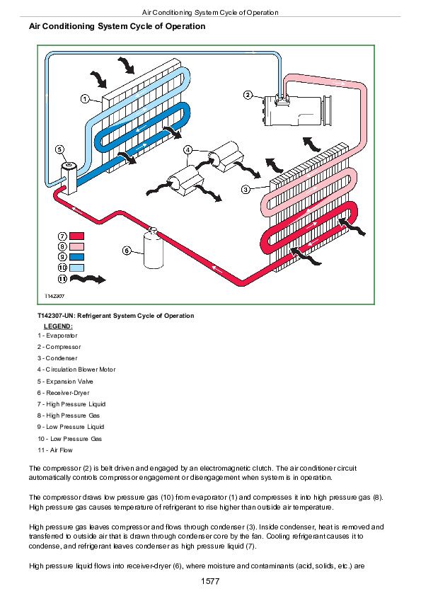
Air Conditioning System Cycle of Operation
Group 15: Diagnostic Information
Air Conditioning System Does Not Operate
Air Conditioner Does Not Cool Interior of Cab
Heater System Does Not Operate
Heater Does Not Warm Interior of Cab
Interior Windows Continue to Fog Using Heater
Heater and Air Conditioner Component Location
Group 25: Tests
Refrigerant Cautions and Proper Handling
Heater and Air Conditioner Operational Checks
Air Conditioner Compressor Clutch Test
Refrigerant Leak Test
Refrigerant Hoses and Tubing Inspection
R134a Air Conditioning System Test
Operating Pressure Diagnostic Chart
Section 9900: Dealer Fabricated Tools
Group 99: Dealer Fabricated Tools
DFT1364 Split Flange Hose Cap
John Deere E330LC Excavator Operation and Test Service Manual (TM13103X19)


