John Deere Tractors 5076EF Repair Service Manual (TM607619)
Catalog:
Model:
Complete service repair manual for John Deere 5076EF Tractor (January 2013), with all the shop information to maintain, diagnostic, repair, refurbish/rebuild like professional mechanics.
John Deere Tractors 5076EF workshop service & repair manual includes:
* Numbered table of contents easy to use so that you can find the information you need fast.
* Detailed sub-steps expand on repair procedure information
* Numbered instructions guide you through every repair procedure step by step.
* Troubleshooting and electrical service procedures are combined with detailed wiring diagrams for ease of use.
* Notes, cautions and warnings throughout each chapter pinpoint critical information.
* Bold figure number help you quickly match illustrations with instructions.
* Detailed illustrations, drawings and photos guide you through every procedure.
* Enlarged inset helps you identify and examine parts in detail.
TM607619 English - John Deere Tractors 5076EF Technical Manual (January 2013) (Repair).PDF
tm607628 French - 5076EF TractorRepair Technical Manual (January 2013)
tm607654 Portuguese - 5076EF TractorRepair Technical Manual(January 2013)
tm607659 Russian - Трактор 5076EFТехническое руководство по ремонту(январь 2013 г.)
Total Pages: 833 pages
File Format: PDF (bookmarked, ToC, Searchable, Printable)
Language: English French Portuguese Russian
MAIN SECTIONS
Foreword
General Information
Safety
General Specifications
Fuel and Lubricants
Serial Number Locations
Features and Accessories
Engine Repair
Engine
Cooling System
Fuel System
Fuel System
Air Intake System
Speed Control Linkage
Electrical Repair
Battery, starter and alternator
Electrical system components
Wiring Harness
Power Train Repair
Clutch Housing
Clutch Assembly - Synchronized Transmissions
Synchronized Transmission
Rear PTO Drive Shaft
Differential
Final Drive
Mechanical Front Wheel Drive
Creeper Assembly
Steering and Brake Repair
Steering Repair
Brake Repair
Hydraulic Repair
Hydraulic pump and filter
Hydraulic Oil Cooler
Rockshaft
Dual Selective Control Valve
Single Selective Control Valve
Hydraulic Power Beyond
Miscellaneous Repair
Front Axle-2WD
Wheels
3-Point Hitch
Fenders
Hood
Operator Station Repair
Seat and Support
Control Console and Panel
ROLL-GARD®
Rear Bar
Dealer Fabricated Tools
Dealer Fabricated Tools
TABLE OF CONTENTS
Section 10: General Information................17
Group 05: Safety................17
Recognize Safety Information................22
Understand Signal Words................23
Follow Safety Instructions................24
Prepare for Emergencies................25
Wear Protective Clothing................26
Protect Against Noise................27
Handle Fuel Safely—Avoid Fires................28
Handle Starting Fluid Safely................29
Keep ROPS Installed Properly................30
Use Foldable ROPS and Seat Belt Properly................31
Stay Clear of Rotating Drivelines................32
Use Steps and Handholds Correctly................34
Read Operator Manuals for ISOBUS Implements................35
Use Seat Belt Properly................36
Operating the Tractor Safely................37
Limited Use in Forestry Operation................39
Operating the Loader Tractor Safely................40
Keep Riders Off Machine................41
Instructional Seat................42
Use Safety Lights and Devices................43
Use a Safety Chain................44
Transport Towed Equipment at Safe Speeds................45
Use Caution On Slopes and Uneven Terrain................47
Freeing a Mired Machine................48
Avoid Contact with Agricultural Chemicals................49
Handle Agricultural Chemicals Safely................50
Handling Batteries Safely................52
Avoid Heating Near Pressurized Fluid Lines................54
Remove Paint Before Welding or Heating................55
Handle Electronic Components and Brackets Safely................56
Practice Safe Maintenance................57
Exhaust Filter Cleaning................58
Work In Ventilated Area................59
Support Machine Properly................60
Prevent Machine Runaway................61
Park Machine Safely................62
Transport Tractor Safely................63
Service Cooling System Safely................64
Service Accumulator Systems Safely................65
Service Tires Safely................66
Service Front-Wheel Drive Tractor Safely................67
Tightening Wheel Retaining Bolts/Nuts................68
Avoid High-Pressure Fluids................69
Do Not Open High-Pressure Fuel System................70
Store Attachments Safely................71
Dispose of Waste Properly................72
Group 10: General Specifications................652
Machine Specifications................652
Machine Specifications, continued................79
Machine Specifications, continued................79
Machine Specifications , continued................80
Machine Dimensions................81
Ground Speed Estimates................83
Repair Specifications................652
Repair Specifications - Cont..................92
Repair Specifications - Cont..................92
Repair Specifications - Cont..................92
Repair Specifications - Cont..................92
Repair Specifications - Cont..................92
Repair Specifications - Cont..................92
Repair Specifications - Cont..................92
Repair Specifications - Cont..................92
Service Recommendations for O-Ring Boss Fittings................93
Service Recommendations for Flat Face O-Ring Seal Fittings................95
Metric Cap Screw Torque Values—Grade 7................97
Metric Bolt and Cap Screw Torque Values................98
Unified Inch Bolt and Cap Screw Torque Values................99
Abbreviations................100
Group 20: Fuel and Lubricants................19
Diesel Fuel Specifications................652
Lubricity of Diesel Fuel................103
Diesel Fuel Storage................104
Do Not Use Galvanized Containers................105
Fill Fuel Tank................106
Diesel Engine Oil................107
Heavy Duty Diesel Engine Coolant................108
Engine Break - In Oil................109
Engine Cooling System................110
Liquid Coolant Conditioner................112
Transmission and Hydraulic Oil................113
MFWD Gear Oil................114
Grease (Specific Application)................115
Grease................116
Alternative and Synthetic Lubricants................118
Lubricant Storage................119
Group 25: Serial Number Locations................19
Serial Numbers................121
Product Identification Number Location................122
Engine Serial Number Location................123
Fuel injection pump serial number location................124
Alternator Identification Number Location................125
Power Steering Valve Serial Number Location................126
Transmission Serial Number Location................127
Front Axle (2WD) Serial Number Location................128
Mechanical Front Wheel Drive (MFWD) Serial Number Location................129
Group 30: Features and Accessories................131
Features and Accessories................131
Standard Features................135
Standard Features................135
Standard Features................135
Operating Foldable ROPS — If Equipped................136
Factory Installed Optional Equipment................138
Field Installed Optional Kits and Accessories................139
Section 20: Engine Repair................140
Group 05: Engine................140
Service Equipment and Tools................651
Specifications................652
John Deere Engine Repair—Use CTM................144
Remove Engine................145
Install Engine................155
Group 10: Cooling System................140
Specifications................652
Engine Coolant Pump Repair—Use CTM................168
Remove right-side fan guard................169
Remove left-side fan guard................170
Remove and Install Coolant Recovery Tank................171
Remove and Inspect Radiator................175
Install Radiator................179
Remove and Install Thermostat................182
Inspect and Replace Belt Tensioner................185
Section 30: Fuel System................188
Group 05: Fuel System................188
Injection Pump, Nozzle and Governor Repair—Use CTM................190
Remove, Inspect and Install Fuel Tank—Reference Listing................191
Remove, Inspect, and Install Fuel Tank................192
Replace Fuel Filter (Engine Tier 0)................196
Replace Fuel Filter/Water Separator (Engine Tier 2)................197
Remove and Install Fuel Filter/Primer Pump Assembly (Engine Tier 0)................198
Remove and Install Fuel Filter/Primer Pump Assembly (Engine Tier 2)................199
Remove and Install The Water Separator Assembly................200
Group 10: Air Intake System................188
Turbocharger Repair—Use CTM................202
Specifications................652
Other Material................717
Remove, Inspect, and Install Air Cleaner Elements................205
Remove Turbocharger................208
Install Turbocharger................210
Turbocharger Break-In................212
Group 15: Speed Control Linkage................188
Inspect and Repair Speed Control Linkage—Reference Listing................214
Inspect and Repair Speed Control Linkage................215
Section 40: Electrical Repair................217
Group 05: Battery, starter and alternator................217
Starter Repair—Use CTM................220
Prevent Battery Explosions................221
Remove and Install Battery................222
Remove and Install Starter................223
Replace Alternator/Regulator................224
Group 10: Electrical system components................217
Essential Tools................494
Other Material................717
Specifications................652
Replace Air Filter Restriction Switch................230
Replace Cold Start Advance Switch................231
Replace Coolant Temperature Sender................233
Replace Engine Speed Sensor................234
Replace Engine Oil Pressure Switch................235
Replace Key Switch—Reference Listing................236
Replace Key Switch................237
Replace Light Switch................239
Replace Turn Signal Switch—Reference Listing................241
Replace Turn Signal Switch................242
Replace Instrument Panel—Reference Listing................244
Replace Instrument Panel................245
Replace Rear PTO Switch—Reference Listing................249
Replace Rear Mechanical PTO Switch................250
Replace Neutral Start Switch................251
Replace Fuel Level Sender................252
Replace Seat Switch—Reference Listing................253
Replace Seat Switch................254
Replace Clutch Pedal Position Sensor— Synchronized Transmission................259
Replace Clutch Disengage Switch— Synchronized Transmission................262
Replace Park Switch— Synchronized Transmission (If Equipped)................265
Replace Brake Pedal Switch—Electro-Hydraulic Tractors (If Equipped)................266
Replace VEC Load Center................267
Group 15: Wiring Harness................218
Service Equipment and Tools................651
Essential Tools................494
Service Parts Kits................718
Replace Connector Body—Blade Terminals................272
Replace WEATHER PACK WEATHER PACK is a trademark of Packard Electric. Connector................218
Install WEATHER PACK WEATHER PACK is a trademark of Packard Electric. Contact................218
Repair (Pull Type) Metri-Pack® Connectors................277
Repair (Push Type) Metri-Pack® Connectors................279
Replace Front Wiring Harness................282
Replace Rear Wiring Harness................284
Section 50: Power Train Repair................286
Group 05: Clutch Housing................286
Service Equipment and Tools................651
Other Material................717
Specifications................652
Separate Engine from Clutch Housing—Reference Listing................295
Separate Engine from Clutch Housing................296
Install Engine to Clutch Housing—Reference Listing................303
Install Engine to Clutch Housing................304
Inspect and Repair Clutch Pedal and Linkage—Reference Listing................310
Inspect and Repair Clutch Pedal and Linkage................311
Group 10: Clutch Assembly — Synchronized Transmissions................286
Essential Tools................494
Service Equipment and Tools................651
Other Material................717
Specifications................652
Remove and Install Clutch Assembly................318
Disassemble and Inspect Clutch Assembly................322
Assemble Clutch Assembly................331
Traction Clutch Finger Adjustment................337
PTO Clutch Finger Adjustment................339
Remove and Inspect Clutch Release Mechanism and Shafts................341
Install Clutch Release Mechanism and Shafts................345
Group 15: Synchronized Transmission................286
John Deere Transmission Repair................349
Essential Tools................494
Service Equipment and Tools................651
Other Material................717
Specifications................652
Separate Clutch Housing from Transmission—Reference Listing................354
Separate Clutch Housing from Transmission................355
Install Clutch Housing to Transmission—Reference Listing................361
Install Clutch Housing to Transmission................362
Inspect and Repair Gear and Range Shift Levers - Reference Listing................368
Inspect and Repair Gear Shift Lever................369
Inspect and Repair Range Shift Lever................372
Remove Transmission—Reference Listing................375
Remove Transmission - Synchronized Transmissions (NM, NP, NM05, NP05)................376
Disassemble and Inspect Transmission—Reference Listing................382
Disassemble and Inspect Transmission (NM, NP, NM05, NP05)................383
Assemble Transmission—Reference Listing................387
Assemble and Install Transmission (NM, NP, NM05, NP05)................388
Install Transmission—Reference Listing................397
Disassemble, Inspect and Assemble Gear Shift Shaft Assemblies—Reference Listing................398
Disassemble, Inspect and Assemble Gear Shift Shaft Assemblies (NM, NP, NM05, NP05)................399
Disassemble, Inspect, and Assemble Transmission Top Shaft—Reference Listing................401
Disassemble, Inspect, and Assemble Transmission Top Shaft (NM, NP, NM05, NP05)................402
Disassemble, Inspect, and Assemble Range Reduction Shaft—Reference Listing................405
Disassemble, Inspect, and Assemble Range Reduction Shaft (NM, NP, NM05, NP05)................406
Disassemble, Inspect and Assemble Driven Shaft—Reference Listing................408
Disassemble, Inspect, and Assemble Driven Shaft (NM, NP, NM05, NP05)................409
Remove, Inspect, and Install MFWD and Range Gears—Reference Listing................411
Remove, Inspect, and Install MFWD and Range Gears (NM, NP, NM05, NP05)................412
Remove, Inspect, and Install Reverse Idler Shaft—Reference Listing................414
Inspect and Repair Park Brake Lever (if equipped)................415
Remove, Inspect, and Repair Park Brake (if equipped)................417
Group 20: Rear PTO Drive Shaft................287
Service Equipment and Tools—Reference Listing................444
Service Equipment and Tools................651
Other Material—Reference Listing................446
Other Material................717
Specifications—Reference Listing................448
Specifications................652
Inspect and Repair Rear PTO Lever and Linkage—Reference Listing................426
Inspect and Repair PTO Lever and Linkage................427
Inspect and Repair PTO 540/540E Shift Lever and Linkage................429
Remove and Install Rear PTO Drive Shaft Assembly—Reference Listing................431
Remove and Install Standard and 540/540E Rear PTO Drive Shaft Assembly................432
Disassemble, Inspect and Assemble Rear PTO Drive Shaft Assembly—Reference Listing................434
Disassemble, Inspect and Assemble Standard Rear PTO Drive Shaft Assembly................435
Disassemble, Inspect, and Assemble Rear 540/540E PTO Drive Shaft Assembly................438
Group 25: Differential................288
Essential Tools—Reference Listing................442
Essential Tools................494
Service Equipment and Tools—Reference Listing................444
Service Equipment and Tools................651
Other Material—Reference Listing................446
Other Material................717
Specifications—Reference Listing................448
Specifications................652
Service Parts Kits—Reference Listing................450
Service Parts Kits................718
Remove and Install Differential Assembly—Reference Listing................452
Remove and Install Differential Assembly................453
Disassemble, Inspect, and Assemble Differential Assembly—Reference Listing................455
Disassemble, Inspect, and Assemble Differential Assembly................456
Remove and Inspect Differential Drive Shaft—Reference Listing................458
Remove and Inspect Differential Drive Shaft................459
Install Differential Drive Shaft—Reference Listing................463
Install Differential Drive Shaft................464
Remove, Inspect, and Install Differential Lock Assembly—Reference Listing................468
Remove, Inspect, and Install Differential Lock Assembly................469
Differential Cone Point Adjustment—Reference Listing................471
Differential Cone Point Adjustment................472
Differential Backlash Adjustment—Reference Listing................474
Differential Backlash Adjustment................475
Group 30: Final Drive................288
Service Equipment and Tools................651
Other Material................717
Remove and Install Final Drive Assembly—Reference Listing................480
Remove and Install Final Drive Assembly................481
Remove and Inspect Planetary Drive Assembly................483
Install Planetary Drive Assembly................486
Remove, Inspect, and Install Axle Shaft Assembly................489
Group 35: Mechanical Front Wheel Drive................289
Special or Essential Tools................494
Tools................494
Other Material................717
Inspect and Repair MFWD Lever and Linkage—Reference Listing................496
Inspect and Repair MFWD Lever and Linkage................497
Remove and Install MFWD Drop Gearbox................499
Disassemble and Inspect MFWD Drop Gearbox................500
MFWD Drop Gearbox Cross Section................503
Assemble MFWD Drop Gearbox................505
Remove, Inspect and Install MFWD Drive Shaft—Reference Listing................510
Remove, Inspect, and Install MFWD Drive Shaft................511
Remove and Install MFWD Axle Housing Assembly—Reference Listing................513
Remove and Install MFWD Axle Housing Assembly................514
Remove and Install MFWD Axle Pivot Pin and Pivot Bushings................517
Remove, Inspect and Install MFWD Axle Supports—Reference Listing................519
Remove, Inspect and Install MFWD Axle Supports................520
Disassemble and Inspect MFWD Outer Drive—Reference Listing................531
Disassemble and Inspect MFWD Outer Drive................532
Assemble MFWD Outer Drive—Reference Listing................536
Assemble MFWD Outer Drive................537
Remove, Inspect and Install MFWD Knuckle Housing—Reference Listing................540
Repair the Knuckle Housing and the King Pin................541
Remove, Inspect, and Install MFWD Axle Shaft—Reference Listing................543
Remove, Inspect, and Install MFWD Axle Shaft................544
Remove and Install MFWD Differential Carrier Assembly................546
Disassemble and Inspect MFWD Differential Carrier Assembly................548
Assemble MFWD Differential Carrier Assembly................553
Filling/Draining Planetary Drive................570
Filling/Draining MFWD Axle Housing................572
Group 40: Creeper Assembly................290
Other Material................717
Remove and Install Creeper Assembly................579
Remove and Install Creeper Assembly................579
Disassemble, Inspect, and Assemble Creeper Assembly................582
Section 60: Steering and Brake Repair................584
Group 05: Steering Repair................584
Other Material................717
Specifications................652
Service Parts Kits................718
Remove and Install Steering Column and Valve—Reference Listing................590
Remove and Install Straight Steering Column and Valve (without oil cooler)................591
Remove and Install Tilt Steering Column (if equipped)................593
Remove and Install Steering Valve (with oil cooler)................595
Disassemble and Inspect Steering Valve................597
Assemble Steering Valve................601
Remove and Install Steering Cylinder—Reference Listing................606
Remove and Install Steering Cylinder—2WD Axle................607
Disassemble, Inspect, and Assemble Steering Cylinder—Reference Listing................609
Disassemble, Inspect, and Assemble Steering Cylinder—2WD Axle................610
Remove and Install Steering Cylinder—MFWD Axle—Reference Listing................612
Remove and Install Steering Cylinder—MFWD Axle................613
Disassemble, Inspect, and Assemble Steering Cylinder—MFWD Axle—Reference Listing................615
Disassemble, Inspect, and Assemble Steering Cylinder— MFWD Axle................616
Remove, Inspect and Install Tie Rod Assembly—2WD Axle—Reference Listing................618
Remove, Inspect and Install Tie Rod Assembly—2WD Axle................619
Remove, Inspect and Install Tie Rod Assembly—MFWD Axle—Reference Listing................621
Remove, Inspect and Install Tie Rod Assembly—MFWD Axle................622
Inspect and Replace Steering Hydraulic Lines—Reference Listing................624
Inspect and Replace Steering Hydraulic Lines—without oil cooler................625
Group 10: Brake Repair................584
Other Material................717
Remove and Install Brake Valve and Pedals................629
Disassemble and Inspect Brake Valve................631
Brake Valve Cross Section................634
Assemble Brake Valve................636
Remove and Inspect Brakes................639
Install Brakes................642
Inspect and Replace Brake Hydraulic Lines................645
Section 70: Hydraulic Repair................647
Group 05: Hydraulic pump and filter................647
Service Parts Kit................650
Service Equipment and Tools................651
Specifications................652
Remove, Inspect, and Install Hydraulic Oil Pick-Up Screen................653
Remove and Install Hydraulic Pump................654
Remove Hydraulic Pump External Components................655
Disassemble and Inspect Hydraulic Pump................657
Assemble Hydraulic Pump................660
Install Hydraulic Pump External Components................662
Remove and Install Hydraulic Oil Filter/Manifold................664
Inspect and Replace Hydraulic Supply/Return Lines................665
Group 06: Hydraulic Oil Cooler................647
Remove, Inspect, and Install Hydraulic Oil Cooler-Reference Listing................668
Remove, Inspect, and Install Hydraulic Oil Cooler................669
Group 10: Rockshaft................647
Other Material................717
Service Parts Kits................718
Inspect and Repair Rockshaft Control Lever Assembly—Reference Listing................674
Inspect and Repair Rockshaft Control Lever Assembly................675
Inspect and Repair Rockshaft Control Linkage................685
Inspect and Repair Rockshaft Control Linkage................685
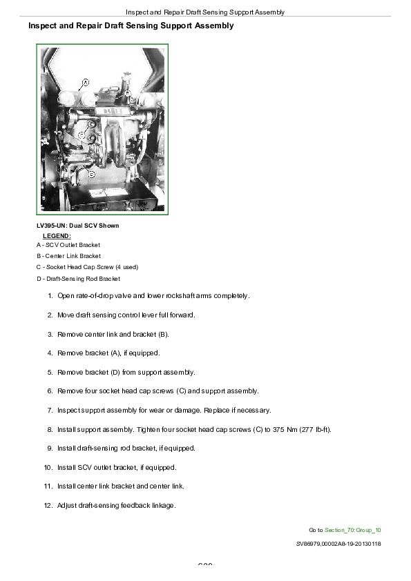
Inspect and Repair Draft Sensing Support Assembly................689
Replace Main Relief Valve................690
Replace Rockshaft Surge Relief Valve................692
Remove, Inspect, and Install Rate-of-Drop Valve................693
Replace Rockshaft Control Valve................695
Remove and Install Rockshaft Case................698
Remove, Inspect, and Install Rockshaft Lift Arms................700
Remove, Inspect, and Install Rockshaft Piston and Cylinder................702
Group 15: Dual Selective Control Valve................647
Other Material................717
Service Parts Kits................718
Remove and Install Dual Selective Control Valve (SCV)................707
Disassemble, Inspect, and Assemble Dual Selective Control Valve (SCV)................710
Inspect and Replace Hydraulic Hoses—Dual Selective Control Valve (SCV)................714
Group 16: Single Selective Control Valve................648
Other Material................717
Service Parts Kits................718
Inspect and Repair SCV Levers and Linkage................719
Remove and Install Single Selective Control Valve (SCV)—Reference Listing................720
Remove and Install Selective Control Valve (SCV)................721
Disassemble, Inspect and Assemble Single (Third) Selective Control Valve (SCV)—Reference Listing................723
Disassemble, Inspect, and Assemble Selective Control Valve (SCV)................724
Group 20: Hydraulic Power Beyond................648
Remove and Install Hydraulic Lines and Fittings—Power Beyond Hook-Up—Reference Listing................730
Install and Remove Hydraulic Lines and Fittings—Power Beyond Hook-Up................731
Section 80: Miscellaneous Repair................735
Group 05: Front Axle—2WD................735
Remove and Install Front Axle—2WD—Reference Listing................737
Remove and Install Front Axle—2WD................738
Inspect and Replace Pivot Pin and Bushings—2WD Axle................741
Remove and Install Spindle Assembly—2WD Axle—Reference Listing................743
Remove and Install Spindle Assembly—2WD Axle................744
Inspect and Replace Spindle Shaft Bushings—2WD Axle................746
Group 10: Wheels................735
Inspect and Replace Front Wheel Bearings—Reference Listing................748
Inspect and Replace Front Wheel Bearings—2WD................749
Group 15: 3-Point Hitch................735
Inspect and Repair Draft Links—Reference Listing................752
Inspect and Repair Draft Link................753
Inspect and Repair Lift Link—Reference Listing................754
Inspect and Repair Adjustable Lift Links................755
Inspect and Repair Center Link—Reference Listing................757
Inspect and Repair Center Link................758
Remove and Install Drawbar and Support—Reference Listing................760
Remove and Install Drawbar and Support................761
Group 20: Fenders................735
Remove and Install Fenders—Reference Listing................764
Remove and Install Fenders................765
Group 25: Hood................735
Remove and Install Hood................770
Section 90: Operator Station Repair................772
Group 05: Seat and Support................772
Remove and Install Seat and Support—Reference Listing................774
Remove and Install Seat and Support................775
Group 06: Control Console and Panel................772
Remove and Install Right-Side Control Console and Panel................779
Remove and Install Cowl Cover................782
Group 10: ROLL-GARD®................772
Remove and Install Roll-Gard™—Reference Listing................786
Remove and Install Roll-Gard™................787
Group 12: Rear Bar................772
Remove and Install Rear Bar................793
Section 99: Dealer Fabricated Tools................798
Group 00: Dealer Fabricated Tools................494
PTO Clutch Finger Height Gauge................800
Traction Clutch Finger Height Gauge................801
Traction Clutch Finger Height Adjustment Tool................802
DFLV1A Final Drive Turning Tool................803
DFRW20—Compressor Holding Fixture................804
John Deere Tractors 5076EF Repair Service Manual (TM607619)


