John Deere Tractors 5055E, 5060E, 5065E, 5075E Repair Service Manual (TM901919)
Catalog:
Model:
Complete Repair Service Technical Manual for John Deere Tractors 5055E, 5060E, 5065E & 5075E (Asia, India), with workshop information to maintain, repair, and service like professional mechanics.
John Deere Tractors 5055E, 5060E, 5065E & 5075E workshop technical manual (repair) includes:
* Numbered table of contents easy to use so that you can find the information you need fast.
* Detailed sub-steps expand on repair procedure information
* Numbered instructions guide you through every repair procedure step by step.
* Notes, cautions and warnings throughout each chapter pinpoint critical information.
* Bold figure number help you quickly match illustrations with instructions.
* Detailed illustrations, drawings and photos guide you through every procedure.
* Enlarged inset helps you identify and examine parts in detail.
tm901919 - 5310, 5055E, 5060E, 5065E And 5075E Tractors Repair Technical Manual (India and Asia Edition) Technical Manual.pdf
PRODUCT DETAILS:
Total Pages: 827 pages
File Format: PDF (PC/Mac/Android/Kindle/iPhone/iPad; bookmarked, ToC, Searchable, Printable)
Language: English
MAIN SECTIONS
Foreword
General Information
Safety
General Specifications
Fuel and Lubricants
Serial Number Locations
Features and Accessories
Engine Repair
Engine
Cooling System
Fuel, Air Intake and Exhaust Systems
Fuel System
Air Intake and Exhaust System
Speed Control Linkage
Electrical Repair
Battery, Starter and Alternator
Electrical System Components
Wiring Harness
Power Train Repair (12x12 PR Transmission)
Clutch Housing
Clutch Assembly
Transmission
Rear PTO
Differential
Final Drives
Mechanical Front Wheel Drive
Power Train Repair (9x3 TSS Transmission)
Clutch Housing
Clutch Assembly
Transmission
Rear PTO
Differential
Final Drives
Mechanical Front Wheel Drive
Steering and Brake Repair
Steering Repair
Brake Repair
Trailer Brake Valve Repair
Hydraulic Repair
Hydraulic Pump and Filter
JD Rockshaft
Selective Control Valve (SCV)
Miscellaneous Repair
Front Axle
Wheels
3-Point Hitch
Hood
Ballast
Operator Station Repair (OOS)
Seat and Support
Control Console and Panel
Roll-GardROLL-GARD is a trademark of Deere & Company.
Operator Platform
Fenders
Canopy (If Equipped)
Operator Station Repair (Cab)
Seat and Support
Control Console and Panel
Cab Components
Air Conditioning System
Heating System
TABLE OF CONTENTS
Section 10: General Information................16
Group 05: Safety................16
Recognize Safety Information................20
Understand Signal Words................21
Follow Safety Instructions................22
Handle Fluids Safely—Avoid Fires................23
Prevent Battery Explosions................24
Prepare for Emergencies................25
Prevent Acid Burns................26
Service Cooling System Safely................28
Avoid High-Pressure Fluids................29
Park Machine Safely................30
Support Machine Properly................31
Wear Protective Clothing................32
Work in Clean Area................33
Service Machines Safely................34
Work In Ventilated Area................35
Illuminate Work Area Safely................36
Replace Safety Signs................37
Use Proper Lifting Equipment................38
Service Tires Safely................39
Avoid Harmful Asbestos Dust................40
Avoid Heating Near Pressurized Fluid Lines................41
Remove Paint Before Welding or Heating................42
Use Proper Tools................43
Dispose of Waste Properly................44
Live With Safety................45
Group 10: General Specifications (9x3 TSS Transmission)................16
Machine Specifications................758
Repair Specifications................758
Ground Speed Estimates — Sync Shuttle Transmission................53
Service Recommendations for O-Ring Boss Fittings................75
Service Recommendations for Flat Face O-Ring Seal Fittings................77
Metric Bolt and Cap Screw Torque Values................79
Unified Inch Bolt and Cap Screw Torque Values................80
Glossary of Terms................82
Group 11: General Specifications (12x12 PR Transmission)................17
Machine Specifications................758
Repair Specifications................758
Ground Speed Estimates — PowrReverser PowrReverser is a trademark of Deere & Company Transmission................17
Service Recommendations for O-Ring Boss Fittings................75
Service Recommendations for Flat Face O-Ring Seal Fittings................77
Metric Bolt and Cap Screw Torque Values................79
Unified Inch Bolt and Cap Screw Torque Values................80
Glossary of Terms................82
Group 15: Fuel and Lubricants................17
Diesel Fuel................88
Handling and Storing Diesel Fuel................90
Lubricity of Diesel Fuel................91
Testing Diesel Fuel................92
BioDiesel Fuel................93
Do Not Use Galvanized Containers................95
Fill Fuel Tank................96
Diesel Engine Break-In Oil — Non-Emissions Certified and Certified Tier 1, Tier 2, Tier 3, Stage I, Stage II, and Stage III................98
Diesel Engine Oil — Interim Tier 4, Final Tier 4, Stage IIIB, and Stage IV................100
Oil Filters................102
Diesel Engine Coolant (engine with wet sleeve cylinder liners)................103
Operating in Warm Temperature Climates................105
Testing Diesel Engine Coolant................106
Transmission and Hydraulic Oil................107
Additional Information About Diesel Engine Coolants and John Deere LIQUID COOLANT CONDITIONER................109
Use Correct Transmission/Hydraulic Filter Element................111
MFWD Axle Housing and Wheel Hub Oil................112
Grease................113
Mixing of Lubricants................114
Alternative and Synthetic Lubricants................115
Lubricant Storage................116
Group 20: Serial Number Locations................18
Serial Numbers................118
Product Identification Number................119
Record Engine Serial Number................120
Fuel Injection Pump Serial Number................121
Alternator Serial Number Location................122
Power Steering Valve Serial Number Location................123
Starter Serial Number Location................124
Transaxle Serial Number Location (12x12 PR Transmission)................125
Record Mechanical Front Wheel Drive (MFWD) Serial Number................126
Group 25: Features and Accessories................128
Features and Accessories................128
Standard Features................129
Factory Installed Optional Equipment................131
Field Installed Optional Kits and Accessories................132
Section 20: Engine Repair................133
Group 05: Engine................133
Service Equipment and Tools................756
Specifications................758
John Deere Engine Repair—Use CTM................137
Remove Engine — Cab................138
Remove Engine — OOS................147
Install Engine — Cab................153
Install Engine — OOS................160
Group 30: Cooling System................133
Special or Essential Tools................753
Specifications................758
Torques for Hardware................170
Clean Front Grille, Radiator, Condenser (Sync Shuttle)................171
Clean Front Grille, Radiator, Condenser, Oil Cooler and Fuel Cooler (PowrReverser PowrReverser is a trademark of Deere & Company )................133
Remove and Inspect Radiator (OOS)................176
Remove and Inspect Radiator (Cab)................181
Water Pump — Exploded View................185
Install Radiator................186
Replace Thermostat................190
Section 30: Fuel, Air Intake and Exhaust Systems................193
Group 05: Fuel System................193
Special or Essential Tools................753
Injection Pump, Nozzle and Governor Repair—Use CTM................202
Remove, Inspect and Install Fuel Tank (OOS)................203
Remove, Inspect and Install Fuel Tank (Cab)................205
Group 10: Air Intake and Exhaust System................193
Remove, Inspect, and Install Air Cleaner Elements................211
Check Air Inlet Pipe with Turbocharger................213
Exhaust Manifold Inspection................214
Remove Turbocharger................215
Install Turbocharger................216
Group 15: Speed Control Linkage................193
Inspect and Repair Speed Control Linkage (OOS)................221
Inspect and Repair Speed Control Linkage (Cab)................223
Section 40: Electrical Repair................225
Group 05: Battery, Starter and Alternator................225
Starter Repair—Use CTM................228
Remove and Install Battery (OOS)................229
Remove and Install Battery (Cab)................231
Remove and Install Starter................233
Replace Alternator/Regulator................234
Group 10: Electrical System Components................225
Service Equipment and Tools................756
Other Material................757
Replace Air Filter Restriction Sensor................239
Replace Coolant Temperature Sender................240
Replace Engine Speed Sensor................241
Replace Engine Oil Pressure Sensor................242
Replace Key Switch (OOS)................243
Replace Key Switch (CAB)................244
Replace Light Switch................247
Replace Turn Signal Controller................249
Replace Instrument Panel (OOS)................250
Replace Instrument Panel (CAB)................251
Replace Rear PTO ON/OFF Switch (PR Transmission™)................253
Replace Clutch Pedal Position Sensor (PR Transmission™)................254
Remove and Install Rear PTO Switch (TSS Transmission)................257
Replace Park Position Start Switch................265
Replace Seat Switch (OOS)................266
Replace Fuel Level Sender (OOS)................268
Replace Fuel Level Sender (CAB)................269
Group 15: Wiring Harness................225
Special or Essential Tools................753
Service Parts Kits................527
Remove Connector Body from Blade Terminals................274
Replace WEATHER PACK WEATHER PACK is a trademark of Packard Electric. Connector................225
Install WEATHER PACK WEATHER PACK is a trademark of Packard Electric. Contact................226
Replace Battery Positive Cable (OOS)................279
Replace Battery Positive Cable (Cab)................280
Replace Battery Positive Cable................281
Replace Hood Wiring Harness................282
Replace Beacon Lamp Wiring Harness................284
Replace Engine Wiring Harness (OOS)................285
Replace Engine Wiring Harness (Cab)................287
Replace Console Wiring Harness (9x3 TSS Transmission)................289
Replace Console Wiring Harness—Cab (12x12 PR Transmission™)................291
Replace Rear Wiring Harness (9x3 TSS Transmission)................293
Replace Rear Wiring Harness (12x12 PR Transmission™)................295
Replace 7 Pin Connector Wiring Harness................298
Section 50: Power Train Repair (12x12 PR Transmission)................299
Group 05: Clutch Housing................299
John Deere Transmission Repair — Use CTM................418
Specifications................758
Separate Engine from Clutch Housing (PR)................304
Install Engine to Clutch Housing (PR)................312
Remove, Inspect, and Repair Clutch Pedal and Linkage (PR)................320
Group 10: Clutch Assembly................299
Specifications................758
John Deere Transmission Repair — Use CTM................418
Adjust Clutch Pedal and Linkage................325
Group 15: Transmission................299
Other Material................757
Specifications................758
John Deere Transmission Repair — Use CTM................418
Inspect and Repair Gear Shift Lever................405
Inspect and Repair Range Shift Lever................407
Inspect and Repair Range Inspect and Repair Range Inspect and Repair Range & Gear Shift Lever{pgNO}299 Gear Shift Lever{pgNO}409 Gear Shift Lever................335
Group 21: Rear PTO................299
Other Material................757
Specifications................758
John Deere Transmission Repair — Use CTM................418
Group 26: Differential................299
Essential Tools................753
Service Equipment and Tools................756
Other Material................757
Specifications................758
Service Parts Kits................527
John Deere Transmission Repair — Use CTM................418
Group 30: Final Drives................299
Service Equipment and Tools................756
Other Material................757
Specifications................758
John Deere Transmission Repair — Use CTM................418
Group 35: Mechanical Front Wheel Drive................300
Mechanical Front Wheel Drive – If Equipped—Summary of References................436
Service Equipment and Tools................756
Essential Tools................753
Other Material................757
Specifications................758
MFWD Axle Repair — Use CTM................362
MFWD Dropbox Repair—Use CTM................363
Remove, Inspect and Install MFWD Drive Shaft(PR)................364
Remove and Install MFWD Axle Housing Assembly(PR)................365
Remove, Inspect and Install MFWD Axle Supports (Without Paddy Seal)(PR)................367
Section 51: Power Train Repair (9x3 TSS Transmission)................369
Group 05: Clutch Housing................369
John Deere Transmission Repair — Use CTM................418
Service Equipment and Tools................756
Other Material................757
Essential Tools................753
Specification................611
Separate Engine from Clutch Housing (TSS)................377
Install Engine to Clutch Housing (TSS)................385
Inspect and Repair Clutch Pedal and Linkage (TSS)................393
Group 10: Clutch Assembly................369
Specification................611
Traction Clutch Finger Adjustment................397
PTO Clutch Finger Adjustment................399
John Deere Transmission Repair — Use CTM................418
Group 15: Transmission................369
Specifications................758
John Deere Transmission Repair — Use CTM................418
Inspect and Repair Gear Shift Lever................405
Inspect and Repair Range Shift Lever................407
Inspect and Repair Range Inspect and Repair Range Inspect and Repair Range & Gear Shift Lever{pgNO}369 Gear Shift Lever{pgNO}409 Gear Shift Lever................335
Group 21: Rear PTO................369
Other Material................757
Specifications................758
John Deere Transmission Repair — Use CTM................418
Remove, Inspect and Install Rear PTO Lever and Linkage................415
Group 26: Differential................369
John Deere Transmission Repair — Use CTM................418
Group 30: Final Drives................369
Service Equipment and Tools................756
Other Material................757
Specifications................758
Remove and Install Final Drive Assembly................423
Remove and Inspect Planetary Drive Assembly................425
Install Planetary Drive Assembly................428
Remove, Inspect, and Install Axle Shaft Assembly................431
Group 35: Mechanical Front Wheel Drive................370
Mechanical Front Wheel Drive – If Equipped—Summary of References................436
Service Equipment and Tools................756
Essential Tools................753
Other Material................757
Specifications................758
MFWD Axle Repair—Use CTM................444
Inspect and Repair MFWD Lever and Linkage................445
Remove and Install MFWD Drop Gearbox................446
Disassemble and Inspect MFWD Drop Gear box................448
MFWD Drop Gearbox Cross Section................451
Assemble MFWD Drop Gearbox................453
Remove, Inspect and Install MFWD Drive Shaft................459
Remove and Install MFWD Axle Housing Assembly................460
Remove, Inspect and Install MFWD Axle Supports (Without Paddy Seal)................462
Section 60: Steering and Brake Repair................464
Group 05: Steering Repair................464
Other Material................757
Specifications................758
Service Parts Kits................527
Remove and Install Steering Column and Valve................469
Disassemble and Inspect Steering Valve - Sauer Danfoss................471
Assemble Steering Valve - Sauer Danfoss................475
Disassemble and Inspect Steering Valve - Eaton................480
Assemble Steering Valve - Eaton................485
Remove and Install Steering Cylinder (Global Front Axle)................491
Disassemble, Inspect and Assemble Steering Cylinder (Global Front Axle)................492
Remove and Install Steering Cylinder (Fixed Front Axle)................493
Disassemble, Inspect and Assemble Steering Cylinder (Fixed Front Axle)................495
Remove, Inspect and Install Tie Rod Assembly................497
Group 10: Brake Repair................464
Service Equipment and Tools................756
Other Material................757
Specifications................758
Remove and Install Brake Valve and Pedals................503
Disassemble and Inspect Brake Pedals and Valve................505
Brake Valve Cross Section................508
Assemble Brake Valve................510
Remove and Inspect Brakes................513
Install Brakes................515
Bleed Brakes................518
Adjust Brake Retractors................519
Inspect and Replace Brake Hydraulic Lines................520
Section 70: Hydraulic Repair................522
Group 05: Hydraulic Pump and Filter................522
Essential Tools................753
Specifications................758
Service Parts Kits................527
Remove, Inspect, and Install Hydraulic Oil Pick-Up Screen................528
Remove and Install Hydraulic Pump................530
Remove Hydraulic Pump External Components................532
Disassemble and Inspect Hydraulic Pump................533
Assemble Hydraulic Pump................536
Install Hydraulic Pump External Components................538
Remove and Install Hydraulic Oil Filter/Manifold................540
Inspect and Replace Hydraulic Supply and Suction/Return Lines................541
Group 15: JD Rockshaft................522
Other Material................757
Specifications................758
Inspect and Repair Rockshaft Control Lever Assembly................546
Inspect and Repair Rockshaft Control Linkage................551
Inspect and Repair Draft Sensing Support Assembly................555
Replace Main Relief Valve................557
Replace Rockshaft Surge Relief Valve................559
Replace Rockshaft Control Valve................561
Remove and Install Rockshaft Case................565
Remove, Inspect, and Install Rockshaft Piston and Cylinder................568
Group 25: EATON Selective Control Valve (SCV)................522
Install Single Selective Control Valve (SCV)................574
Install Rear Coupler Bracket................577
Install Hydraulic Hoses................588
Install Second Selective Control Valve (SCV)................583
Assemble Rear Quick Coupler................586
Install Hydraulic Hoses................588
Group 30: Mid Mount Selective Control Valve (SCV)................522
Service Parts Kit................593
Other Material................757
Specifications................758
Remove and Install Mid Mount Control Valve................596
Remove, Inspect and Install Joystick and Cables—Mid Mount Valve................599
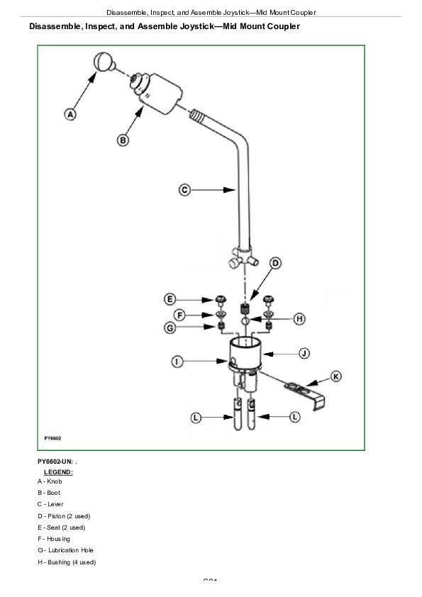
Disassemble, Inspect, and Assemble Joystick—Mid Mount Coupler................601
Disassemble, Inspect and Assemble Mid Mount Control Valve................603
Inspect and Replace Hydraulic Hoses—Mid Mount Coupler................607
Section 80: Miscellaneous Repair................609
Group 05: Front Axle................609
Specification................611
Remove and Install Front Axle — MFWD................612
Group 10: Wheels................609
Specifications................758
Inspect and Replace Front Wheel Bearings................618
Tighten Bolts—Rear Axle (M-20 Stud)................620
Group 15: 3-Point Hitch................609
Specifications................758
Inspect and Repair Fixed Draft Links................623
Inspect and Repair Lift Link (If Equipped)................626
Inspect and Repair Lift Link (If Equipped)................626
Inspect and Repair Adjustable Lift Link (If Equipped)................630
Inspect and Repair Adjustable Lift Link (If Equipped)................630
Inspect and Repair Center Link................632
Group 25: Hood................609
Remove and Install Hood................636
Section 90: Operator Station Repair (OOS)................638
Group 05: Seat and Support................638
Remove and Install Seat and Support (OOS)................640
Disassemble, Inspect and Assemble Seat and Seat Switch................641
Group 06: Center Console................638
Remove Center Console Assembly................645
Install Center Console Assembly................647
Group 10: Roll-Gard™................638
Specifications................758
Remove and Install Roll-Gard™................638
ROPS Serial Number................654
Group 15: Operator Platform................638
Specifications................758
Remove and Install Right-Side Platform and Step................657
Remove and Install Left-Side Platform and Handrail................659
Group 20: Fenders................638
Remove and Install Fenders................664
Group 25: Canopy (If Equipped)................638
Specifications................758
Remove and Install Canopy................668
Section 91: Operator Station Repair (Cab)................670
Group 05: Seat and Support................670
Remove and Install Seat and Support (Cab)................674
Group 10: Control Console and Panel................670
Specifications................758
Remove and Install Right-Side Control Console................677
Remove and Install Left-Side Control Console................679
Remove and Install Center Control Console (TSS Transmission)................681
Remove and Install Center Control Console (PR Transmission)................683
Group 20: Cab Components................670
Essential Tools................753
Service Equipment and Tools................756
Other Material................757
Specifications................758
Remove, Inspect, and Install Cab Interior Recirculating Air Filters................690
Remove, Inspect, and Install Exterior Cab Intake Air Filter................692
Remove and Install Headliner................694
Remove and Install Left-Side Upholstery................697
Remove and Install Right-Side Upholstery................699
Remove and Install Windshield................700
Remove and Install Front Lower Windows................703
Remove and Install Rear Lower Window................705
Remove and Install Rear Upper Window................706
Remove and Install Side Windows................707
Remove and Install Cab Doors................709
Remove and Install Inner Roof for Air Conditioning Housing Repair................712
Remove Cab................724
Install Cab................738
Group 30: Air Conditioning System................670
Essential Tools................753
Service Equipment and Tools................756
Other Material................757
Specifications................758
Adjust A/C Temperature Control Switch................759
Recover/Recycle Air Conditioning Refrigerant................761
Replace Air Conditioning Receiver/Dryer................762
Remove, Inspect, and Install Air Conditioning Condenser................764
Remove, Inspect, and Install Air Conditioning Compressor................767
Test Volumetric Efficiency of Compressor................772
Test Compressor Shaft Seal Leakage................774
Disassemble and Assemble Compressor Clutch................776
Disassemble, Inspect, and Assemble Compressor................778
Check Compressor Clutch Hub Clearance................782
Inspect Compressor Manifold................783
Remove, Inspect, and Install Compressor Relief Valve................784
Remove and Install HVAC Housing Cover................785
Remove Blower Motors................786
Remove Evaporator/Heater Core................787
Leak Test Evaporator/Heater Core................789
Install Evaporator/Heater Core................790
Service Expansion Valve................792
Expansion Valve Bench Test................793
Refrigerant Oil Information................795
Check Compressor Oil Charge................796
Determine Correct Refrigerant Oil Charge................797
Add Refrigerant Oil to System................799
System Information................800
Flush Air Conditioning System................801
Evacuate Air Conditioning System................806
Charge Air Conditioning System................807
Group 35: Heating System................671
Adjust Heater Temperature Control Cable................810
Replace Heater Temperature Control Cable................812
Remove Heater Control Valve................815
Leak Test Heater Control Valve................816
Install Heater Control Valve................817
John Deere Tractors 5055E, 5060E, 5065E, 5075E Repair Service Manual (TM901919)


