Case 580M, 580M Turbo, 580 Super M, 580 Super M+, 590 Super M, 590 Super M+ Loader Factory Service & Shop Manual
Catalog:
Model:
Complete workshop service repair manual with electrical wiring diagrams for Case M Series 1/2/3 Loader Backhoe. It's the same service manual used by dealers that guaranteed to be fully functional and intact without any missing page.
This Case 580M, 580M Turbo, 580 Super M, 580 Super M+, 590 Super M, 590 Super M+ Loader service & repair manual (including maintenance, overhaul, disassembling & assembling, adjustment, tune-up, operation, inspecting, diagnostic & troubleshooting…) is divided into different sections. Each section covers a specific component or system with detailed illustrations. A table of contents is placed at the beginning of each section. Pages are easily found by category, and each page is expandable for great detail. The printer-ready PDF documents work like a charm on all kinds of devices.
“6-41490.pdf”
Case M Series Loader / Backhoe Service Manual; 6-41490; 366 MB; 1,524 pages
Case Series 580M, 580 Super M (580SM) , 590 Super M (590SM) Loader / Backhoe
“6-74432.pdf”
Case M Series 2 Loader / Backhoe Service Manual; Bur 6-74432; 703 MB; 1,713 pages
Case Series 2 580M, 580M Turbo, 580 Super M (580SM), 580 Super M+ (580SM+), 590 Super M (590SM) Loader / Backhoe
“87728449NA.pdf”
Case M Series 3 Loader / Backhoe Service Manual; Bur 6-74432; 284 MB; 1,467 pages
Case 580M, 580 Super M (580SM), 580 Super M+ (580SM+), 590 Super M (590SM), 590 Super M+ (590SM+) Series 3 Loader / Backhoe
“6-75122.pdf”
Electrical Schematic & Hydraulic Schematic for 580M, 580SM, 580SM+, 590SM Series 2 Loader Backhoe
“5-12380.pdf”
Electrical Schematic & Hydraulic Schematic for 580M, 580SM, 580SM+, 590SM, 590SM+ Series 3 Loader Backhoe
“6-20601.pdf”
580M, 580M Turbo, 580 Super M, 590 Super M Series Loader Backhoe Operator's Manual; 315 pages
“87592031.pdf”
580M, 580M Turbo, 580 Super M, 580 Super M+, 590 Super M Series 2 Loader Backhoe Operator's Manual; 304 pages
“84287120.pdf”
580M, 580 Super M, 580 Super M+, 590 Super M, 590 Super M+ Series 3 Loader Backhoe Operator’s Manual; 263 pages
“87657943NA.pdf”
Series 3 Loader Backhoe Operator’s Manual; 260 pages
580M, 580 Super M, 580 Super M+, 590 Super M, 590 Super M+ Series3 (Tier 3) Loader Backhoe
“7-6091 NA.pdf”
580 Super M Loader Backhoe Parts Catalog; 808 pages
“7-9043 NA.pdf”
580 Super M, 580 Super M+ Series 2 Loader Backhoe Parts Catalog; 982 pages; 7-9043 NA, Replaces 7-9042 NA
“87632284NA.pdf”
580 Super M, 580 Super M+ Series 3 Loader Backhoe Parts Catalog; 930 pages
EXCERPT:
SECTION INDEX
POWER TRAIN
Removal and Installation of Power Train Components . . . . . . . . . . . . . . . . . .6000
Standard Transmission Specifications, Pressure Checks, and Troubleshooting . . . . . . . . . . . . . . . . . . . . . . . .6002
Power Shift Transmission Specifications, Pressure Checks and Troubleshooting . . . . . . . . . . . . . . . . . . . . . . .6002
Wheels and Tires . . . . . . . . . . . . . . . . . . . . . . . . . . . . . .6003
Rear Axle and Planetaries - 580M and 580SM . . . . . . . . . . . . . . . . . . . . . . . .6004
Rear Axle and Planetaries - 580SM+, 590SM and 590SM+ . . . . . . . . . . . . . .6004
Standard Transmission . . . . . . . . . . . . . . . . . . . . . . . . . . . . . . . . . . . . . . . . . .6007
Power Shift Transmission . . . . . . . . . . . . . . . . . . . . . . . . . . . . . . . . . . . . . . . .6007
…
MANUAL TRANSMISSION
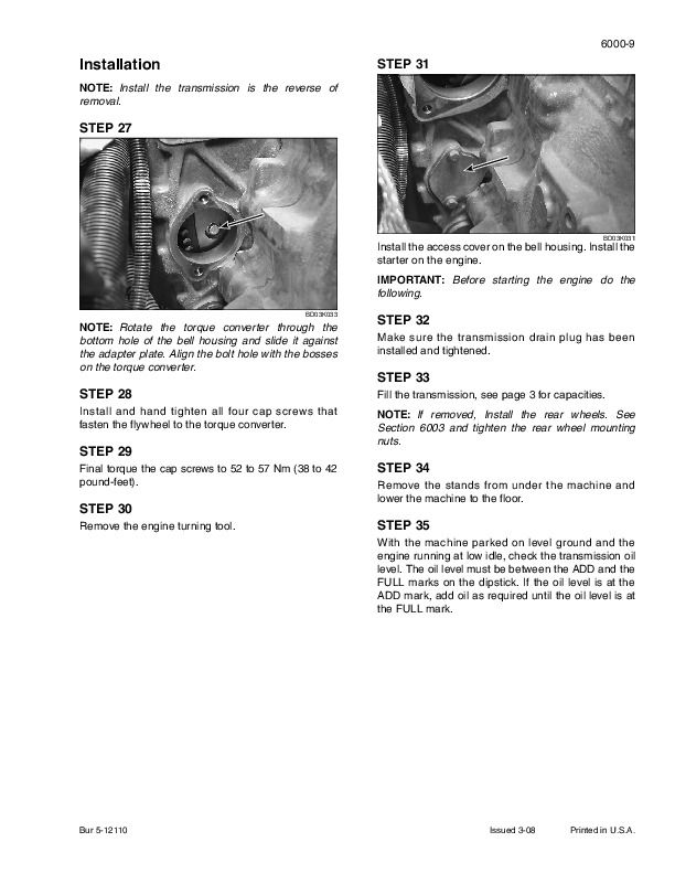
Removal
STEP 1
Park the machine on a level surface. Put the backhoe in the transport position with the stabilizers down. Also put the loader bucket on the floor.
STEP 2
Raise the wheels off the floor high enough to remove the transmission. Put suitable stands under both sides of the machine at the front and rear.
NOTE: The rear wheels can be removed to ease the transmission removal.
STEP 3
Drain the transmission oil.
STEP 4
Disconnect the supply line (1) from the transmission,
disconnect the return line (2) from the transmission.
STEP 5
Disconnect the differential lock hose.
STEP 6
1. FRONT CAB FLOOR MAT
2. CAB FRONT FLOOR PLATE
If equipped, remove the front cab floor mat (1).
Remove the cab front floor plate (2).
STEP 7
1. RETURN SPRING
2. TRANSMISSION GEAR SHIFT LEVER
3. TRANSMISSION SHIFTER MECHANISM
Disconnect the return spring (1) for the shift lever.
Disconnect the transmission gear shift lever (2) from the transmission shifter mechanism (3).
STEP 8
Disconnect the wiring harness connector for the transmission shift solenoid.
STEP 9
Disconnect the wiring harness for the transmission temperature sender.
STEP 10
Disconnect the wiring harness for the SAHR parking brake.
STEP 11
If equipped, disconnect the wiring harness for the four wheel drive solenoid.
STEP 12
Loosen and remove the cap screw and washer (1) for the left rear mounting bracket on front drive shaft guard through the access hole in the fuel tank.
STEP 13
Loosen and remove the bolts, washers, and nuts (2) that fasten the left rear mounting bracket to front drive shaft guard. Remove the left rear mounting bracket.
…


