Doosan DL250 Wheel Loader Factory Service & Shop Manual
Catalog:
Model:
Complete workshop repair service manual with electrical wiring diagrams for Doosan DL250 Wheel Loader. It's the same service manual used by dealers that guaranteed to be fully functional and intact without any missing page.
This Doosan DL250 Wheel Loader service & repair manual (including maintenance, overhaul, disassembling & assembling, adjustment, tune-up, operation, inspecting, diagnostic & troubleshooting…) is divided into different sections. Each section covers a specific component or system with detailed illustrations. A table of contents is placed at the beginning of each section. Pages are easily found by category, and each page is expandable for great detail. The printer-ready PDF documents work like a charm on all kinds of devices.
“K1023773E.pdf”
Doosan DL250 Wheel Loader Shop Manual
K1023773E; Serial Number 5001 and Up; 800 pages
TABLE OF CONTENTS
Safety
Wheel Loader Safety..................... SP000865
Specifications
Specification for DL250.................... SP000866
General Maintenance
General Maintenance Procedures ..................... SP000097
Standard Torques .................... SP000813
Drive Train
Transmission and Torque Converter.................... SP000867
Transmission Error Codes (ZF)...................... SP001056
Front Axle (ZF-MT-L 3085)............................. SP000868
Rear Axle (ZF-MT-L 3075) ............................. SP000869
Drive Shaft ................... SP000870
Brake
Service Brake........................... SP000871
Brake Supply Valve.................... SP000872
Parking Brake .......................... SP000873
Brake Pedal Valve................... SP000874
Accumulator.............................. SP000875
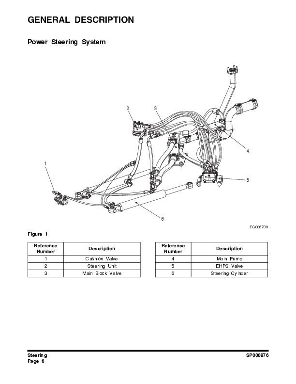
Steering
Steering ..................... SP000876
Cushion Valve.......................... SP000328
Emergency Steering ................... SP000877
Frame
Articulation Center ................... SP000878
Counterweight........................... SP000130
Tank
Oil Tank..................... SP000879
Fuel Tank..................... SP000880
Hydraulics
Cylinders.................... SP001027
Main Pump................... SP001035
Main Control Valve..................... SP000881
Load Isolation System................... SP000882
Cooling System........................ SP000883
Pilot System............................. SP000884
Hydraulic Schematic DL250............................ SP000886
Electrical System
Air Conditioner ......................... SP001211
Electrical System ..................... SP000924
Electrical Schematic DL200/ DL250..................... SP000925
…
EXCERPT:
Accumulators are solidly constructed to resist the high operating pressures of the fluids they contain. There are only three main moving parts: a valve assembly at the top allows adding or expelling gas from the compressible, precharged upper chamber; a valve assembly at the bottom of the accumulator for passing hydraulic fluid in and out, and an elastic diaphragm to separate the two chambers.
The flexible diaphragm changes shape to conform to the changing pressures and volumes of the two fluids in the upper and lower chambers.
There are six possible positions the diaphragm can be in and they are as follows:
1. With no gas charge in the upper chamber 0 bar (0 psi, empty) and no oil in the bottom 0 bar (0 psi, dry) the elastic diaphragm hangs loosely.
…


