Bobcat T250 Compact Track Loader Factory Service & Shop Manual
Catalog:
Model:
Complete workshop repair service manual with electrical wiring diagrams for Bobcat T250 Compact Track Loader. It's the same service manual used by dealers that guaranteed to be fully functional and intact without any missing page.
This Bobcat T250 Compact Track Loader service & repair manual (including maintenance, overhaul, disassembling & assembling, adjustment, tune-up, operation, inspecting, diagnostic & troubleshooting…) is divided into different sections. Each section covers a specific component or system with detailed illustrations. A table of contents is placed at the beginning of each section. Pages are easily found by category, and each page is expandable for great detail. The printer-ready PDF documents work like a charm on all kinds of devices.
6902450 (9-07) - T250 Turbo, T250 Turbo High Flow Operation & Maintenance Manual.pdf
6902451 (3-06) - T250 Turbo, T250 Turbo High Flow Service Manual.pdf
6902702 (12-06) - T250 Turbo, T250 Turbo High Flow Operation & Maintenance Manual.pdf
6902724 (2-06) - T250 Turbo, T250 Turbo High Flow Service Manual.pdf
6904162 (10-07) - T250 Compact Track Loader Operation & Maintenance Manual.pdf
6904164 (3-09) - T250 Compact Track Loader Service Manual.pdf
6904182 (12-06) - T250 Turbo, T250 Turbo High Flow Operation & Maintenance Manual.pdf
6986682 (3-09) - T250 Compact Track Loader Service Manual.pdf
6986974 (4-08) - T250 Compact Track Loader Operation & Maintenance Manual.pdf
6987003 (11-10) - T250 Compact Track Loader Operation & Maintenance Manual.pdf
6987044 (2-11) - T250 Compact Track Loader Service Manual.pdf
6987044 (6-10) - T250 Compact Track Loader Service Manual.pdf
EXCERPT:
CONTENTS
FOREWORD. . . . . . . II
SAFETY INSTRUCTIONS . . . . . V
FIRE PREVENTION . . . . . . . . . VII
SERIAL NUMBER LOCATIONS . . . . . . . . . . IX
DELIVERY REPORT. . . . . . . . . . X
LOADER IDENTIFICATION . . . .XI
SAFETY & MAINTENANCE . . . . . . . . . . 10-01
HYDRAULIC SYSTEM . . . . . 20-01
HYDROSTATIC SYSTEM . . . 30-01
DRIVE SYSTEM . . . . . . . . . . 40-01
MAINFRAME. . . . 50-01
ELECTRICAL SYSTEM & ANALYSIS. . . 60-01
ENGINE SERVICE . . . . . . . . 70-01
HEATING, VENTILATION, AIR CONDITIONING . . . 80-01
SPECIFICATIONS. . . . . . SPEC-01
…
DRIVE BELT
Description
The drive belt connects the engine to the hydrostatic pumps. The drive belt is tighten by a spring tensioner and is covered by a shield to protect operator.
The drive belt is located on the flywheel side of the engine by the battery.
Shield Removal And Installation
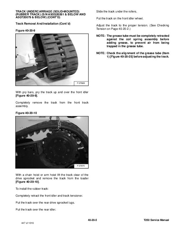
Figure 30-50-1
Stop the engine.
Open the rear door.
Remove the bolt (Item 1) [Figure 30-50-1] from the cable bracket.
Move the cable to allow removal of the drive shield.
Figure 30-50-2
Remove the three drive belt shield clips (Item 1) [Figure 30-50-2].
…


