Caterpillar 3114, 3116 and 3126 Engines Factory Service & Shop Manual
Catalog:
Model:
Complete workshop & service manual with electrical wiring diagrams for Caterpillar 3114, 3116, 3126 Diesel Engines. It's the same service manual used by dealers that guaranteed to be fully functional and intact without any missing page.
This Caterpillar 3114, 3116 and 3126 Diesel Engines service & repair manual (including maintenance, overhaul, disassembling & assembling, adjustment, tune-up, operation, inspecting, diagnostic & troubleshooting…) is divided into different sections. Each section covers a specific component or system with detailed illustrations. A table of contents is placed at the beginning of each section. Pages are easily found by category, and each page is expandable for great detail. The printer-ready PDF documents work like a charm on all kinds of devices.
2,121 pages, bookmarked, Searchable, Printable, high quality PDF
MANUAL LIST:
KENR9511 - Schematic - Marine Multi-Station Control System II Electrical System - Typical Dual Engine Installation
RENR1377 - Systems Operation (Electric Protection System Energize-To-Run for Generator Set, Industrial & Marine Diesel Engines)
RENR1377 - Testing & Adjusting (Electric Protection System Energize-To-Run for Generator Set, Industrial & Marine Diesel Engines)
RENR7651 - Systems Operation (Marine Multi-Station Control System)
RENR7651 - Testing & Adjusting (Marine Multi-Station Control System)
RENR7651 - Troubleshooting (Marine Multi-Station Control System)
RENR7893 - Marine Multi-Station Control System Electrical System - Typical Single Engine Installation
RENR7893 - Schematic - Marine Multi-Station Control System Electrical System - Typical Single Engine Installation
RENR7929 - Schematic - Marine Multi-Station Control System Electrical System - Typical Dual Engine Installation
SEGV3008 - Systems Operation (Fundamentals Electrical System for All Caterpillar Products)
SENR3581 - Disassembly & Assembly (37-MT, 41-MT, 42-MT Series Starting Motors)
SENR3581 - Systems Operation (37-MT, 41-MT, 42-MT Series Starting Motors)
SENR3581 - Testing & Adjusting (37-MT, 41-MT, 42-MT Series Starting Motors)
SENR3581 - Troubleshooting (37-MT, 41-MT, 42-MT Series Starting Motors)
SENR3947 - Disassembly & Assembly (Supplement for 3116 & 3126 Marine Engine)
SENR3947 - Specifications (Supplement for 3116 & 3126 Marine Engine)
SENR3981 - Schematic - Fluid Power & Electrical Graphic Symbols
SENR3981 - Schematic - Fluid Power and Electrical Graphic Symbols
SENR4695 - Disassembly & Assembly (Model MG 5050 Marine Transmission)
SENR6454 - Disassembly and Assembly (3114, 3116 and 3126 MUI Engine Governors)
SENR6454 - Specifications (3114, 3116 and 3126 MUI Engine Governors)
SENR6454 - Systems Operation (3114, 3116 and 3126 MUI Engine Governors)
SENR6454 - Testing and Adjusting (3114, 3116 and 3126 MUI Engine Governors)
SENR6502 - Troubleshooting (3114, 3116 & 3126 Engines)
SENR7508 - Disassembly & Assembly (30SI Series & 34SI Series Alternator)
SENR7508 - Systems Operation (30SI Series & 34SI Series Alternator)
SENR7508 - Testing & Adjusting (30SI Series & 34SI Series Alternator)
SENR9518 - Disassembly and Assembly (3114, 3116 & 3126 Engines)
SENR9557 - Specifications (3114, 3116 & 3126 Industrial, Marine & Generator Set Engines)
SENR9558 - Systems Operation (3114, 3116 & 3126 Industrial, Marine & Generator Set Engines)
SENR9558 - Testing & Adjusting (3114, 3116 & 3126 Industrial, Marine & Generator Set Engines)
SENR3581 - Specifications (37-MT, 41-MT, 42-MT Series Starting Motors).pdf
SENR3947 - Systems Operation (Supplement for 3116 & 3126 Marine Engine).pdf
SENR3947 - Testing & Adjusting (Supplement for 3116 & 3126 Marine Engine).pdf
SENR4695 - General Service Information - Marine Transmission (Model MG 5050 Marine Transmission).pdf
SENR4695 - Systems Operation (Model MG 5050 Marine Transmission).pdf
SENR4695 - Troubleshooting - Introduction (Model MG 5050 Marine Transmission).pdf
SENR7508 - Specifications (30SI Series & 34SI Series Alternator).pdf
SENR3130 - Torque Specifications
UENR3262 - Disassembly & Assembly - Seal Installation
1. CATERPILLAR - 3116 - FUEL SYSTEM - DIESEL -1994 GMC C Series - C7.pdf
2. CATERPILLAR - 3116 -1994 GMC C Series - C7.pdf
SEBF9050 - Applied Failure Analysis - Engine Valve Failure Modes{1100, 1105}.pdf
SEBU6875 - Owner's Manual (Caterpillar Driver Information Display).pdf
SENR2995 - Product Safety.pdf
SENR3130 - Specifications (Torque Specifications for All Caterpillar Products).pdf
...
.
bonus_matrial
1. CATERPILLAR - 3116 - FUEL SYSTEM - DIESEL -1994 GMC C Series - C7.pdf
2. CATERPILLAR - 3116 -1994 GMC C Series - C7.pdf
SEBF9050 - Applied Failure Analysis - Engine Valve Failure Modes{1100, 1105}.pdf
SEBU6875 - Owner's Manual (Caterpillar Driver Information Display).pdf
SENR2995 - Product Safety.pdf
SENR3130 - Specifications (Torque Specifications for All Caterpillar Products).pdf
SENR3130 - Torque Specifications
Air Brake Fittings.pdf
Air Conditioning Fittings.pdf
Bulkhead Nuts.pdf
English (SAE) Fasteners.pdf
Flare Fittings.pdf
General Information.pdf
Ground Engaging Tool (G.E.T.) Fasteners.pdf
Hose Clamps.pdf
Installation of Fittings.pdf
Metric (ISO) Fasteners.pdf
Miscellaneous Fittings.pdf
O-Ring Face Seal Fittings.pdf
Plugs.pdf
Straight Thread O-Ring Fittings.pdf
Tapered Pipe Thread Fittings.pdf
UENR3262 - Disassembly & Assembly - Seal Installation
Duo-Cone Seals - Install.pdf
Lip Type Seals - Install.pdf
O-Ring Seals - Install - RADIAL, FITTING ASSEMBLY O-RINGS & OTHER O-RING APPLICATIONS.pdf
KENR9511 - Schematic - Marine Multi-Station Control System II Electrical System - Typical Dual Engine Installation
Collage.pdf
Main.pdf
KENR9511 - Schematic - Marine Multi-Station Control System II Electrical System - Typical Dual Engine Installation.pdf
RENR1377 - Systems Operation (Electric Protection System Energize-To-Run for Generator Set, Industrial & Marine Diesel Engines)
Abbreviations and Symbols.pdf
ETR Component Descriptions.pdf
ETR Introduction.pdf
ETR Junction Box-Switchgear Not Required (OP,WT,OS).pdf
ETR Junction Box-Switchgear Not Required (OP,WT).pdf
ETR Junction Box-Switchgear Required (OP,WT,OS).pdf
Junction Box and Enclosure Group.pdf
RENR1377 - Systems Operation (Electric Protection System Energize-To-Run for Generator Set, Industrial & Marine Diesel Engines).pdf
RENR1377 - Testing & Adjusting (Electric Protection System Energize-To-Run for Generator Set, Industrial & Marine Diesel Engines)
Crank Terminate Speed Calibration.pdf
Diode Test.pdf
Electric Protection System Functional Test.pdf
Engine Oil Pressure Switch Test.pdf
General Testing and Adjusting Information.pdf
General Troubleshooting Information.pdf
Magnetic Pickup Test.pdf
Oil Step Speed Calibration.pdf
Overspeed Calibration.pdf
Overspeed Verification Test.pdf
Slave Relay Test.pdf
Troubleshooting the ETR Full Protective System (OP, WT, OS).pdf
Troubleshooting the ETR Partial Protection System (OP, WT).pdf
Water Temperature Contactor Switch Test.pdf
RENR1377 - Testing & Adjusting (Electric Protection System Energize-To-Run for Generator Set, Industrial & Marine Diesel Engines).pdf
RENR7651 - Systems Operation (Marine Multi-Station Control System)
Data Link.pdf
General Information.pdf
Junction Box.pdf
Marine Power Display.pdf
Operator Controls.pdf
RENR7651 - Systems Operation (Marine Multi-Station Control System).pdf
RENR7651 - Testing & Adjusting (Marine Multi-Station Control System)
Electrical Connector - Inspect.pdf
Glossary of Terms.pdf
Parameter - Program.pdf
RENR7651 - Testing & Adjusting (Marine Multi-Station Control System).pdf
RENR7651 - Troubleshooting (Marine Multi-Station Control System)
Active Station - Test.pdf
Button Panel - Test.pdf
Connector Locations.pdf
Control Head - Calibrate.pdf
Control Panel - Test.pdf
Data Link (Engine Monitoring System and Engine Vision) - Test.pdf
Data Link (Marine Power Display) - Test.pdf
Diagnostic Code List.pdf
E881 Multiple Stations on Master Control Data Link.pdf
ECM CID 0091 - FMI 08.pdf
ECM CID 0091 - FMI 13.pdf
ECM CID 0116 - FMI 00.pdf
ECM CID 0168 - FMI 00.pdf
ECM CID 0168 - FMI 01.pdf
ECM CID 0168 - FMI 02.pdf
ECM CID 1383 - FMI 11.pdf
Electronic Service Tool Will Not Communicate with PCP.pdf
Engine Cranks but Will Not Start.pdf
Gear Lockout - Test.pdf
General Information.pdf
PCP CID 0369 - FMI 07.pdf
PCP CID 0700 - FMI 02.pdf
PCP CID 0718 - FMI 07.pdf
PCP CID 1326 - FMI 09.pdf
PCP CID 1440 - FMI 03.pdf
PCP CID 1440 - FMI 04.pdf
PCP CID 1440 - FMI 07.pdf
PCP CID 1440 - FMI 08.pdf
PCP CID 1815 - FMI 04.pdf
PCP CID 1815 - FMI 12.pdf
PCP CID 1815 - FMI 13.pdf
PCP CID 1816 - FMI 09.pdf
PCP CID 1817 - FMI 09.pdf
PCP CID 1821 - FMI 09.pdf
PCP CID 1822 - FMI 09.pdf
Service Tools.pdf
Slow Vessel Mode - Test.pdf
Station Does Not Transfer.pdf
Switch Inputs Not Working.pdf
Troll Does Not Function.pdf
Using Caterpillar Electronic Technician (ET) to Determine Diagnostic Codes.pdf
RENR7651 - Troubleshooting (Marine Multi-Station Control System).pdf
RENR7893 - Marine Multi-Station Control System Electrical System - Typical Single Engine Installation
Collage.pdf
Main.pdf
RENR7893 - Marine Multi-Station Control System Electrical System - Typical Single Engine Installation.pdf
RENR7893 - Schematic - Marine Multi-Station Control System Electrical System - Typical Single Engine Installation
Collage.pdf
Main.pdf
RENR7893 - Schematic - Marine Multi-Station Control System Electrical System - Typical Single Engine Installation.pdf
RENR7929 - Schematic - Marine Multi-Station Control System Electrical System - Typical Dual Engine Installation
Collage.pdf
Main.pdf
RENR7929 - Schematic - Marine Multi-Station Control System Electrical System - Typical Dual Engine Installation.pdf
SEGV3008 - Systems Operation (Fundamentals Electrical System for All Caterpillar Products)
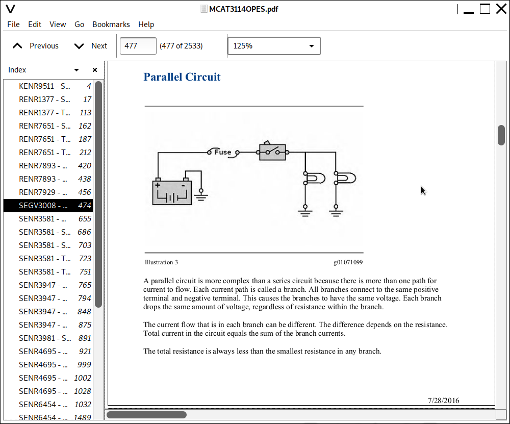
Basic Circuit Theory.pdf
Basic Electrical Components.pdf
Battery.pdf
Charging System.pdf
Circuit Voltage.pdf
Electrical Measurement.pdf
Electrical Schematic.pdf
Electricity - How It Works.pdf
Magnetism.pdf
Ohms Law.pdf
Solid State Electrical Components.pdf
Starting System.pdf
SEGV3008 - Systems Operation (Fundamentals Electrical System for All Caterpillar Products).pdf
SENR3581 - Disassembly & Assembly (37-MT, 41-MT, 42-MT Series Starting Motors)
General Information.pdf
Starting Motor - Assemble - 37-MT and 41-MT.pdf
Starting Motor - Assemble - 42-MT.pdf
Starting Motor - Disassemble - 37-MT and 41-MT.pdf
Starting Motor - Disassemble - 42-MT.pdf
SENR3581 - Disassembly & Assembly (37-MT, 41-MT, 42-MT Series Starting Motors).pdf
SENR3581 - Specifications (37-MT, 41-MT, 42-MT Series Starting Motors).pdf
SENR3581 - Systems Operation (37-MT, 41-MT, 42-MT Series Starting Motors)
Component Description.pdf
General Information.pdf
Normal Operation.pdf
SENR3581 - Systems Operation (37-MT, 41-MT, 42-MT Series Starting Motors).pdf
SENR3581 - Testing & Adjusting (37-MT, 41-MT, 42-MT Series Starting Motors)
Brush and Brush Holder - Check.pdf
No Load - Test.pdf
Pinion Clearance - Adjust.pdf
Starting Motor Solenoid - Test.pdf
SENR3581 - Testing & Adjusting (37-MT, 41-MT, 42-MT Series Starting Motors).pdf
SENR3581 - Troubleshooting (37-MT, 41-MT, 42-MT Series Starting Motors)
Engine Does Not Crank with Starting Motor On and Pinion Engaging Ring Gear.pdf
General Information.pdf
Service Tools.pdf
Starting Motor Does Not Turn or Turns Slowly.pdf
SENR3581 - Troubleshooting (37-MT, 41-MT, 42-MT Series Starting Motors).pdf
SENR3947 - Disassembly & Assembly (Supplement for 3116 & 3126 Marine Engine)
Alternator.pdf
Expansion Tank.pdf
Heat Exchanger.pdf
Oil Cooler (Marine Transmission Gear).pdf
Raw Water Pump.pdf
Watercooled Turbocharger-.pdf
Watercooled Turbocharger.pdf
Water Temperature Regulator Housing-.pdf
Water Temperature Regulator Housing.pdf
Water Temperature Regulator.pdf
SENR3947 - Disassembly & Assembly (Supplement for 3116 & 3126 Marine Engine).pdf
SENR3947 - Specifications (Supplement for 3116 & 3126 Marine Engine)
Air Inlet Heater Group.pdf
Alternator.pdf
Auxiliary Water Pump.pdf
Circuit Breaker.pdf
Contactor Group.pdf
Control Relay.pdf
Electric Starting Motor.pdf
Electric Starting Motor Solenoid.pdf
Heat Exchanger Group (Sea Water).pdf
Hydraulic Pump Drive Mounting Group (Front).pdf
Instrument Panel Group.pdf
Introduction.pdf
Jacket Water Heater.pdf
Junction Box.pdf
Magnetic Starter Switch Assembly.pdf
Oil Pressure Sender.pdf
Power Take-Off Group (Front).pdf
Regulator.pdf
Sensors _Low Coolant Level.pdf
Water Temperature Regulator.pdf
Water Temperature Sender.pdf
SENR3947 - Specifications (Supplement for 3116 & 3126 Marine Engine).pdf
SENR3947 - Systems Operation (Supplement for 3116 & 3126 Marine Engine).pdf
SENR3947 - Testing & Adjusting (Supplement for 3116 & 3126 Marine Engine).pdf
SENR3981 - Schematic - Fluid Power & Electrical Graphic Symbols
Electrical Power Graphic Symbols.pdf
Fluid Power Graphic Symbols.pdf
SENR3981 - Schematic - Fluid Power & Electrical Graphic Symbols.pdf
SENR4695 - Disassembly & Assembly (Model MG 5050 Marine Transmission)
Alignment.pdf
Assembly Of Forward Clutch.pdf
Assembly Of Front Half Housing.pdf
Assembly Of Selector Valve Assembly.pdf
Assembly Of Trolling Valve Unit.pdf
Cleaning And Inspection of Clutch Assembly.pdf
Clutch And Output Shaft Groups.pdf
Disassembly And Assembly.pdf
Disassembly Of Forward Or Reverse Clutch.pdf
Disassembly Of Front Half Housing.pdf
Disassembly Of Rear Half Housing.pdf
Disassembly of Reverse Clutch.pdf
Disassembly Of Selector Valve.pdf
Disassembly Of Trolling Valve Unit.pdf
General.pdf
Installing Forward And Reverse Clutch Assemblies.pdf
Introduction.pdf
Prior To Installation.pdf
Removal Of Transmission Unit.pdf
Transmission Installation.pdf
Unit Assembly And Installation.pdf
SENR4695 - Disassembly & Assembly (Model MG 5050 Marine Transmission).pdf
SENR4695 - General Service Information - Marine Transmission (Model MG 5050 Marine Transmission).pdf
SENR4695 - Systems Operation (Model MG 5050 Marine Transmission).pdf
SENR4695 - Troubleshooting - Introduction (Model MG 5050 Marine Transmission).pdf
SENR6454 - Disassembly and Assembly (3114, 3116 and 3126 MUI Engine Governors)
Governor (Type I) - Assemble.pdf
Governor (Type I) - Disassemble.pdf
Governor (Type II) - Assemble.pdf
Governor (Type II) - Disassemble.pdf
Governor (Type III) - Assemble.pdf
Governor (Type III) - Disassemble.pdf
Governor (Type IV) - Assemble.pdf
Governor (Type IV) - Disassemble.pdf
Governor (Type V) - Assemble.pdf
Governor (Type V) - Disassemble.pdf
Governor (Type VI) - Assemble.pdf
Governor (Type VI) - Disassemble.pdf
Governor (Type VII) - Assemble.pdf
Governor (Type VII) - Disassemble.pdf
SENR6454 - Disassembly and Assembly (3114, 3116 and 3126 MUI Engine Governors).pdf
SENR6454 - Specifications (3114, 3116 and 3126 MUI Engine Governors)
Governor Identification - Introduction.pdf
Governor Performance Data.pdf
Governor (Type III).pdf
Governor (Type II).pdf
Governor (Type I).pdf
Governor (Type IV).pdf
Governor (Type VII).pdf
Governor (Type VI).pdf
Governor (Type V).pdf
Specification.pdf
SENR6454 - Specifications (3114, 3116 and 3126 MUI Engine Governors).pdf
SENR6454 - Systems Operation (3114, 3116 and 3126 MUI Engine Governors)
Dashpot (Types I, III, IV, V, VI, and VII).pdf
Dual Horsepower (Type VII).pdf
Dual Horsepower (Type VI).pdf
Fuel Ratio Control (Types I and IV).pdf
Fuel Ratio Control (Types V, VI, and VII).pdf
Fuel Shutoff Solenoid.pdf
Fuel Transfer Pump.pdf
Governor Bias Spring (Most Types IV, V, and VI).pdf
Governor Bumper Spring (Some Type IV).pdf
Governor Limiting Circuit (Types I, II, III, and IV).pdf
Governor Limiting Circuit (Types V, VI, and VII).pdf
Governor Servo (Types I, III, IV, V, VI, and VII).pdf
Governor Speed Circuit.pdf
Torque Limiter Device (Some Type V).pdf
SENR6454 - Systems Operation (3114, 3116 and 3126 MUI Engine Governors).pdf
SENR6454 - Testing and Adjusting (3114, 3116 and 3126 MUI Engine Governors)
Governor (Type III) - Check.pdf
Governor (Types I, II, and Some III) - Adjust.pdf
Governor (Types I, II, IV, and V) - Check.pdf
Governor (Types IV and Some III) - Adjust.pdf
Governor (Type V) - Adjust.pdf
Governor (Type VI) - Adjust.pdf
Governor (Type VI) - Check.pdf
Governor (Type VII) - Adjust.pdf
Governor (Type VII) - Check.pdf
Installation of Governor on 1U7326 Governor Calibration Bench.pdf
Prepare Calibration Bench for Test Procedure.pdf
Setting the Governor Load Stop Dimension for More Than 9.00 mm.pdf
Throttle Lever Orientation (Types IV, V, VI, VII, and Some III) - Check.pdf
Throttle Lever (Types IV, V, VI, VII, and Some III) - Install.pdf
Throttle Lever (Types IV, V, VI, VII, and Some III) - Remove.pdf
SENR6454 - Testing and Adjusting (3114, 3116 and 3126 MUI Engine Governors).pdf
SENR6502 - Troubleshooting (3114, 3116 & 3126 Engines)
Air in Fuel.pdf
Air Inlet Heater - If Equipped.pdf
Alternator Charge Rate Is High.pdf
Alternator Charge Rate Is Low.pdf
Alternator Noise.pdf
Alternator Will Not Charge.pdf
Coolant in Engine Oil.pdf
Coolant Temperature Above Normal.pdf
Coolant Temperature Below Normal.pdf
Engine Cranks but Will Not Start.pdf
Engine Has Early Wear.pdf
Engine Misfires, Knocks, or Is Unstable (at Idle Only).pdf
Engine Misfires, Runs Rough or Is Unstable.pdf
Engine Oil in Cooling System.pdf
Engine Overspeeds on Start.pdf
Engine Stalls at Low RPM.pdf
Engine Vibration.pdf
Engine Will Not Crank.pdf
Excessive Black Smoke.pdf
Excessive Blue Smoke.pdf
Excessive Engine Oil Consumption.pdf
Excessive Fuel Consumption.pdf
Excessive Valve Lash.pdf
Excessive White Smoke.pdf
Exhaust Temperature Is Too High.pdf
Fuel in Cooling System.pdf
Fuel in Engine Oil.pdf
Fuel Injection Control Linkage.pdf
Fuel Quality.pdf
Fuel Ratio Control.pdf
Fuel Transfer Pump.pdf
Governor Instability.pdf
Little or No Valve Lash.pdf
Loss of Coolant.pdf
Low Engine Oil Pressure.pdf
Low Power.pdf
Mechanical Noise (Knock) in Engine.pdf
Noise Coming from Cylinder.pdf
Soot in Inlet Manifold.pdf
Unit Injector Cranking Rack Position.pdf
Unit Injector Misfire.pdf
Unit Injector.pdf
Valve Train Noise.pdf
SENR6502 - Troubleshooting (3114, 3116 & 3126 Engines).pdf
SENR7508 - Disassembly & Assembly (30SI Series & 34SI Series Alternator)
Alternator - Assemble.pdf
Alternator - Disassemble.pdf
SENR7508 - Disassembly & Assembly (30SI Series & 34SI Series Alternator).pdf
SENR7508 - Specifications (30SI Series & 34SI Series Alternator).pdf
SENR7508 - Systems Operation (30SI Series & 34SI Series Alternator)
Component Description.pdf
General Information.pdf
Normal Operation.pdf
SENR7508 - Systems Operation (30SI Series & 34SI Series Alternator).pdf
SENR7508 - Testing & Adjusting (30SI Series & 34SI Series Alternator)
Component - Test.pdf
General Information.pdf
Initial Troubleshooting Procedure.pdf
T1 Alternator Output - Test.pdf
T2 Electrical System Current - Test.pdf
T3 Charging System - Test.pdf
T4 Alternator Drive System - Check.pdf
T5 Alternator Current - Test.pdf
T6 Residual Magnetism Restoration.pdf
T7 Identifying Source of Current Draw - Test.pdf
T8 Alternator Overcharging - Test.pdf
SENR7508 - Testing & Adjusting (30SI Series & 34SI Series Alternator).pdf
SENR9518 - Disassembly and Assembly (3114, 3116 & 3126 Engines)
Aftercooler - Install.pdf
Aftercooler - Remove.pdf
Air Compressor Drive Gear - Install.pdf
Air Compressor - Remove and Install.pdf
Alternator - Remove and Install.pdf
Auxiliary Water Pump - Assemble - Type 2.pdf
Auxiliary Water Pump - Disassemble - Type 2.pdf
Auxiliary Water Pump - Install.pdf
Auxiliary Water Pump - Remove.pdf
Bearing Clearance - Check.pdf
Belt Tensioner - Remove and Install.pdf
Belt Tightener - Install.pdf
Belt Tightener - Remove.pdf
Camshaft Bearings - Remove and Install.pdf
Camshaft Gear - Remove and Install.pdf
Camshaft - Install.pdf
Camshaft - Remove.pdf
Crankcase Breather - Remove and Install.pdf
Crankshaft Front Seal - Install.pdf
Crankshaft Front Seal - Remove.pdf
Crankshaft Gear - Remove and Install.pdf
Crankshaft - Install.pdf
Crankshaft Main Bearings - Install.pdf
Crankshaft Main Bearings - Remove.pdf
Crankshaft Rear Seal Carrier - Remove and Install.pdf
Crankshaft Rear Seal - Install.pdf
Crankshaft Rear Seal - Remove.pdf
Crankshaft - Remove.pdf
Crankshaft Wear Sleeve (Rear) - Install.pdf
Crankshaft Wear Sleeve (Rear) - Remove - If Equipped.pdf
Cylinder Head - Install.pdf
Cylinder Head - Remove.pdf
Electric Starting Motor - Remove and Install .pdf
Engine Balancer Shaft - Remove and Install.pdf
Engine Lifting Bracket - Remove and Install.pdf
Engine Oil Cooler Bypass Valve - Remove and Install.pdf
Engine Oil Cooler - Install.pdf
Engine Oil Cooler - Remove.pdf
Engine Oil Filter Base - Assemble.pdf
Engine Oil Filter Base - Disassemble.pdf
Engine Oil Filter Base - Install.pdf
Engine Oil Filter Base - Remove.pdf
Engine Oil Filter Bypass Valve - Remove and Install.pdf
Engine Oil Pressure Sensor - Remove and Install.pdf
Engine Oil Pump - Assemble.pdf
Engine Oil Pump - Disassemble.pdf
Engine Oil Pump - Install.pdf
Engine Oil Pump - Remove.pdf
Ether Atomizer - Remove and Install.pdf
Exhaust Manifold - Remove and Install.pdf
Flywheel Housing - Remove and Install .pdf
Flywheel - Install.pdf
Flywheel - Remove.pdf
Front Cover - Install.pdf
Front Cover - Remove.pdf
Fuel Filter Base - Remove and Install.pdf
Fuel Injection Control Linkage - Install.pdf
Fuel Injection Control Linkage - Remove.pdf
Fuel Priming Pump and Primary Fuel Filter - Remove and Install.pdf
Fuel Shutoff Solenoid - Remove and Install.pdf
Fuel Transfer Pump - Install.pdf
Fuel Transfer Pump - Remove.pdf
Gear Group (Front) - Install.pdf
Gear Group (Front) - Remove.pdf
Governor - Install.pdf
Governor - Remove.pdf
Housing (Front) - Install.pdf
Housing (Front) - Remove.pdf
Inlet and Exhaust Valve Guides - Remove and Install.pdf
Inlet and Exhaust Valve Seat Inserts - Remove and Install.pdf
Inlet and Exhaust Valves - Remove and Install.pdf
Inlet Manifold - Install.pdf
Inlet Manifold - Remove.pdf
Lifter Group - Remove and Install.pdf
Piston Cooling Jets - Remove and Install.pdf
Pistons and Connecting Rods - Assemble.pdf
Pistons and Connecting Rods - Disassemble.pdf
Pistons and Connecting Rods - Install.pdf
Pistons and Connecting Rods - Remove.pdf
Rocker Shaft and Pushrod - Install.pdf
Rocker Shaft and Pushrod - Remove.pdf
Rocker Shaft - Assemble.pdf
Rocker Shaft - Disassemble.pdf
Turbocharger - Install.pdf
Turbocharger - Remove.pdf
Unit Injector - Install.pdf
Unit Injector - Remove.pdf
Unit Injector Sleeve - Install.pdf
Unit Injector Sleeve - Remove.pdf
Valve Mechanism Cover - Remove and Install.pdf
Vibration Damper and Pulley - Remove and Install.pdf
Water Pump - Assemble.pdf
Water Pump - Disassemble.pdf
Water Pump - Install.pdf
Water Pump - Remove.pdf
Water Temperature Regulator Housing - Remove and Install.pdf
Water Temperature Regulator - Remove and Install.pdf
SENR9518 - Disassembly and Assembly (3114, 3116 & 3126 Engines).pdf
SENR9557 - Specifications (3114, 3116 & 3126 Industrial, Marine & Generator Set Engines)
Accessory Drive - Splined.pdf
Aftercooler.pdf
Air Inlet Heater.pdf
Alternator and Regulator.pdf
Balancer Group - 3114 Engine Only.pdf
Belt Tension Chart.pdf
Belt Tensioner-.pdf
Belt Tensioner.pdf
Camshaft.pdf
Connecting Rod Bearing Journal.pdf
Connecting Rod.pdf
Crankcase Breather.pdf
Crankshaft.pdf
Crankshaft Pulley.pdf
Crankshaft Seals.pdf
Cylinder Block Cover Group.pdf
Cylinder Block.pdf
Cylinder Head.pdf
Cylinder Head Valves.pdf
Electric Starting Motor.pdf
Engine Design.pdf
Engine Oil Filter Base.pdf
Engine Oil Pressure.pdf
Engine Oil Pump.pdf
Engine to Transmission Adapter.pdf
Ether Starting Aid.pdf
Exhaust Elbow.pdf
Exhaust Manifold.pdf
Fan Drive.pdf
Flywheel and Flywheel Housing Runout.pdf
Flywheel Housing.pdf
Flywheel.pdf
Front Housing and Covers.pdf
Fuel Filter and Water Separator.pdf
Fuel Filter Base.pdf
Fuel Filter Lines.pdf
Fuel Filter (Primary).pdf
Fuel Injection Control Linkage.pdf
Fuel Shutoff Solenoid.pdf
Fuel Transfer Pump.pdf
Gear Group (Front).pdf
Governor.pdf
Jacket Water Heater.pdf
Magnetic Pickup.pdf
Main Bearing Journal.pdf
Piston and Rings.pdf
Piston Cooling Jet.pdf
Rear Power Take-Off (RPTO).pdf
Rear Seal Carrier - If Equipped.pdf
Turbocharger.pdf
Unit Injector Mechanism.pdf
Unit Injector.pdf
Valve Mechanism Cover.pdf
Valve Rocker Arms and Lifters.pdf
Vibration Damper and Pulley.pdf
Water Pump.pdf
Water Temperature Regulator.pdf
SENR9557 - Specifications (3114, 3116 & 3126 Industrial, Marine & Generator Set Engines).pdf
SENR9558 - Systems Operation (3114, 3116 & 3126 Industrial, Marine & Generator Set Engines)
Air Inlet and Exhaust System.pdf
Basic Engine.pdf
Cooling System.pdf
Electrical System.pdf
Fuel System.pdf
General Information.pdf
Lubrication System.pdf
SENR9558 - Systems Operation (3114, 3116 & 3126 Industrial, Marine & Generator Set Engines).pdf
SENR9558 - Testing & Adjusting (3114, 3116 & 3126 Industrial, Marine & Generator Set Engines)
Air in Fuel - Test.pdf
Air Inlet and Exhaust System - Inspect.pdf
Battery - Test.pdf
Charging System - Test.pdf
Compression - Test.pdf
Connecting Rod Bearings - Inspect.pdf
Cooling System - Check - Overheating.pdf
Cooling System - Inspect.pdf
Cooling System - Test.pdf
Cylinder Block - Inspect.pdf
Electric Starting System - Test.pdf
Engine Crankcase Pressure (Blowby) - Test.pdf
Engine Oil Pressure - Test.pdf
Engine Speed - Check.pdf
Engine Valve Lash - InspectAdjust.pdf
Excessive Bearing Wear - Inspect.pdf
Excessive Engine Oil Consumption - Inspect.pdf
Exhaust Temperature - Test.pdf
Finding Top Center Position for No. 1 Piston.pdf
Flywheel Housing - Inspect.pdf
Flywheel - Inspect.pdf
Fuel Quality - Test.pdf
Fuel Ratio Control - Adjust.pdf
Fuel System - Inspect.pdf
Fuel System Pressure - Test.pdf
Fuel System - Prime.pdf
Fuel Timing Dimension - Adjust.pdf
Gear Group (Front) - Time.pdf
Governor - Adjust.pdf
Increased Engine Oil Temperature - Inspect.pdf
Inlet Manifold Pressure - Test.pdf
Main Bearings - Inspect.pdf
Pinion Clearance - Adjust-.pdf
Pinion Clearance - Adjust.pdf
Piston Ring Groove - Inspect.pdf
Turbocharger - Inspect.pdf
Unit Injector - Adjust.pdf
Unit Injector Synchronization - Adjust.pdf
Unit Injector - Test.pdf
Vibration Damper - Check.pdf
Water Pump - Test.pdf
Water Temperature Regulator - Test.pdf
SENR9558 - Testing & Adjusting (3114, 3116 & 3126 Industrial, Marine & Generator Set Engines).pdf
SENR9628 - Schematic (3126 Truck Engine Electrical System).pdf
33 directories, 537 files
EXCERPT:
b. Install servo valve (72) into servo piston (71) .
c. Install O-ring seal (75) onto sleeve (70) and slide the sleeve onto servo piston (71) .
d. Install a new 109-4587 Tolerance Ring (76) into the large bore in the end of servo piston (71). Position the tolerance ring so that the gap in the tolerance ring lines up with the hole through the side of the piston that is for spring pin (74). Push the tolerance ring into the bore until the tolerance ring bottoms out.
...


