Caterpillar Telehandler TL642, TL943 Parts Manual
Catalog:
Model:
Complete Parts Manual for Caterpillar Telehandler Caterpillar Telehandler TL642, TL943. It's the same manual used by dealers that guaranteed to be fully functional and intact without any missing page.
Caterpillar Telehandler TL642, TL943 Parts Manual is divided into different sections. Each section covers a specific component or system with detailed illustrations. A table of contents is placed at the beginning of each section. Pages are easily found by category, and each page is expandable for great detail. The printer-ready PDF documents work like a charm on all kinds of devices.
MANUAL LIST:
31200255 - Parts Manual (Model TL642).pdf
31200256 - Parts Manual (Model TL943).pdf
31200723 - Parts Manual (Models TL642C, TL943C).pdf
FORMAT: PDF
LANGUAGE: ENGLISH
TOTAL PAGES: 1,655 pages
31200255_N_TL642_CAT_Parts................2
Effectivity Page ................4
Table of Contents ................6
SMCS Codes - Telehandler ................12
Section 1 Frame & Attaching Parts................18
Figure 1-1 Frame Shrouding & Trim................19
Figure 1-2 Axle Mounting................31
Figure 1-3 Outrigger Mounting, (if equipped)................33
Section 2 Boom................36
Figure 2-1 First Boom Section................37
Figure 2-2 Bearing Pads, Spacers & Shims, (First Boom Section)................39
Figure 2-3 Second Boom Section................41
Figure 2-4 Bearing Pads, Spacers & Shims, (Second Boom Section)................43
Figure 2-5 Third Boom Section................47
Figure 2-6 Bearing Pads, Spacers & Shims, (Third Boom Section)................49
Figure 2-7 Push Beam/Extend Chain & Roller Assembly................51
Figure 2-8 Quick Coupler Assembly................53
Figure 2-9 Hydraulic Quick Coupler Assembly................55
Section 3 Attachments................58
Figure 3-1 50 Inch & 72 Inch Carriage Assembly................59
Figure 3-2 Forks................61
Figure 3-3 Winch Installation................63
Figure 3-4 50 Inch & 72 Inch Side Tilt Carriage Assembly................65
Figure 3-5 Fork Clamp Installation................67
Figure 3-6 Fork Mounted Platform................69
Figure 3-7 Fork Mounted Hook................73
Figure 3-8 Dual Fork Positioning Carriage................75
Figure 3-9 100 Degree Swing Carriage................77
Figure 3-10 48 Inch Side Shift Carriage................79
Section 4 Engine & Attaching Parts................82
Figure 4-1 Engine Assembly, LH View................83
Figure 4-2 Engine Assembly, RH View................87
Figure 4-3 Engine Assembly................89
Figure 4-4 Cat Engine................93
Figure 4-5 Fuel Tank & Lines................97
Figure 4-6 Radiator Assembly................99
Figure 4-7 Air Cleaner & Installation................103
Figure 4-8 Exhaust Installation................107
Figure 4-9 Transmission - ZF Transmission................111
Figure 4-10 ZF Transmission - Torque Converter & Input................113
Figure 4-11 ZF Transmission - Gearbox Housing................115
Figure 4-12 ZF Transmission - Reversing Gear................117
Figure 4-13 ZF Transmission - Reverse Gear Group................119
Figure 4-14 ZF Transmission - 1st Shaft Group................121
Figure 4-15 ZF Transmission - 2nd Shaft Group................123
Figure 4-16 ZF Transmission - 3rd Shaft Group................125
Figure 4-17 ZF Transmission - 4th Shaft Group................127
Figure 4-18 ZF Transmission - Power Take-Off................129
Figure 4-19 ZF Transmission - Control Unit & Pressure Regulator................131
Figure 4-20 ZF Transmission - Gear shift System................133
Figure 4-21 ZF Transmission - Oil Pump, Filter & Dipstick................135
Figure 4-22 ZF Transmission - Transfer Box................137
Section 5 Drive Train................140
Figure 5-1 Front Axle Assembly................141
Figure 5-2 Front Axle................145
Figure 5-3 Front Axle Housing Assembly................147
Figure 5-4 Front Steering Components................149
Figure 5-5 Front Gear Components................151
Figure 5-6 Front Differential................153
Figure 5-7 Front Double Joint................157
Figure 5-8 Front Brakes................159
Figure 5-9 Front Wheel Hub................163
Figure 5-10 Front Reduction Gears................165
Figure 5-11 Rear Axle Assembly................167
Figure 5-12 Rear Axle................169
Figure 5-13 Rear Axle Housing Assembly................171
Figure 5-14 Rear Steering Components................173
Figure 5-15 Rear Gear Components................175
Figure 5-16 Rear Differential................177
Figure 5-17 Rear Double Joint................179
Figure 5-18 Rear Brakes................181
Figure 5-19 Rear Wheel Hub................185
Figure 5-20 Rear Reduction Gears................187
Figure 5-21 Drive Shaft Assembly................189
Figure 5-22 Tires & Rims................191
Section 6 Cab................196
Figure 6-1 Cab Assembly................197
Figure 6-2 Cab................209
Figure 6-3 Suspension Seat................213
Figure 6-4 Instrument Panel................215
Figure 6-5 Heating Components................219
Figure 6-6 Cab Air Conditioning................227
Figure 6-7 Air Conditioning Components................235
Section 7 Controls................240
Figure 7-1 Accelerator Pedal Assembly................241
Figure 7-2 Steering Column & Attaching Parts................247
Figure 7-3 Brake Pedal Assembly................249
Figure 7-4 Boom Joystick With Tilt................251
Figure 7-5 Hydraulic Controller - Outrigger, (if equipped)................253
Figure 7-6 Frame Level Joystick Installation................255
Figure 7-7 Auxiliary Hydraulic Joystick Installation................257
Section 8 Hydraulic Circuits................260
Figure 8-1 Priority Valve................261
Figure 8-2 Dump Circuit................267
Figure 8-3 Steer Select Valve................273
Figure 8-4 Service/Parking................277
Figure 8-5 Joystick Circuit................281
Figure 8-6 Lift Cylinder................283
Figure 8-7 Extend/Retract Cylinder................285
Figure 8-8 Tilt & Tilt Compensating Cylinder................287
Figure 8-9 Auxiliary Hydraulics................291
Figure 8-10 Sway Cylinder................295
Figure 8-11 Outrigger Controller, (if equipped)................299
Figure 8-12 Outrigger Cylinders, (if equipped)................301
Section 9 Hydraulic Components................304
Figure 9-1 Lift Cylinder................305
Figure 9-2 Extend/Retract Cylinder................309
Figure 9-3 Tilt Cylinder................313
Figure 9-4 Compensating Cylinder................317
Figure 9-5 Sway Cylinder................319
Figure 9-6 Main Control Valve................323
Figure 9-7 Implement Pump................327
Figure 9-8 Hydraulic Tank Assembly................329
Figure 9-9 Brake Valve................333
Figure 9-10 Priority Valve................341
Figure 9-11 Steer Select Valve................343
Figure 9-12 Quick Coupler Cylinder................347
Figure 9-13 Outrigger Cylinder, (if equipped)................349
Figure 9-14 Outrigger Control Valve, (if equipped)................353
Figure 9-15 Swing Carriage Cylinder................355
Figure 9-16 Side Shift Carriage Cylinder................357
Figure 9-17 Dual Fork Positioning Carriage Cylinder................359
Figure 9-18 Hydraulic Manifold................361
Section 10 Electrical................364
Figure 10-1 Battery & Cables................365
Figure 10-2 Battery Disconnect Installation................369
Figure 10-3 Engine Harness................373
Figure 10-4 Transmission Harness................379
Figure 10-5 Auxiliary Electrics................381
Figure 10-6 Tilt Electronics................383
Figure 10-7 AC Harness................385
Figure 10-8 Cab Work Light Harness................389
Figure 10-9 Chassis Harness................391
Figure 10-10 ZF Transmission Harness................393
Figure 10-11 Cab Control Harness................395
Figure 10-12 Cab Dash Harness................399
Figure 10-13 VEC Box Harness................401
Figure 10-14 Boom Work Lights Harness................405
Figure 10-15 Cab Work Light Harness................407
Figure 10-16 Cab Work Light & Beacon Light Switch Harness................409
Figure 10-17 Accessory Module Harness................411
Figure 10-18 Frame Road Lights Harness................413
Figure 10-19 Cab Road Lights Harness................415
Figure 10-20 Conversion Kit Harness................417
Figure 10-21 Cab Options Harness................419
Section 11 Decals................422
Figure 11-1 Cab & Frame Decals................423
Figure 11-2 Boom Decals................431
Section 12 Options................434
Figure 12-1 Block Heater Installation................435
Figure 12-2 8 Inch Winch................437
Figure 12-3 Winch Motor................441
Figure 12-4 Pressure Reducer Valve - 1360 PSI................443
Figure 12-5 Pintle Hook Installation................445
Figure 12-6 Fender Option................447
Figure 12-7 Work Light Package................449
Figure 12-8 Beacon Light Package................459
Figure 12-9 Road Lights Installation................461
Figure 12-10 Boom Lights Installation................467
Figure 12-11 Skylight Wiper Assembly................469
Figure 12-12 Cold Weather Package................471
Figure 12-13 Arctic Package................473
Figure 12-14 Top Cab Glass Shield Installation................477
Figure 12-15 Front Cab Glass Shield Installation................479
Figure 12-16 Hydraulic Cooler Bypass Installation................481
Figure 12-17 Beacon Light Mount With AC................483
Figure 12-18 Winch................485
Figure 12-19 Beacon Light Installation................487
Maintenance Parts List................492
Part Number Index................496
31200256 - Parts Manual (Model TL943)................512
31200256_P_TL943_CAT_Parts................512
Effectivity Page................514
Table of Contents................516
SMCS Codes - Telehandler................522
Section 1 Frame & Attaching Parts................528
Figure 1-1 Frame Shrouding & Trim................529
Figure 1-2 Axle Mounting................537
Figure 1-3 Outrigger Mounting, (if equipped)................539
Section 2 Boom................542
Figure 2-1 First Boom Section................543
Figure 2-2 Bearing Pads, Spacers & Shims, (First Boom Section)................545
Figure 2-3 Second Boom Section................547
Figure 2-4 Bearing Pads, Spacers & Shims, (Second Boom Section)................549
Figure 2-5 Third Boom Section................551
Figure 2-6 Bearing Pads, Spacers & Shims, (Third Boom Section)................553
Figure 2-7 Push Beam/Extend Chain & Roller Assembly................555
Figure 2-8 Quick Coupling Assembly................557
Figure 2-9 Hydraulic Quick Coupling Assembly................559
Section 3 Attachments................562
Figure 3-1 Carriage Assembly................563
Figure 3-2 Forks................565
Figure 3-3 Winch Installation................567
Figure 3-4 Fork Mounted Platform................569
Figure 3-5 Side Tilt Carriage Assembly................573
Figure 3-6 Fork Clamp Installation................575
Figure 3-7 Fork Mounted Hook................577
Figure 3-8 100 Degree Swing Carriage................579
Figure 3-9 48” Side Shift Carriage................581
Figure 3-10 Dual Fork Positioning Carriage................583
Section 4 Engine & Attaching Parts................586
Figure 4-1 Engine Assembly, LH View................587
Figure 4-2 Engine Assembly, RH View................591
Figure 4-3 Engine Assembly................593
Figure 4-4 Cat Engine................597
Figure 4-5 Fuel Tank & Lines................601
Figure 4-6 Radiator Assembly................603
Figure 4-7 Air Cleaner & Installation................607
Figure 4-8 Exhaust Installation................611
Figure 4-9 Transmission - ZF Transmission................616
Figure 4-10 ZF Transmission - Transmission Converter & Input................618
Figure 4-11 ZF Transmission - Gearbox Housing................620
Figure 4-12 ZF Transmission - Forward Gear................622
Figure 4-13 ZF Transmission - Reverse Gear Group................624
Figure 4-14 ZF Transmission - 1st Shaft Group................626
Figure 4-15 ZF Transmission - 2nd Shaft Group................628
Figure 4-16 ZF Transmission - 3rd Shaft Group................630
Figure 4-17 ZF Transmission - 4th Shaft Group................632
Figure 4-18 ZF Transmission - Power Take-Off................634
Figure 4-19 ZF Transmission - Control Unit & Pressure Regulator................636
Figure 4-20 ZF Transmission - Gearshift System................638
Figure 4-21 ZF Transmission - Oil Pump, Filter & Dipstick................640
Figure 4-22 ZF Transmission - Transfer Box................642
Section 5 Drive Train................645
Figure 5-1 Front Axle Assembly................646
Figure 5-2 Front Axle................648
Figure 5-3 Front Axle Housing Assembly................650
Figure 5-4 Front Steering Components................652
Figure 5-5 Front Gear Components................654
Figure 5-6 Front Differential................656
Figure 5-7 Front Double Joint................658
Figure 5-8 Front Brakes................660
Figure 5-9 Front Wheel Hub................662
Figure 5-10 Front Reduction Gears................664
Figure 5-11 Rear Axle Assembly................666
Figure 5-12 Rear Axle................668
Figure 5-13 Rear Axle Housing Assembly................670
Figure 5-14 Rear Steering Components................672
Figure 5-15 Rear Gear Components................674
Figure 5-16 Rear Differential................676
Figure 5-17 Rear Double Joint................678
Figure 5-18 Rear Brakes................680
Figure 5-19 Rear Wheel Hub................684
Figure 5-20 Rear Reduction Gears................686
Figure 5-21 Rear Axle................688
Figure 5-22 Central Housing And Steering................690
Figure 5-23 Differential................692
Figure 5-24 Hub Reduction................694
Figure 5-25 Brakes................698
Figure 5-26 Drive Shaft Assembly................700
Figure 5-27 Tires & Rims................702
Section 6 Cab................707
Figure 6-1 Cab Assembly................708
Figure 6-2 Cab................714
Figure 6-3 Suspension Seat................718
Figure 6-4 Instrument Panel................720
Figure 6-5 Heating Components................724
Figure 6-6 Air Conditioning................734
Figure 6-7 Air Conditioning Components................738
Section 7 Controls................747
Figure 7-1 Accelerator Pedal Assembly................748
Figure 7-2 Steering Column & Attaching Parts................754
Figure 7-3 Brake Pedal Assembly................756
Figure 7-4 Boom Joystick................760
Figure 7-5 Hydraulic Controller-Outrigger & Sway/Aux................764
Figure 7-6 Frame Level Joystick Assembly................766
Figure 7-7 Auxiliary Hydraulic Joystick................768
Section 8 Hydraulic Circuits................771
Figure 8-1 Priority Valve Circuit................772
Figure 8-2 Dump Circuit................778
Figure 8-3 Steer Select Valve................782
Figure 8-4 Service/Parking Brake................784
Figure 8-5 Boom Joystick Circuit................786
Figure 8-6 Lift Cylinder................790
Figure 8-7 Crowd Cylinder................794
Figure 8-8 Tilt & Tilt Compensating Cylinder................798
Figure 8-9 Sway Cylinder................802
Figure 8-10 Outrigger Cylinders, (if equipped)................804
Figure 8-11 Auxiliary Hydraulics................808
Figure 8-12 Outrigger Joysticks, (if equipped)................814
Section 9 Hydraulic Components................819
Figure 9-1 Lift Cylinder................820
Figure 9-2 Crowd Cylinder................826
Figure 9-3 Tilt Cylinder................830
Figure 9-4 Compensating Cylinder................836
Figure 9-5 Sway Cylinder................842
Figure 9-6 Outrigger Cylinder, (if equipped)................846
Figure 9-7 Main Control Valve................850
Figure 9-8 Outrigger Main Control Valve................856
Figure 9-9 Implement Pump................860
Figure 9-10 Hydraulic Tank Assembly................868
Figure 9-11 Brake Valve................872
Figure 9-12 Brake Control Valve................880
Figure 9-13 Steer Select Valve................882
Figure 9-14 Quick Coupler Cylinder................884
Figure 9-15 Outrigger Control Valve................888
Figure 9-16 Swing Carriage Cylinder................892
Figure 9-17 Side Shift Carriage Cylinder................894
Figure 9-18 Hydraulic Manifold................896
Figure 9-19 Divertor Valve................898
Figure 9-20 Dual Fork Positioning Carriage Cylinder................902
Section 10 Electrical................905
Figure 10-1 Battery & Cables................906
Figure 10-2 Battery Disconnect Installation................910
Figure 10-3 Engine Harness................914
Figure 10-4 Transmission Harness................920
Figure 10-5 Transmission Harness - ZF................922
Figure 10-6 Boom Work Light Harness................924
Figure 10-7 Cab Work Light Harness................926
Figure 10-8 Work Light Cab Harness................928
Figure 10-9 Work Light Cab Harness, (if equipped)................930
Figure 10-10 Frame Road Lights Harness................932
Figure 10-11 Cab Road Lights Harness................934
Figure 10-12 Auxiliary Electrics................936
Figure 10-13 A/C Harness................938
Figure 10-14 Cab Harness................940
Figure 10-15 Power Distribution Box Installation................942
Figure 10-16 Transmission Relay Harness................944
Figure 10-17 Cab Road Lights Harness................946
Figure 10-18 Tilt On Joystick Harness................948
Figure 10-19 Tilt & Aux Control Module................950
Figure 10-20 Accessory Module Harness................952
Figure 10-21 Chassis Harness................954
Figure 10-22 Cab Options Harness................958
Figure 10-23 VEC Options Harness................960
Section 11 Decals................965
Figure 11-1 Cab & Frame Decals................966
Figure 11-2 Boom Decals................978
Section 12 Options................981
Figure 12-1 Block Heater Installation................982
Figure 12-2 8” Winch................984
Figure 12-3 Winch Motor................988
Figure 12-4 Pressure Reducer Valve, 1360 PSI................990
Figure 12-5 Pintle Hook................992
Figure 12-6 Fender Installation................994
Figure 12-7 Work Light Package................996
Figure 12-8 Beacon Light Package................1009
Figure 12-9 Boom Lights Installation................1013
Figure 12-10 Skylight Wiper Assembly................1015
Figure 12-11 Road Lights Installation................1017
Figure 12-12 Cold Weather Package................1023
Figure 12-13 Arctic Package................1025
Figure 12-14 Top Cab Glass Shield................1029
Figure 12-15 Front Cab Glass Shield................1031
Figure 12-16 Hydraulic Cooler Bypass Installation................1033
Figure 12-17 Beacon Light Mount With AC................1035
Figure 12-18 Winch................1037
Maintenance Parts List................1040
Part Number Index................1044
31200257 - Parts Manual (Models TL1055, TL1255)................1060
31200257_S_TL1055 TL1255_CAT_Parts................1060
Effectivity Page................1062
Table of Contents................1064
SMCS CODES - TELEHANDLER................1070
Section 1 Frame & Attaching Parts................1076
Figure 1-1 Frame Shrouding & Trim................1077
Figure 1-2 Axle & Wheel Mounting................1085
Figure 1-3 Outrigger Mounting................1087
Section 2 Boom................1090
Figure 2-1 First Boom Section................1091
Figure 2-2 Bearings, Pads, Spacers & Shims, (First Boom Section)................1095
Figure 2-3 Second Boom Section................1099
Figure 2-4 Bearings, Pads, Spacers & Shims, (Second Boom Section)................1105
Figure 2-5 Third Boom Section................1109
Figure 2-6 Bearings, Pads, Spacers & Shims, (Third Boom Section)................1113
Figure 2-7 Fourth Boom Section................1117
Figure 2-8 Bearings, Pads, Spacers & Shims, (Fourth Boom Section)................1121
Figure 2-9 Quick Coupler Assembly................1125
Figure 2-10 Hydraulic Quick Coupler Assembly................1127
Section 3 Attachments................1132
Figure 3-1 Carriage Assembly................1133
Figure 3-2 Forks................1135
Figure 3-3 Winch Installation................1137
Figure 3-4 Side Tilt Carriage Assembly................1139
Figure 3-5 Fork Clamp Installation................1141
Figure 3-6 Fork Mounted Platform................1143
Figure 3-7 Fork Mounted Hook................1147
Figure 3-8 Dual Fork Positioning Carriage................1149
Figure 3-9 100 Degree Swing Carriage................1151
Figure 3-10 180 Degree Swing Carriage................1153
Figure 3-11 Side Shift Carriage................1157
Section 4 Engine & Attaching Parts................1160
Figure 4-1 Engine Assembly................1161
Figure 4-2 CAT Engine................1171
Figure 4-3 CAT Engine................1175
Figure 4-4 Fuel Tank & Lines................1177
Figure 4-5 Radiator Assembly................1179
Figure 4-6 Air Cleaner Installation................1187
Figure 4-7 Exhaust Installation................1193
Figure 4-8 ZF Transmission................1197
Figure 4-9 ZF Transmission - Converter & Input................1199
Figure 4-10 ZF Transmission - Gearbox Housing................1201
Figure 4-11 ZF Transmission - Forward Gear Group................1203
Figure 4-12 ZF Transmission - Reverse Gear Group................1205
Figure 4-13 ZF Transmission - 1st Shaft Group................1207
Figure 4-14 ZF Transmission - 2nd Shaft Group................1209
Figure 4-15 ZF Transmission - 3rd Shaft Group................1211
Figure 4-16 ZF Transmission - 4th Shaft Group................1213
Figure 4-17 ZF Transmission - Power Take-Off................1215
Figure 4-18 ZF Transmission - Control Unit & Pressure Regulator................1217
Figure 4-19 ZF Transmission - Gearshift System................1219
Figure 4-20 ZF Transmission - Oil Pump, Filter & Dipstick................1221
Figure 4-21 ZF Transmission - Transfer Box................1223
Section 5 Drive Train................1226
Figure 5-1 Front Axle Assembly................1227
Figure 5-2 Front Axle - Central Housing & Steering................1229
Figure 5-3 Front Axle - Differential................1231
Figure 5-4 Front Axle - Hub Reduction................1233
Figure 5-5 Front Axle - Brakes................1237
Figure 5-6 Rear Axle Assembly................1239
Figure 5-7 Rear Axle - Central Housing & Steering................1241
Figure 5-8 Rear Axle - Differential................1243
Figure 5-9 Rear Axle - Hub Reduction................1245
Figure 5-10 Rear Axle - Brakes................1249
Figure 5-11 Drive Shaft................1253
Figure 5-12 Tires & Rims................1255
Section 6 Cab................1262
Figure 6-1 Cab Assembly................1263
Figure 6-2 Cab................1271
Figure 6-3 Suspension Seat................1279
Figure 6-4 Instrument Panel................1281
Figure 6-5 Heating Components................1285
Figure 6-6 Open Cab Heater Option................1293
Figure 6-7 Air Conditioning................1297
Figure 6-8 Air Conditioning Components................1305
Section 7 Controls................1310
Figure 7-1 Boom Joystick with Adjustable Tilt................1311
Figure 7-2 Hydraulic Controller - Outrigger & Sway/Aux................1313
Figure 7-3 Steering Column & Attaching Parts................1315
Figure 7-4 Brake Pedal Assembly................1317
Figure 7-5 Accelerator Pedal................1319
Section 8 Hydraulic Circuits................1322
Figure 8-1 Supply Circuit................1323
Figure 8-2 Dump Circuit................1335
Figure 8-3 Steer Select................1341
Figure 8-4 Service/Park Brake................1343
Figure 8-5 Boom Joystick................1345
Figure 8-6 Sway/Auxiliary Controller................1347
Figure 8-7 Outrigger Controller................1353
Figure 8-8 Lift Cylinder................1355
Figure 8-9 Crowd Cylinder................1359
Figure 8-10 Tilt & Tilt Compensating Cylinders................1363
Figure 8-11 Auxiliary Function................1367
Figure 8-12 Boom Hydraulics Assembly................1375
Figure 8-13 Sway Cylinder................1377
Figure 8-14 Outrigger Cylinders................1383
Section 9 Hydraulic Components................1390
Figure 9-1 Lift Cylinder................1391
Figure 9-2 Crowd Cylinder................1405
Figure 9-3 Tilt Cylinder................1411
Figure 9-4 Compensating Cylinder................1423
Figure 9-5 Sway Cylinder................1435
Figure 9-6 Stabilizer Cylinder................1441
Figure 9-7 Outrigger Cylinder Assembly................1447
Figure 9-8 Dual Fork Positioning Carriage Cylinder................1451
Figure 9-9 Main Control Valve................1453
Figure 9-10 Hydraulic Pump................1459
Figure 9-11 Variable Displacement Pump................1465
Figure 9-12 Hydraulic Tank Assembly................1467
Figure 9-13 Brake Valve................1473
Figure 9-14 Hydraulic Manifold................1477
Figure 9-15 Steer Select Valve................1479
Figure 9-16 Quick Coupler Cylinder................1481
Figure 9-17 Decompression Valve................1485
Figure 9-18 Swing Carriage Cylinder................1487
Figure 9-19 180 Degree Swing Carriage Cylinder................1489
Figure 9-20 Side Shift Carriage Cylinder................1491
Figure 9-21 Side Tilt Carriage Cylinder................1493
Section 10 Electrical................1498
Figure 10-1 Battery & Cables................1499
Figure 10-2 Battery Disconnect Installation................1507
Figure 10-3 Engine Harness................1511
Figure 10-4 Chassis Harness................1521
Figure 10-5 Dash Harness................1531
Figure 10-6 Transmission Harness................1535
Figure 10-7 Transmission Relay Harness................1539
Figure 10-8 Enclosed Cab Harness................1543
Figure 10-9 VEC Options Harness................1545
Figure 10-10 A/C Harness................1553
Figure 10-11 Auxiliary Electrics................1555
Figure 10-12 Cab Work Light Harness................1557
Section 11 Decals................1560
Figure 11-1 Cab & Frame Decals................1561
Figure 11-2 Boom Decals................1567
Section 12 Options................1570
Figure 12-1 Work Light Package................1571
Figure 12-2 Fender Installation................1581
Figure 12-3 Pintle Hook Installation................1583
Figure 12-4 Counterweight with Pintle Hitch................1585
Figure 12-5 8 IN Winch................1587
Figure 12-6 Winch Motor................1591
Figure 12-7 Pressure Reducer Valve................1593
Figure 12-8 Block Heater Installation................1595
Figure 12-9 Boom Lights Installation................1597
Figure 12-10 Skylight Wiper Assembly................1599
Figure 12-11 Road Lights Installation................1601
Figure 12-12 Top Cab Glass Shield................1605
Figure 12-13 Front Cab Glass Shield................1607
Figure 12-14 Cold Weather Package................1609
Figure 12-15 Arctic Package................1611
Figure 12-16 Beacon Light Mount with AC................1613
Figure 12-17 Boom Work Light Harness................1617
Figure 12-18 Work Light Cab Harness................1619
Figure 12-19 Work Light Cab Harness................1621
Figure 12-20 Winch................1625
Maintenance Parts List................1628
Part Number Index................1632
31200723 - Parts Manual (Models TL642C, TL943C)................1650
31200723_K_TL642C TL943C_CAT_Parts................1650
Effectivity page................1652
Table of Contents................1654
SMCS CODES - TELEHANDLER................1660
Section 1 Frame & Attaching Parts................1666
Figure 1-1 Frame & Attaching Parts................1667
Figure 1-2 Covers................1669
Figure 1-3 Outrigger Installation, (if equipped)................1673
Figure 1-4 Pintle Hook................1677
Section 2 Boom................1680
Figure 2-1 Boom Installation................1681
Figure 2-2 First Boom Section................1685
Figure 2-3 Second Boom Section................1689
Figure 2-4 Third Boom Section................1693
Figure 2-5 Push Beam/Extend Chain................1697
Figure 2-6 Retract Chain................1701
Figure 2-7 Manual Quick Coupler................1703
Figure 2-8 Hydraulic Quick Coupler................1705
Section 3 Attachments................1708
Figure 3-1 Tilt Carriage................1709
Figure 3-2 Side Tilt Carriage................1711
Figure 3-3 48 Inch Side Shift Carriage................1713
Figure 3-4 50 Inch Dual Fork Carriage................1715
Figure 3-5 100 Degree Swing Carriage................1717
Figure 3-6 Forks & Attaching Parts................1719
Figure 3-7 Fork Mounted Platform................1721
Figure 3-8 Fork Mounted Hook................1723
Figure 3-9 Winch Installation................1725
Figure 3-10 Winch................1727
Figure 3-11 Winch Motor................1731
Figure 3-12 Truss Boom................1733
Figure 3-13 General Purpose Bucket................1735
Figure 3-14 Lifting Hook................1737
Figure 3-15 Multi Purpose Bucket................1739
Section 4 Engine & Attaching Parts................1744
Figure 4-1 Engine Installation................1745
Figure 4-2 CAT Engine................1749
Figure 4-3 Fuel Tank & Lines................1761
Figure 4-4 Radiator Installation................1765
Figure 4-5 Air Cleaner Installation................1779
Figure 4-6 Exhaust Installation................1787
Figure 4-7 Block Heater Installation................1791
Section 5 Drive Train................1794
Figure 5-1 Drive Train Components................1795
Figure 5-2 Front Axle................1803
Figure 5-3 Central Housing & Steering................1805
Figure 5-4 Differential................1811
Figure 5-5 Hub Reduction................1817
Figure 5-6 Brakes................1827
Figure 5-7 Steering................1833
Figure 5-8 Trunion................1835
Figure 5-9 Differential Kit................1837
Figure 5-10 Reduction Bushing................1839
Figure 5-11 Planet Gear Carrier Kit................1841
Figure 5-12 Steering Case Kit LH................1843
Figure 5-13 Steering Case Kit RH................1845
Figure 5-14 Steering Adjust Bolt Kit................1847
Figure 5-15 Ring Gear Support Kit................1849
Figure 5-16 Planet Gear Kit................1851
Figure 5-17 Trunion Kit Rear................1853
Figure 5-18 Trunion Kit Front................1855
Figure 5-19 Rear Axle................1857
Figure 5-20 Central Housing & Steering................1859
Figure 5-21 Differential................1863
Figure 5-22 Hub Reduction................1867
Figure 5-23 Brakes................1875
Figure 5-24 Rear Axle................1879
Figure 5-25 Central Housing................1881
Figure 5-26 Differential................1885
Figure 5-27 Hub Reduction................1889
Figure 5-28 Brakes................1893
Figure 5-29 Steering................1897
Figure 5-30 Rear Axle Trunion................1901
Figure 5-31 Rear Axle Differential Assembly................1905
Figure 5-32 Reduction Bushing................1909
Figure 5-33 Planet Gear Carrier Kit................1911
Figure 5-34 Ring Gear Support Kit................1915
Figure 5-35 Steering Case Kit LH................1919
Figure 5-36 Steering Case Kit RH................1921
Figure 5-37 Rear Axle Support Assembly................1923
Figure 5-38 Transmission................1925
Figure 5-39 Fender Installation................1927
Figure 5-40 Wheel Assembly................1929
Section 6 Cab................1932
Figure 6-1 Cab Assembly................1933
Figure 6-2 Cab................1937
Figure 6-3 Cab Door................1941
Figure 6-4 Cab Interior................1943
Figure 6-5 Wipers................1947
Figure 6-6 Suspension Seat................1949
Figure 6-7 Heater Installation................1951
Figure 6-8 Air Conditioning Installation................1955
Section 7 Controls................1962
Figure 7-1 Brake................1963
Figure 7-2 Accelerator................1965
Figure 7-3 Steering Column................1967
Figure 7-4 Boom Joystick................1969
Figure 7-5 Outrigger Controller................1973
Figure 7-6 Frame Level Controller Installation................1975
Figure 7-7 Auxiliary Control................1977
Section 8 Hydraulic Circuits................1980
Figure 8-1 Supply Circuit................1981
Figure 8-2 Dump Circuit................1989
Figure 8-3 Steer Select Circuit................1995
Figure 8-4 Service/Parking................1997
Figure 8-5 Boom Joystick Circuit................2001
Figure 8-6 Outrigger Controller................2005
Figure 8-7 Lift Cylinder Circuit................2007
Figure 8-8 Extend/Retract Cylinder Circuit................2009
Figure 8-9 Tilt Cylinder & Compensation Cylinder Circuit................2011
Figure 8-10 Auxiliary Hydraulic Circuit................2015
Figure 8-11 Frame Level Circuit................2021
Figure 8-12 Outrigger Circuit, (if equipped)................2023
Section 9 Hydraulic Components................2028
Figure 9-1 Lift Cylinder & Hardware................2029
Figure 9-2 Extend/Retract Cylinder & Hardware................2039
Figure 9-3 Tilt Cylinder & Hardware................2047
Figure 9-4 Compensation Cylinder & Hardware................2057
Figure 9-5 Frame Level Cylinder & Hardware................2067
Figure 9-6 Outrigger Cylinder & Hardware................2077
Figure 9-7 Quick Coupler Cylinder................2081
Figure 9-8 Side Shift Carriage Cylinder................2083
Figure 9-9 Fork Positioning Carriage Cylinder................2085
Figure 9-10 Swing Carriage Cylinder................2087
Figure 9-11 Main Control Valve................2089
Figure 9-12 Gear Pump................2095
Figure 9-13 Piston Pump................2097
Figure 9-14 Hydraulic Tank................2103
Figure 9-15 Steer Select Valve................2107
Figure 9-16 Brake Valve................2109
Figure 9-17 Priority Valve................2113
Figure 9-18 Solenoid Valve................2115
Figure 9-19 Hydraulic Manifold Valve................2117
Figure 9-20 Outrigger Valve................2119
Figure 9-21 Pressure Reducer Valve, 1360 PSI................2123
Figure 9-22 Divertor Valve................2125
Figure 9-23 Side Tilt Carriage Cylinder................2127
Figure 9-24 Multi Purpose Bucket Cylinder................2131
Section 10 Electrical................2134
Figure 10-1 Engine Compartment Electrical Installation................2135
Figure 10-2 Arctic Package Installation................2143
Figure 10-3 Boom & Frame Electrical Installation................2145
Figure 10-4 Cab Electrical Installation................2151
Figure 10-5 Cab Switches................2153
Figure 10-6 Work Lights................2155
Figure 10-7 Drive Lights................2161
Figure 10-8 Engine Harness................2163
Figure 10-9 Transmission Harness................2171
Figure 10-10 Frame Harness................2173
Figure 10-11 VEC Options Harness................2181
Figure 10-12 Transmission Relay Harness................2183
Figure 10-13 Enclosed Cab Option Harness................2185
Figure 10-14 Dash Harness................2187
Figure 10-15 Instrument Panel Harness................2189
Figure 10-16 Frame Road Light Harness................2191
Figure 10-17 Boom Work Lights Harness................2193
Figure 10-18 Cab Road Light Harness................2195
Figure 10-19 Cab Work Light Harness................2197
Figure 10-20 A/C Harness................2203
Figure 10-21 VEC Harness................2205
Figure 10-22 Regen Harness................2207
Figure 10-23 Tilt & Aux Control Module................2209
Figure 10-24 Accessory Module Harness................2211
Figure 10-25 Product Link Harness................2213
Section 11 Decals................2216
Figure 11-1 Cab & Frame Decals................2217
Figure 11-2 Boom Decals................2224
Maintenance Parts List................2227
Part Number Index................2231
31200724 - Parts Manual (Models TL1055C, TL1255C)................2247
31200724_K_TL1055C TL1255C_CAT_Parts................2247
Effectivity Page................2249
Table of Contents................2251
SMCS CODES - TELEHANDLER................2257
Section 1 Frame & Attaching Parts................2263
Figure 1-1 Frame & Attaching Parts................2264
Figure 1-2 Covers................2266
Figure 1-3 Outrigger Installation................2270
Figure 1-4 Pintle Hook................2272
Section 2 Boom................2275
Figure 2-1 Boom Installation................2276
Figure 2-2 First Boom Section................2278
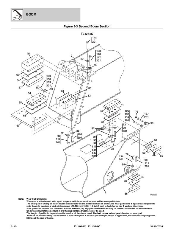
Figure 2-3 Second Boom Section................2282
Figure 2-4 Third Boom Section................2286
Figure 2-5 Fourth Boom Section................2290
Figure 2-6 Extend Chains................2294
Figure 2-7 Retract Chains................2298
Figure 2-8 Manual Quick Coupler................2304
Figure 2-9 Hydraulic Quick Coupler................2306
Section 3 Attachments................2309
Figure 3-1 Standard Carriage................2310
Figure 3-2 Side Tilt Carriage................2312
Figure 3-3 Side Shift Carriage................2316
Figure 3-4 Dual Fork Positioning Carriage................2318
Figure 3-5 100 Degree Swing Carriage................2320
Figure 3-6 180 Degree Swing Carriage................2322
Figure 3-7 Forks & Attaching Parts................2326
Figure 3-8 Fork Mounted Platform................2328
Figure 3-9 Fork Mounted Hook................2330
Figure 3-10 Winch Installation................2332
Figure 3-11 Winch................2334
Figure 3-12 Winch Motor................2338
Figure 3-13 General Purpose Bucket................2340
Figure 3-14 Multi-Purpose Bucket................2342
Figure 3-15 Truss Boom................2344
Figure 3-16 Lifting Hook................2346
Section 4 Engine & Attaching Parts................2349
Figure 4-1 Engine Installation................2350
Figure 4-2 CAT Engine................2352
Figure 4-3 Fuel Tank & Lines................2356
Figure 4-4 Radiator Installation................2360
Figure 4-5 Air Cleaner Installation................2368
Figure 4-6 Exhaust Installation................2370
Section 5 Drive Train................2375
Figure 5-1 Drive Train Components................2376
Figure 5-2 Front Axle................2384
Figure 5-3 Front Axle - Central Housing & Steering................2386
Figure 5-4 Front Axle - Differential................2390
Figure 5-5 Front Axle - Hub Reduction................2394
Figure 5-6 Front Axle - Brakes................2400
Figure 5-7 Front Axle................2404
Figure 5-8 Front Axle - Central Housing................2406
Figure 5-9 Front Axle - Differential................2408
Figure 5-10 Front Axle - Hub Reduction................2410
Figure 5-11 Front Axle - Brakes................2412
Figure 5-12 Front Axle - Steering................2414
Figure 5-13 Front Axle - Trunion................2416
Figure 5-14 Front Axle Differential Assembly................2418
Figure 5-15 Ring Gear Support Kit................2420
Figure 5-16 Planet Gear Carrier Kit................2422
Figure 5-17 Front Axle Support Assembly................2424
Figure 5-18 Rear Axle................2426
Figure 5-19 Rear Axle - Central Housing & Steering................2428
Figure 5-20 Rear Axle - Differential................2432
Figure 5-21 Rear Axle - Hub Reduction................2436
Figure 5-22 Rear Axle - Brakes................2442
Figure 5-23 Rear Axle................2446
Figure 5-24 Rear Axle, Central Housing................2448
Figure 5-25 Rear Axle, Differential................2450
Figure 5-26 Rear Axle, Hub Reduction................2452
Figure 5-27 Rear Axle, Brakes................2454
Figure 5-28 Rear Axle, Steering................2456
Figure 5-29 Rear Axle, Trunion................2458
Figure 5-30 Rear, Differential Assembly................2460
Figure 5-31 Rear Axle, Ring Gear Support Kit................2462
Figure 5-32 Rear Axle, Planet Gear Carrier Kit................2464
Figure 5-33 Rear Axle, Support Assembly................2466
Figure 5-34 Transmission................2468
Figure 5-35 Fender Installation................2470
Figure 5-36 Wheel Assembly................2472
Section 6 Cab................2475
Figure 6-1 Cab Installation................2476
Figure 6-2 Cab Assembly................2482
Figure 6-3 Cab Door................2486
Figure 6-4 Cab Interior................2488
Figure 6-5 Wipers................2490
Figure 6-6 Seats................2492
Figure 6-7 Heater Installation................2494
Figure 6-8 Air Conditioning Installation................2498
Section 7 Controls................2503
Figure 7-1 Brake................2504
Figure 7-2 Accelerator................2506
Figure 7-3 Steering Column................2508
Figure 7-4 Boom Joystick................2510
Figure 7-5 Outrigger & Frame Level/Aux Controllers................2512
Section 8 Hydraulic Circuits................2515
Figure 8-1 Supply Circuit................2516
Figure 8-2 Dump Circuit................2520
Figure 8-3 Steer Select Circuit................2522
Figure 8-4 Service Brake Circuit................2524
Figure 8-5 Boom Joystick Circuit................2526
Figure 8-6 Frame Level/Auxiliary Controller................2528
Figure 8-7 Outrigger Controller................2530
Figure 8-8 Lift Cylinder Circuit................2532
Figure 8-9 Extend/Retract Cylinder Circuit................2534
Figure 8-10 Tilt Cylinder & Compensation Cylinder Circuit................2536
Figure 8-11 Boom Hydraulic Assembly................2538
Figure 8-12 Auxiliary Hydraulic Circuit................2540
Figure 8-13 Frame Level Circuit................2544
Figure 8-14 Outrigger Circuit................2546
Section 9 Hydraulic Components................2549
Figure 9-1 Lift Cylinder & Hardware................2550
Figure 9-2 Extend/Retract Cylinder & Hardware................2554
Figure 9-3 Tilt Cylinder & Hardware................2556
Figure 9-4 Compensation Cylinder & Hardware................2558
Figure 9-5 Frame Level Cylinder & Hardware................2560
Figure 9-6 Outrigger Cylinder & Hardware................2562
Figure 9-7 Stabilizer Cylinder & Hardware................2564
Figure 9-8 Quick Coupler Cylinder................2566
Figure 9-9 Swing Carriage & Side Tilt Carriage Cylinder................2570
Figure 9-10 Side Shift Carriage Cylinder................2574
Figure 9-11 Dual Fork Positioning Carriage Cylinder................2576
Figure 9-12 Main Control Valve................2578
Figure 9-13 Piston Pump................2580
Figure 9-13 Piston Pump................2584
Figure 9-14 Hydraulic Tank................2588
Figure 9-15 Steer Select Valve................2590
Figure 9-16 Brake Valve................2592
Figure 9-17 Hydraulic Manifold Valve................2596
Figure 9-18 Decompression Valve................2598
Figure 9-19 Pressure Reducer Valve................2600
Figure 9-20 Divertor Valve................2602
Section 10 Electrical................2605
Figure 10-1 Engine Compartment Electrical Installation................2606
Figure 10-2 Arctic Kit................2614
Figure 10-3 Boom & Frame Electrical Installation................2616
Figure 10-4 Cab Electrical Installation................2620
Figure 10-5 Cab Switches................2622
Figure 10-6 Work Lights................2624
Figure 10-7 Drive Lights................2630
Figure 10-8 Engine Harness................2632
Figure 10-9 Transmission Harness................2640
Figure 10-10 Frame Harness................2642
Figure 10-11 VEC Options Harness................2650
Figure 10-12 Transmission Relay Harness................2654
Figure 10-13 Enclosed Cab Options Harness................2656
Figure 10-14 Dash Harness................2658
Figure 10-15 Instrument Panel Harness................2660
Figure 10-16 Frame Road Light Harness................2662
Figure 10-17 Boom Work Light Harness................2664
Figure 10-18 Cab Road Light Harness................2666
Figure 10-19 Cab Work Light Harness................2668
Figure 10-20 A/C Harness................2674
Figure 10-21 VEC Harness................2676
Figure 10-22 Product Link Harness................2678
Section 11 Decals................2681
Figure 11-1 Cab & Frame Decals................2682
Figure 11-2 Boom Decals................2686
Maintenance Parts List................2689
Part Number Index................2693


