Hitachi ZX470-6, ZX470LC-6, ZX490H-6, ZX490LCH-6, ZX490R-6, ZX490LCR-6, ZX530LCH-6 Excavator Factory Service & Shop Manual
Catalog:
Model:
Complete workshop repair service manual with electrical wiring diagrams for Hitachi ZX470-6, ZX470LC-6, ZX490H-6, ZX490LCH-6, ZX490R-6, ZX490LCR-6, ZX530LCH-6 Excavators. It's the same service manual used by dealers that guaranteed to be fully functional and intact without any missing page.
Hitachi ZX470-6, ZX470LC-6, ZX490H-6, ZX490LCH-6, ZX490R-6, ZX490LCR-6, ZX530LCH-6 Excavator service & repair manual (including maintenance, overhaul, disassembling & assembling, adjustment, tune-up, operation, inspecting, diagnostic & troubleshooting…) is divided into different sections. Each section covers a specific component or system with detailed illustrations. A table of contents is placed at the beginning of each section. Pages are easily found by category, and each page is expandable for great detail. The printer-ready PDF documents work like a charm on all kinds of devices.
TOJAG50-EN-00 - Hitachi ZX470-6, ZX470LC-6, ZX490H-6, ZX490LCH-6, ZX490R-6, ZX490LCR-6, ZX530LCH-6 Hydraulic Excavator Technical Manual (Operational Principle).pdf
TTJAG50-EN-00 (attach to) - Hitachi ZX470-6, ZX470LC-6, ZX490H-6, ZX490LCH-6, ZX490R-6, ZX490LCR-6, ZX530LCH-6 Hydraulic Excavator Electrical Circuit Diagram.pdf
TTJAG50-EN-00 - Hitachi ZX470-6, ZX470LC-6, ZX490H-6, ZX490LCH-6, ZX490R-6, ZX490LCR-6, ZX530LCH-6 Hydraulic Excavator Technical Manual (Troubleshooting).pdf
WAG50-EN-00 - Hitachi ZX470-6, ZX470LC-6, ZX490H-6, ZX490LCH-6, ZX490R-6, ZX490LCR-6, ZX530LCH-6 Hydraulic Excavator Workshop Manual.pdf
TOTAL PAGES: 1,729
LANGUAGE: ENGLISH
FORMAT: PDF
EXCERPT:
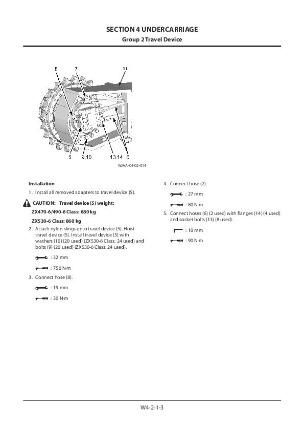
Installation
CAUTION: Lower roller (1) weight:
ZX470-6/490-6 Class: 80 kg
ZX530-6 Class: 110 kg
1. Set lower roller (1) on track link (4) by using a forklift.
2. Lower the machine in order to adjust the lower roller (1) mounting position.
3. Fit the bolt (3) holes of track frame (2) and lower roller (1) and fit the matching marks made when removing. Install lower roller (1) with bolts (3) (4 used).
j 32 mm
m 750 N·m
f NOTE: Install plug (5) with it facing to outside.
...
TOJAG50-EN-00 - Hitachi ZX470-6, ZX470LC-6, ZX490H-6, ZX490LCH-6, ZX490R-6, ZX490LCR-6, ZX530LCH-6 Hydraulic Excavator Technical Manual (Operational Principle)...2
TOJAG50-EN-00...2
CONTENTS...4
INTRODUCTION...10
SYMBOL AND ABBREVIATION...12
SECTION AND GROUP CONTENTS...14
SECTION 1GENERAL...16
Group 1 Specifications...18
Specifications ZX470-6, 470LC-6...18
Working Ranges ZX470-6, 470LC-6...19
Specifications ZX490H-6, 490LCH-6...20
Working Ranges ZX490H-6, 490LCH-6...21
Specifications ZX530LCH-6...22
Working Ranges ZX530LCH-6...23
Group 2 Component Layout...24
Main Component...24
Electrical System (Overview)...26
Electrical System (Rear Tray)...27
Electrical System (Switch Panel)...28
Electrical System (Cab Behind Side)...29
Engine 1...31
Engine 2...32
Aftertreatment Device...33
Pump Device...34
Control Valve...35
DEF Tank...36
Expansion Tank...36
Check Valve...37
Signal Control Valve...37
4-Spool Solenoid Valve Unit...40
2-Spool Solenoid Valve Unit...40
Fan Valve...40
Layout of Attachment Spec. Parts (Hydraulic System)...41
Group 3 Component Specifications...46
Engine...46
Engine Accessories...50
Hydraulic Component...52
Electrical Component...56
SECTION 2SYSTEM...60
Group 1 Controller...62
Outline...62
CAN Circuit...63
Group 2 Control System...66
Outline...66
Engine Control...69
Pump Control...99
Valve Control (Standard)...127
Other Control...159
Group 3 Engine System...172
Outline...172
ECM System...173
Fuel Injection Control...175
Fuel Injection Amount Correction Control...183
EGR Control...185
Preheating Control...187
Variable Turbocharger Control...188
Alarm Control...189
Urea SCR System...190
Engine Output Restriction Control (INDUCEMENT)...201
Aftertreatment Device...205
Aftertreatment Device Regeneration Control...207
Group 4 Hydraulic System...210
Outline...210
Pilot Circuit...211
Main Circuit...227
Breaker/Pulverizer/Crusher Circuit (Optional)...253
Group 5 Electrical System...262
Outline...262
Main Circuit...263
Electric Power Circuit (Key Switch: OFF)...265
CAN Circuit...267
Accessory Circuit (Key Switch: ACC)...269
Starting Circuit (Key Switch: START)...271
Charging Circuit (Key Switch: ON)...273
Surge Voltage Prevention Circuit...277
Pilot Shut-Off Circuit (Key Switch: ON)...279
Auto Shut-Down Circuit/Automatic Engine Stop Circuit at Low Temperature...281
Engine Stop Circuit...283
Monitor Circuit...286
Security Circuit...287
Radio Circuit...289
Air Conditioner Circuit...289
Accessory Circuit...292
Work Light Circuit...293
Wiper/Washer Circuit...295
Cab Light Circuit...297
SECTION 3COMPONENT OPERATION...302
Group 1 Pump Device...304
Outline...304
Main Pump...305
Regulator...307
Pump Control Solenoid Valve...315
Fan Pump...317
Fan Pump Flow Rate Control...319
Pilot Pump...321
Pump Delivery Pressure Sensor...321
Pump Control Pressure Sensor...321
Group 2 Swing Device...322
Outline...322
Swing Reduction Gear...323
Swing Motor...324
Swing Parking Brake...325
Valve Unit...327
Group 3 Control Valve...330
Outline...330
Hydraulic Circuit...347
Flow Combiner Valve...353
Main Relief valve...355
Overload Relief Valve (with Make-Up Function)...359
Boom Overload Relief Valve (Low Pressure)...365
Regenerative Valve...367
Anti-Drift Valve...371
Flow Rate Control Valve...375
Boom Lower Meter-In Cut Valve...383
Bypass Shut-Out Valve...385
Auxiliary Flow Combiner Valve...389
Group 4 Pilot Valve...392
Outline...392
Operation (Front Attachment/Swing and Travel Pilot Valves)...394
Operation (Auxiliary, Counterweight Removal/Installation Pilot Valves)...402
Shockless Function (Only for Travel Pilot Valve)...407
Group 5 Travel Device...408
Outline...408
Travel Reduction Gear...409
Travel Motor...411
Parking Brake...413
Travel Brake Valve...415
Overload Relief Valve...419
Travel Mode Control...421
Group 6 Signal Control Valve...426
Outline...426
Pilot Port...427
Shuttle Valve...431
Shockless Valve...435
Pump 1 and Pump 2 Flow Rate Control Valves...439
Arm Flow Rate Control Valve Control Spool, Flow Combiner Valve Control Spool, Swing Parking Brake Release Spool...441
Group 7 Others (Upperstructure)...442
Pilot Shut-Off Solenoid Valve...442
Solenoid Valve...444
Hose Rupture Valve (Optional)...447
Fan Motor...451
Fan Valve...452
Pilot Relief Valve...458
Shockless Valve...459
Accumulator (Pilot Circuit)...461
Accumulator (Attachment Circuit) (Optional)...462
Selector Valve (Optional)...463
Distribution Valve...465
Group 8 Others (Undercarriage)...468
Swing Bearing...468
Centerjoint...469
Track Adjuster...470
SERVICE MANUAL REVISION REQUEST FORM...474
TTJAG50-EN-00 (attach to) - Hitachi ZX470-6, ZX470LC-6, ZX490H-6, ZX490LCH-6, ZX490R-6, ZX490LCR-6, ZX530LCH-6 Hydraulic Excavator Electrical Circuit Diagram...476
ELECTRICAL CIRCUIT DIAGRAM...476
AIR CONDITIONER CIRCUIT DIAGRAM...477
CONNECTORS...478
CAB HARNESS...479
MAIN HARNESS...480
ENGINE HARNESS...481
PUMP HARNESS...482
CONTROL VALVE HARNESS...483
NOx HARNESS...484
EXPANSION TANK SUB HARNESS...485
DEF SENSOR UNIT HARNESS...486
MONITOR HARNESS...487
KEY SWITCH HARNESS...488
MANUAL REGENERATION SWITCH HARNESS...489
OIL COOLER FAN REVERSE ROTATION SWITCH HARNESS...490
ENGINE STOP SWITCH HARNESS...491
FLOOR EARTH HARNESS...492
PILOT SHUT-OFF SOLENOID VALVE HARNESS...493
STARTER HARNESS...494
GSM (MOBILE COMMUNICATION TERMINAL) HARNESS...495
SATELLITE COMMUNICATION HARNESS...496
AUTO LUBRICATION HARNESS...497
AUTO LUBRICATION ON/OFF SWITCH HARNESS...498
REARVIEW CAMERA HARNESS...499
COUNTERWEIGHT REMOVAL SWITCH HARNESS (OPTION)...500
BOOM MODE SWITCH AND SEAT HEATER SWITCH HARNESS (OPTION)...501
BREAKER HARNESS (OPTION)...502
WORK LIGHT (ON THE CAB ROOF) HARNESS 1 (OPTION)...503
WORK LIGHT (ON THE CAB ROOF) HARNESS 2 (OPTION)...504
ADDITIONAL WORK LIGHT (ON THE CAB ROOF) HARNESS (OPTION)...505
HYDRAULIC CIRCUIT DIAGRAM (STANDARD)...506
HYDRAULIC CIRCUIT DIAGRAM (OPTIONAL)...507
HYDRAULIC CIRCUIT DIAGRAM (WITH HOSE RUPTURE VALVE)(OPTIONAL...508
HYDRAULIC CIRCUIT DIAGRAM (WITH COUNTERWEIGHT REMOVAL AND INSTALLATION DEVICE)(OPTIONAL)...509
TTJAG50-EN-00 - Hitachi ZX470-6, ZX470LC-6, ZX490H-6, ZX490LCH-6, ZX490R-6, ZX490LCR-6, ZX530LCH-6 Hydraulic Excavator Technical Manual (Troubleshooting)...510
TTJAG50-EN-00...510
CONTENTS...512
INTRODUCTION...516
SYMBOL AND ABBREVIATION...518
SAFETY...520
SECTION AND GROUP CONTENTS...562
SECTION 4 OPERATIONAL PERFORMANCE TEST...564
Group 1 Introduction...566
Operational Performance Tests...566
Preparation for Performance Tests...567
Group 2 Standard...568
Operational Performance Standard Table...568
Main Pump P-Q Diagram...572
Fan Pump P-Q Diagram...573
Sensor Activating Range...574
MPDR. Monitor Indicating Values (MC)...575
MPDr. Monitor Indicating Values (ECM)...581
Group 3 Engine Test...582
Engine Speed...582
Lubricant Consumption...585
Group 4 Machine Performance Test...586
Travel Speed...586
Track Revolution Speed...587
Mistrack Check...588
Travel Parking Leakage...589
Swing Speed...590
Swing Function Drift Check...591
Swing Motor Leakage...593
Maximum Swingable Slant Angle...595
Swing Bearing Play...597
Hydraulic Cylinder Cycle Time...599
Dig Function Drift Check...601
Control Lever Operating Force...604
Control Lever Stroke...605
Combined Operation of Boom Raise and Swing Function Check...606
Group 5 Component Test...608
Primary Pilot Pressure...608
Secondary Pilot Pressure...610
4-Spool Solenoid Valve Set Pressure...611
2-Spool Solenoid Valve Set Pressure...612
Main Pump Delivery Pressure...614
Fan Pump Delivery Pressure...615
Main Relief Valve Set Pressure...616
Overload Relief Valve Set Pressure...622
Main Pump Flow Rate Measurement...625
Fan Pump Flow Rate Measurement...631
Swing Motor Drainage...637
Travel Motor Drainage...639
Group 6 Adjustment...642
Pump Learning...642
Torque Adjustment...643
Connection...644
Rewrite of Aftertreatment Device Serial No...646
How to Clear Fault Code...647
Procedure after Replacing DCU and ECM...648
Air Bleeding from the Diesel Exhaust Fluid Defrosting Piping...649
How to Check Manual Regeneration Switch...650
Remedy at DEF Pressure Decrease...651
Remedy at DEF Abnormal Quality...653
Clean DEF Tank...655
Remedy When Mixing Oil DEF Tank...656
SECTION 5 TROUBLESHOOTING...660
Group 1 Diagnosing Procedure...662
Introduction...662
Diagnosis Procedure...663
Electrical System Inspection...666
Precautions for Inspection and Maintenance...667
Instructions for Disconnecting Connectors...669
Fuse Inspection...671
Fusible Link Inspection...674
Battery Voltage Check...675
Alternator Check...676
Continuity Check...677
Voltage and Current Measurement...679
Check by False Signal...686
Test Wire Harness...687
Group 2 Monitor...690
Outline...690
Operating Procedures of Service Menu...691
Setting Menu...660
Inspection of Engine Oil Level, Coolant Level,Hour Meter, and Fuel Gauge...729
Fuel Gauge, Coolant Temperature Gauge,DEF/AdBlue Gauge...730
Group 3 e-Service...732
Outline...732
List of Operation Data...733
Communication System...735
Group 4 Component Layout...736
Main Component...736
Electrical System (Overview)...738
Electrical System (Rear Tray)...739
Electrical System (Switch Panel)...740
Electrical System (Cab Behind Side)...741
Engine 1...743
Engine 2...744
Aftertreatment Device...745
Pump Device...746
Control Valve...747
DEF Tank...748
Expansion Tank...748
Check Valve...749
Signal Control Valve...749
Swing Device...751
Travel Device...751
4-Spool Solenoid Valve Unit...752
Fan Valve...752
2-Spool Solenoid Valve Unit...752
Layout of Attachment Spec. Parts(Hydraulic System)...753
Layout of Control Valve...757
Pilot Port (Signal Control Valve)...773
Layout of Connector...777
Port Layout of Control Valve (Main Circuit)...787
Port Layout of Control Valve (Pilot Circuit)...789
Group 5 Troubleshooting A...792
Troubleshooting A (Base Machine DiagnosisBy Using Fault Codes) Procedure...792
MC Fault Code List...794
ECM Fault Code List...816
DCU Fault Code List...830
Monitor Controller (Monitor) Fault Code List...837
Air Conditioner Controller Fault Code List...841
Communication Terminal Fault Code List...842
MC Fault Codes 11000 to 11002...844
MC Fault Code 11003...845
MC Fault Codes 11004, 11006, 11007,11009Monitor Controller (Monitor)Fault Codes 13002, 13003, 13005...847
CAN0 Harness Check...848
ISO-CAN (Engine) Harness Check...851
MC Fault Codes 11005, 11008, 11010Monitor Controller (Monitor)Fault Codes 13004, 13006, 13007...854
CAN1 Harness Check...855
MC Fault Code 11100...858
MC Fault Code 11101...859
MC Fault Codes 11200, 11202...860
MC Fault Codes 11992, 11994...861
MC Fault Codes 11301 to 11303...862
MC Fault Codes 11304, 11325...863
MC Fault Codes 11995, 11997, 11998...864
MC Fault Codes 11942 to 11944...865
MC Fault Codes 11945, 11978, 11979...866
MC Fault Code 11990...867
MC Fault Code 11405...868
MC Fault Code 11408...869
MC Fault Code 11412...870
MC Fault Code 11428...871
MC Fault Code 11948...872
MC Fault Code 11950...873
MC Fault Code 11951...874
MC Fault Code 11952...875
MC Fault Code 11953...876
MC Fault Code 11981...877
MC Fault Code 11982...878
MC Fault Code 11989...879
MC Fault Code 11802...880
MC Fault Code 11901...881
MC Fault Codes 11910, 11911, 11914,11918, 11920...882
MC Fault Code 11946...883
MC Fault Code 11947...884
MC Fault Codes 11971, 11972...885
MC Fault Codes 11974, 11975...886
MC Fault Codes 11983, 11984...887
MC Fault Codes 11985, 11986...888
MC Fault Codes 20000, 20003, 20005, 20006,20008...889
MC Fault Codes 20009, 20010, 20062...890
Monitor Controller (Information)Fault Codes 13304, 13310...891
Monitor Controller (Information)Fault Code 13311...892
Monitor Controller (Information)Fault Codes 20100 to 20107, 20114...893
Monitor Controller (Information)Fault Codes 20109, 20110, 20113, 20133, 20141,20142, 20145, 20146, 20149...894
Air Conditioner Controller Fault Codes11 to 22...895
Air Conditioner Controller Fault Codes43 to 92...896
Group 6 Troubleshooting B...898
Troubleshooting B (Machine Diagnosis byUsing Trouble Symptom) Procedure...898
Relationship between Machine TroubleSymptoms and Related Parts...900
Correlation between Trouble Symptoms andPart Failures...928
Engine System Troubleshooting...946
All Actuator System Troubleshooting...953
Front Attachment System Troubleshooting...960
Swing System Troubleshooting...973
Travel System Troubleshooting...976
Other System Troubleshooting...980
Exchange Inspection...987
Emergency Boom Lowering Procedure...990
Group 7 Air Conditioner...992
Outline...992
Functions of Main Parts...995
Troubleshooting...1000
Air Conditioner Controller Fault Code List...1001
Air Conditioner Controller Fault Codes 11 to 22...1002
Air Conditioner Controller Fault Codes 43 to 92...1003
Work after Replacing Components...1025
Refill Compressor Oil...1026
Charge Air Conditioner with Refrigerant...1027
Hose and Pipe Tightening Torque...1035
SERVICE MANUAL REVISION REQUEST FORM...1038
The Attached Diagram List...1039
WAG50-EN-00 - Hitachi ZX470-6, ZX470LC-6, ZX490H-6, ZX490LCH-6, ZX490R-6, ZX490LCR-6, ZX530LCH-6 Hydraulic Excavator Workshop Manual...1040
WJAG50-EN-00...1040
CONTENTS...1042
SECTION 1 GENERAL...1042
SECTION 2 ...1044
SECTION 3 ...1046
SECTION 4 ...1048
SECTION 5 ...1050
INTRODUCTION...1052
To The Reader...1052
Additional References...1052
Manual Composition...1052
Page Number...1052
Trademark...1052
Safety Alert Symbol and Headline Notations...1053
Units Used...1053
SYMBOL AND ABBREVIATION...1054
SAFETY...1056
Recognize Safety Information...1056
Understand Signal Words...1056
Follow Safety Instructions...1057
Prepare for Emergencies...1058
Wear Protective Clothing...1058
Protect Against Noise...1059
Inspect Machine...1059
General Precautions for the Cab...1060
Use Handholds and Steps...1061
Adjust the Operator's Seat...1061
Ensure Safety Before Rising from or Leaving Operator’s Seat...1062
Fasten Your Seat Belt...1062
Move and Operate Machine Safely...1063
Operate Only from Operator's Seat...1063
Jump Starting...1064
Keep Riders off Machine...1064
Precautions for Operations...1065
Investigate Job Site Beforehand...1066
Install OPG Guard...1067
Restriction of Attachment Installation...1067
Provide Signals for Jobs Involving Multiple Machines...1068
Confirm Direction of Machine to Be Driven...1068
Drive Machine Safely...1069
Avoid Injury from Rollaway Accidents...1071
Avoid Injury from Back-Over and Swing Accidents...1072
Keep People Clear from Working Area...1073
Never Position the Bucket Over Anyone...1073
Avoid Undercutting...1074
Avoid Tipping...1074
Never Undercut a High Bank...1075
Dig with Caution...1075
Operate with Caution...1075
Avoid Power Lines...1076
Precautions for Lightning...1076
Object Handling...1077
Protect Against Flying Debris...1077
Park Machine Safely...1078
Handle Fluids Safely−Avoid Fires...1078
Transport Safely...1079
Practice Safe Maintenance...1080
Warn Others of Service Work...1081
Support Machine Properly...1081
Stay Clear of Moving Parts...1082
Prevent Parts from Flying...1082
Avoid Injury from Attachment Falling Accident...1083
Prevent Burns...1083
Replace Rubber Hoses Periodically...1084
Avoid High-Pressure Fluids...1084
Prevent Fires...1085
Evacuating in Case of Fire...1087
Beware of Exhaust Fumes...1087
Precautions for Welding and Grinding...1088
Avoid Heating Near Pressurized Fluid Lines...1089
Avoid Applying Heat to Lines Containing Flammable Fluids...1089
Precautions for Handling Accumulator and Gas Damper...1089
Remove Paint Before Welding or Heating...1090
Beware of Asbestos and Silica Dust and Other Contamination...1090
Prevent Battery Explosions...1091
Service Air Conditioning System Safely...1091
Handle Chemical Products Safely...1092
Dispose of Waste Properly...1092
Never Ride Attachment...1093
Notes on Aftertreatment Device...1093
Precautions for Communication Terminal...1093
Precautions for Communication Terminal Equipment...1094
Notes on Protection of Operator’s Station when the Machine Rolls Over...1096
Before Returning the Machine to the Customer...1097
SECTION AND GROUP CONTENTS...1098
SECTION 1 GENERAL...1102
Group 1 Precautions for Disassembling and Assembling...1104
Precautions for Disassembling and Assembling...1104
Group 2 Tightening...1110
Tightening Bolts and Nuts...1110
Piping Joint...1113
Group 3 Painting...1120
Painting...1120
Group 4 Bleeding Air...1122
Bleeding Air from Hydraulic System...1122
Bleeding Air from Fuel System...1123
Air Bleeding from the Diesel Exhaust Fluid Defrosting Piping...1125
Group 5 Preparation...1126
Preparation before Inspection and Maintenance...1126
Hydraulic Circuit Pressure Release Procedure...1128
Pressure Release from Hydraulic Oil Tank...1129
Pressure Release from Expansion Tank...1130
SECTION 2 MAINTENANCE STANDARD...1134
Group 1 Upperstructure...1136
Pump Device...1136
Swing Motor...1140
Group 2 Undercarriage...1144
Travel Motor...1144
Sprocket...1146
Center Joint...1148
Front Idler...1150
Upper Roller...1152
Lower Roller...1153
Track...1154
Group 3 Front Attachment...1158
Pin and Bushing...1158
Side Cutter...1160
Point (4512365)...1161
Standard Dimensions for Arm and Bucket Connection...1162
Standard Dimensions for Arm and Boom Connection...1163
Cylinder...1164
SECTION 3 UPPERSTRUCTURE...1168
Group 1 Cab...1170
Removal and Installation of Cab...1170
Dimensions of Cab Glass (Standard Cab)...1198
Dimensions of Cab Glass (H Cab)...1217
Group 2 Counterweight...1220
Removal and Installation of Counterweight...1220
Group 3 Main Frame...1226
Removal and Installation of Main Frame...1226
Group 4 Engine...1236
Removal and Installation of Engine...1236
Group 8 Pump Device...1268
Removal and Installation of Pump Device...1268
Disassembly of Main Pump...1288
Assembly of Main Pump...1293
Disassembly of Regulator for Main Pump...1300
Assembly of Regulator for Main Pump...1302
Disassembly of Fan Pump...1306
Assembly of Fan Pump...1310
Structure of Pilot Pump...1314
Group 9 Control Valve...1316
Removal and Installation of Control Valve...1316
Disassembly and Assembly of Housing...1330
Disassembly of Control Valve 4-Spool Side...1334
Assembly of Control Valve 4-Spool Side...1342
Disassembly of Control Valve 5-Spool Side...1350
Assembly of Control Valve 5-Spool Side...1357
Group 10 Swing Device...1364
Removal and Installation of Swing Device...1364
Disassembly of Swing Device...1368
Assembly of Swing Device...1374
Disassembly of Swing Motor...1380
Assembly of Swing Motor...1383
Group 11 Pilot Valve...1388
Removal and Installation of Pilot Valve (Left)...1388
Removal and Installation of Pilot Valve (Right)...1400
Removal and Installation of Travel Pilot Valve...1416
Disassembly of Pilot Valves (Right and Left)...1420
Assembly of Pilot Valves (Right and Left)...1423
Disassembly of Travel Pilot Valve...1426
Assembly of Travel Pilot Valve...1430
Group 12 Solenoid Valve...1436
Removal and Installation of Pilot Shut-Off Solenoid Valve...1436
Removal and Installation of 4-Spool Solenoid Valve Unit...1440
Removal and Installation of 2-Spool Solenoid Valve Unit...1444
Removal and Installation of Fan Pump Control Solenoid Valve...1448
Disassembly of Pilot Shut-Off Solenoid Valve...1452
Assembly of Pilot Shut-Off Solenoid Valve...1454
Structure of 4-Spool Solenoid Valve Unit...1456
Structure of 2-Spool Solenoid Valve Unit...1458
Structure of Fan Pump Control Solenoid Valve...1460
Group 13 Signal Control Valve...1462
Removal and Installation of Signal Control Valve...1462
Structure of Signal Control Valve...1468
Group 14 Aftertreatment Device...1472
Removal and Installation of Aftertreatment Device...1472
Group 15 DEF Tank...1480
Removal and Installation of DEF Tank...1480
Group 16 Coolant Control Valve...1496
Removal and Installation of Coolant Control Valve...1496
Group 17 DEF Supply Module...1502
Removal and Installation of DEF Supply Module...1502
Group 19 Fan Valve...1506
Removal and Installation of Fan Valve...1506
Structure of Fan Valve...1540
Group 20 Fan Motor...1542
Removal and Installation of Fan Motor...1542
Structure of Fan Motor...1550
Group 21 Shockless Valve...1552
Removal and Installation of Shockless Valve...1552
Structure of Shockless Valve...1554
SECTION 4 UNDERCARRIAGE...1558
Group 1 Swing Bearing...1560
Removal and Installation of Swing Bearing...1560
Disassembly of Swing Bearing...1564
Assembly of Swing Bearing...1567
Group 2 Travel Device...1570
Removal and Installation of Travel Device...1570
Disassembly of Travel Device...1574
Assembly of Travel Device...1581
Disassembly of Travel Motor...1590
Assembly of Travel Motor...1594
Disassembly of Brake Valve...1600
Assembly of Brake Valve...1603
Group 3 Center Joint...1608
Removal and Installation of Center Joint...1608
Disassembly of Center Joint...1612
Assembly of Center Joint...1614
Replacement of Body and Spindle...1617
Group 4 Track Adjuster...1618
Removal and Installation of Track Adjuster...1618
Disassembly of Track Adjuster...1620
Assembly of Track Adjuster...1625
Group 5 Front Idler...1630
Removal and Installation of Front Idler...1630
Disassembly of Front Idler...1632
Assembly of Front Idler...1635
Group 6 Upper and Lower Rollers...1640
Removal and Installation of Upper Roller...1640
Removal and Installation of Lower Roller...1644
Disassembly of Lower Roller...1650
Assembly of Lower Roller...1652
Group 7 Track...1656
Removal and Installation of Track...1656
SECTION 5 FRONT ATTACHMENT...1672
Group 1 Front Attachment...1674
Removal and Installation of Front Attachment...1674
Removal and Installation of Bushing...1680
Group 2 Cylinder...1682
Removal and Installation of Boom Cylinder...1682
Removal and Installation of Arm Cylinder...1690
Removal and Installation of Bucket Cylinder...1698
Disassembly of Boom, Arm, and Bucket Cylinders...1702
Assembly of Boom, Arm, and Bucket Cylinders...1708
Group 3 Hose Rupture Valve...1714
Removal and Installation of Hose Rupture Valve for Boom Cylinder...1714
Removal and Installation of Hose Rupture Valve for Arm Cylinder...1718
Structure of Hose Rupture Valve for Boom Cylinder...1722
Structure of Hose Rupture Valve for Arm Cylinder (Bottom Side)...1724
Structure of Hose Rupture Valve for Arm Cylinder (Rod Side)...1726
SERVICE MANUAL REVISION REQUEST FORM...1730


