John Deere 450J, 550J, 650J Crawler Dozer Repair Technical Manual (TM10294)
Catalog:
Model:
Complete technical Operation & Test Manual with electrical wiring diagrams for John Deere 450J, 550J, 650J Crawler Dozer. It's the same service manual used by dealers that guaranteed to be fully functional and intact without any missing page.
John Deere 450J, 550J, 650J Crawler Dozer Operation & Test Technical Manual (including maintenance, overhaul, disassembling & assembling, adjustment, tune-up, operation, inspecting, diagnostic & troubleshooting…) is divided into different sections. Each section covers a specific component or system with detailed illustrations. A table of contents is placed at the beginning of each section. Pages are easily found by category, and each page is expandable for great detail. The printer-ready PDF documents work like a charm on all kinds of devices.
TM10294 - 450J, 550J, 650J Crawler Dozer(S.N. 141667—159986) Operation & Test Technical Manual.pdf
MAIN SECTIONS
00 - General Information
01 - Tracks
02 - Axles and Suspension Systems
03 - Transmission
04 - Engine
05 - Engine Auxiliary Systems
07 - Dampener Drive
11 - Park Brake
15 - Equipement Attaching
18 - Operator's Station
19 - Sheet Metal and Styling
21 - Main Hydraulic System
32 - Bulldozer
..
TABLE OF CONTENTS....1
Section 00: General Information....11
Group 01: Safety....11
Recognize Safety Information....14
Follow Safety Instructions....15
Operate Only If Qualified....16
Wear Protective Equipment....17
Avoid Unauthorized Machine Modifications....18
Inspect Machine....19
Stay Clear of Moving Parts....20
Avoid High-Pressure Fluids....21
Avoid High-Pressure Oil....22
Beware of Exhaust Fumes....23
Prevent Fires....24
Prevent Battery Explosions....25
Handle Chemical Products Safely....26
Dispose of Waste Properly....27
Prepare for Emergencies....28
Add Cab Guarding For Special Uses....29
Start Only From Operator's Seat....30
Prevent Unintended Machine Movement....31
Avoid Work Site Hazards....32
Keep Riders Off Machine....34
Avoid Backover Accidents....35
Avoid Machine Tip Over....36
Park And Prepare For Service Safely....38
Service Cooling System Safely....39
Remove Paint Before Welding or Heating....40
Make Welding Repairs Safely....41
Drive Metal Pins Safely....42
Group 03: Torque Values....11
Metric Bolt and Cap Screw Torque Values....45
Additional Metric Cap Screw Torque Values....47
Unified Inch Bolt and Cap Screw Torque Values....49
Service Recommendations for 37° Flare and 30° Cone Seat Connectors....51
Service Recommendations for O-Ring Boss Fittings....53
O-Ring Boss Fittings In Aluminum Housing Service Recommendations—Excavators....55
Service Recommendations for Flared Connections—Straight or Tapered Threads....58
Service Recommendations For Flat Face O-Ring Seal Fittings....60
O-Ring Face Seal Fittings With SAE Inch Hex Nut And Stud End For High Pressure Service Recommendations....62
O-Ring Face Seal Fittings With Metric Hex Nut And Stud End For Standard Pressure Service Recommendations....64
O-Ring Face Seal Fittings With Metric Hex Nut And Stud End For High Pressure Service Recommendations....67
Service Recommendations for Metric Series Four Bolt Flange Fitting....70
Service Recommendations For Inch Series Four Bolt Flange Fittings....72
Inch Series Four Bolt Flange Fitting For High Pressure Service Recommendations....74
Service Recommendations For Non-Restricted Banjo (Adjustable) Fittings....76
Service Recommendations For O-Ring Boss Fittings With Shoulder....79
Metric 24° O-Ring Seal DIN 20078 Service Recommendations....82
Section 01: Tracks....86
Group 0130: Track System....86
Rock Guards and Chain Guides Remove and Install....89
Carrier Roller Remove and Install....91
Carrier Roller Disassemble and Assemble....95
Metal Face Seals Inspection....98
Track Roller Remove and Install....100
Track Roller Disassemble and Assemble....102
Track Roller Leakage Test....104
Track Shoe Remove and Install....105
Sealed Track Chain Removal....108
Sealed Track Chain Disassemble and Assemble....113
Sealed Track Chain Installation....114
Lubricated Track Chain (Saw Tooth Master Split Link) Remove and Install....117
Lubricated Track Chain Disassembly (Turn Bushings and Lubricate Chain)....122
Lubricated Track Chain Assembly (Turn Bushings and Lubricate Chain)....126
Lubricated Track Chain Disassemble and Assemble (Turn Pins and Not Lubricate)....135
Front Idler Remove and Install....142
Front Idler Disassemble, Inspect, and Assemble....144
Front Idler Adjustment....147
Front Idler Oil Level Check....149
Track Tension Adjuster Remove and Disassemble....151
Track Tension Adjuster Assemble and Install....153
Track Idler Recoil Spring Remove and Install....155
Track Idler Recoil Spring Disassemble and Assemble....157
Sprocket Remove and Install....163
Track Frame Remove and Install....165
Track Frame Disassemble and Assemble....167
Frame Wear Strips Remove and Install....170
Section 02: Axles and Suspension Systems....172
Group 0201: Drive Axle Housing and Support....172
Final Drive Remove and Install....178
Group 0250: Axle Shaft, Bearings, and Reduction Gear....172
Final Drive Disassemble and Assemble....199
Section 03: Transmission....215
Group 0300: Removal and Installation....215
Hydrostatic Pump Remove and Install....228
Hydrostatic Motor Remove and Install....240
Group 0315: Controls Linkage....215
Transmission Control Lever (TCL) Remove and Install....245
Transmission Control Lever (TCL) Disassemble and Assemble (S.N. —130885)....247
Transmission Control Lever (TCL) with Integrated Grade Control (IGC) Disassemble and Assemble (S.N. 130886—)....271
Group 0360: Hydrostatic System....215
Hydrostatic Pumps Disassemble....286
Hydrostatic Charge Pump Disassemble and Assemble....299
Pump Displacement Control Valve (PDCV) Disassemble and Assemble....305
Multi-Function Valve Disassemble and Assemble....309
Neutral Charge Relief Valve Disassemble and Assemble....312
Hydrostatic Pump Assemble....313
Hydrostatic Motor Disassemble....326
Hydrostatic Motor Assemble....332
Oil Cooler Thermal Bypass Valve Remove and Install....349
Hydrostatic Filter Remove and Install....351
Hydrostatic Filter Disassemble and Assemble....352
Hydrostatic Reservoir Remove and Install....354
Section 04: Engine....358
Group 0400: Removal and Installation....358
Engine Remove and Install....367
Section 05: Engine Auxiliary Systems....375
Group 0505: Cold Weather Starting Aids....375
Engine Coolant Heater Remove and Install....379
Start Aid Remove and Install....382
Starting Aid Solenoid Remove and Install....384
Group 0510: Radiator and Fan Shroud....375
Fan Blade and Shroud Remove and Install (450J, 550J)....387
Fan Blade and Shroud Remove and Install (650J)....389
Cooling Package Remove and Install (450J, 550J)....392
Cooling Package Remove and Install (650J)....395
Sand Shield Remove and Install....400
Group 0515: Engine Speed Control....375
Decelerator/Brake Pedal Remove and Install....402
Decelerator/Brake Pedal Disassemble and Assemble....403
Group 0520: Intake System....375
Air Cleaner Remove and Install 550J and 650J....412
Group 0530: External Exhaust System....375
Muffler Without Turbocharger Remove and Install....415
Muffler With Turbocharger Remove and Install....416
Group 0540: Mounting Frame....375
Engine and Power Train Mounting....419
Group 0560: External Fuel Supply System....375
Fuel Tank Remove and Install....423
Section 07: Dampener Drive....425
Group 0752: Elements....425
Dampener Drive Remove and Install....428
Section 11: Park Brake....430
Group 1100: Removal and Installation....430
Park Brake Valve Remove and Install....432
Park Brake Remove and Install....433
Group 1115: Control Linkage....430
Park Lock Linkage Remove and Install....439
Park Lock Linkage Disassemble and Assemble....441
Group 1160: Hydraulic System....430
Park Brake Valve Disassemble and Assemble....448
Park Brake Disassemble and Assemble....451
Section 15: Equipment Attaching....456
Group 1540: Ripper....456
Ripper Remove and Install....461
Section 18: Operator's Station....465
Group 1800: Removal and Installation....465
Cab or ROPS Remove and Install....477
Group 1810: Operator's Enclosure....465
Slide Glass Remove and Install....489
Stationary Glass Remove and Install....491
Sliding Window Remove and Install....493
Front Window Wiper Remove and Install....495
Door Window Wipers Remove and Install....497
Rear Window Wiper Remove and Install....499
Window Washer Pumps Remove and Install....501
Group 1821: Seat and Seat Belt....465
Standard Seat Remove and Install (Old)....506
Deluxe Seat Remove and Install....510
Air Suspension Seat Remove and Install....519
Group 1830: Heating and Air Conditioning....465
R134a Refrigerant Cautions....523
R134a Compressor Oil Charge Check....524
R134a Compressor Oil Removal....525
R134a Component Oil Charge....526
Leakage Testing....528
R134a Refrigerant Recovery, Recycling and Charging Station Installation Procedure....529
Recover R134a System....531
Evacuate R134a System....533
Charge R134a System....535
Air Conditioner System Cleaning Procedures....537
Purge R134a System....538
Flush R134a System....539
Evaporator or Heater Core Remove and Install....542
Expansion Valve Remove and Install....546
A/C Freeze Switch Remove and Install....547
Upper Cab Heater Blower Motor and Heater Blower Resistor Remove and Install....548
Cab Upper Heater Disassemble and Assemble....549
Cab or ROPS Under Seat Heater Disassemble and Assemble....551
Receiver-Dryer Remove and Install....554
Condenser Remove and Install....555
Compressor Remove and Install....556
Compressor Clutch Disassemble and Assemble....558
Clutch Hub Clearance Check....560
Compressor Manifold Inspect....561
Compressor Disassemble and Assemble....562
Section 19: Sheet Metal and Styling....566
Group 1910: Hood and Engine Enclosure....566
Hood Remove and Install....569
Hood Support and Engine Side Shields Remove and Install....571
Group 1921: Grille and Grille Housing....566
Grille and Grille Housing Removal....575
Grille and Grille Housing Installation....578
Section 21: Main Hydraulic System....582
Group 2160: Hydraulic System....582
Hydraulic Pump Remove and Install....587
Hydraulic Pump (With Winch Option) Disassemble and Assemble....591
Hydraulic Pump (Without Winch Option) Disassemble and Assemble....596
Hydraulic Reservoir Remove and Install....599
Hydraulic Reservoir and Hydrostatic Reservoir Cleanout Cover Remove and Install....603
Hydraulic Reservoir Disassemble and Assemble....607
Hydraulic Filter Remove and Install....609
Hydraulic Filter Disassemble and Assemble....610
Section 32: Bulldozer....612
Group 3201: Blades....612
Blade Remove and Install....617
Blade Retainer Split Bearing Installation....621
Cutting Edges and End Bits Remove and Install....623
Group 3215: Control Linkage....612
Hydraulic Control Lever Linkage Remove and Install....627
Auxiliary Hydraulic Control Lever Linkage Remove and Install....630
Group 3240: Frames....612
C-Frame Remove and Install....636
C-Frame Remove and Install (New)....640
Group 3260: Hydraulic System....612
Hydraulic Control Valve Remove and Install....651
Hydraulic Control Valve Disassemble and Assemble....654
Hydraulic Control Valve Disassemble and Assemble—IGC....656
Wiper Seals and Lip Seals on Hydraulic Control Valve Remove and Install....659
Auxiliary Control Valve Section Disassemble and Assemble....667
Angle Control Valve Section Disassemble and Assemble....669
Tilt Control Valve Section Disassemble and Assemble....671
Lift Control Valve Section Disassemble and Assemble....673
System and Angle Circuit Relief Valve Disassemble and Assemble....676
Integrated Grade Control (IGC) Lever Remove and Install (S.N. 130886—)....678
Integrated Grade Control (IGC) Lever Disassemble and Assemble (S.N. 130886—)....681
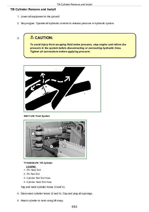
Tilt Cylinder Remove and Install....683
Angle Cylinder Remove and Install....685
Lift Cylinder Remove and Install....687
Angle, Lift, and Tilt Cylinders Disassemble and Assemble (John Deere 120 Series Cylinders)....689
Section 9900: Dealer Fabricated Tools....690
Group 0999: Dealer Fabricated Tools....690
DF1041 Track Nut Removal Tool....692
DF1063 Final Drive Lift Bracket....693
DFT1087 Track Recoil Spring Disassembly and Assembly Guard Tool....695
DFT1119 Pump Support....696
DFT1130 Adapter....697
DFT1132 Hydrostatic Motor Removal and Installation Tool....698
DFT1137 Hydrostatic Motor Removal and Installation Tool....699
DFT1165 Left Hand Hydrostatic Motor Lifting Bracket....700
DFT1166 Final Drive Lifting Bracket Adapter....701
DFT1167 Final Drive Lifting Bracket Adapter Spacer....702
DFT1168 Right Hand Hydrostatic Motor Lifting Bracket....703
DFT1211 Final Drive Lifting Bracket Adapter....704
DFRW20 Compressor Holding Fixture....705
ST4920 Track Recoil Spring Disassembly and Assembly Tool....706
John Deere 450J, 550J, 650J Crawler Dozers Diagnostics Technical Manual (TM10294)


