Bobcat Loaders 763, 763 High Flow, 773, 773 High Flow, 773 Turbo (G Series) Repair Service Manual + Operation & Maintenance Manual
Catalog:
Model:
Complete repair service manuals with electrical wiring diagrams for Bobcat Loaders 763, 763 High Flow, 773, 773 High Flow, 773 Turbo (G Series), with technical information to maintain, diagnose, repair, and service like professional mechanics.
Bobcat Loaders 763, 763 High Flow, 773, 773 High Flow, 773 Turbo (G Series) workshop service repair manual includes:
* Numbered table of contents easy to use so that you can find the information you need fast.
* Detailed sub-steps expand on repair procedure information
* Numbered instructions guide you through every repair procedure step by step.
* Troubleshooting and electrical service procedures are combined with detailed wiring diagrams for ease of use.
* Notes, cautions and warnings throughout each chapter pinpoint critical information.
* Bold figure number help you quickly match illustrations with instructions.
* Detailed illustrations, drawings and photos guide you through every procedure.
* Enlarged inset helps you identify and examine parts in detail.
MAIN SECTIONS
CONTENTS
FOREWORD
SAFETY INSTRUCTIONS
SERIAL NUMBER LOCATION
DELIVERY REPORT
BOBCAT LOADER IDENTIFICATION
SAFETY AND MAINTENANCE
HYDRAULIC SYSTEM
HYDROSTATIC SYSTEM
DRIVE SYSTEM
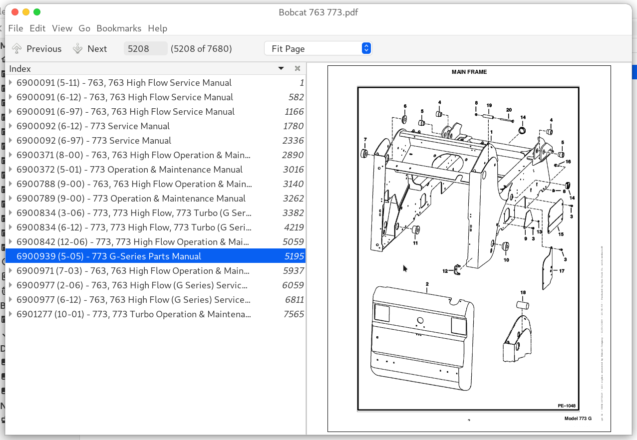
MAIN FRAME
ELECTRICAL SYSTEM & ANALYSIS
ENGINE SERVICE
HEATER
SPECIFICATIONS
Total Pages: 7,680 pages
File Format: PDF (bookmarked, Searchable, Printable, high quality)
Language: English
6900091 (5-11) - 763, 763 High Flow Service Manual.pdf
6900091 (6-12) - 763, 763 High Flow Service Manual.pdf
6900091 (6-97) - 763, 763 High Flow Service Manual.pdf
6900092 (6-12) - 773 Service Manual.pdf
6900092 (6-97) - 773 Service Manual.pdf
6900371 (8-00) - 763, 763 High Flow Operation & Maintenance Manual.pdf
6900372 (5-01) - 773 Operation & Maintenance Manual.pdf
6900788 (9-00) - 763, 763 High Flow Operation & Maintenance Manual.pdf
6900789 (9-00) - 773 Operation & Maintenance Manual.pdf
6900834 (3-06) - 773, 773 High Flow, 773 Turbo (G Series) Service Manual.pdf
6900834 (6-12) - 773, 773 High Flow, 773 Turbo (G Series) Service Manual.pdf
6900842 (12-06) - 773, 773 High Flow Operation & Maintenance Manual.pdf
6900939 (5-05) - 773 G-Series Parts Manual.pdf
6900971 (7-03) - 763, 763 High Flow Operation & Maintenance Manual.pdf
6900977 (2-06) - 763, 763 High Flow (G Series) Service Manual.pdf
6900977 (6-12) - 763, 763 High Flow (G Series) Service Manual.pdf
6901277 (10-01) - 773, 773 Turbo Operation & Maintenance Manual.pdf
TABLE OF CONTENTS
6900091 (5-11) - 763, 763 High Flow Service Manual................1
MAINTENANCE SAFETY................3
ALPHABETICAL INDEX................5
CONTENTS................7
FOREWORD................9
SAFETY INSTRUCTIONS................11
FIRE PREVENTION................12
SERIAL NUMBER LOCATIONS................13
LOADER SERIAL NUMBER................13
ENGINE SERIAL NUMBER................13
DELIVERY REPORT................13
BOBCAT LOADER IDENTIFICATION................14
PREVENTIVE MAINTENANCE................15
SERVICE SCHEDULE................17
LIFTING AND BLOCKING THE LOADER................18
Procedure................18
TRANSPORTING THE BOBCAT LOADER................19
TOWING THE LOADER................19
STOPPING THE BOBCAT LOADER................19
LIFTING THE LOADER................20
Single Point Lift................20
LIFT ARM SUPPORT DEVICE................21
Engaging The Lift Arm Support Device................21
Disengaging The Lift Arm Support Device................22
OPERATOR CAB................23
Description................23
Emergency Exit................23
Raising The Operator Cab................24
Lowering The Operator Cab................25
SEAT BAR RESTRAINT SYSTEM (Foot Pedals)................26
Description................26
Seat Bar Inspection................26
Seat Bar Maintenance................26
SEAT BAR RESTRAINT SYSTEM (Mechanical Hand Controls)................27
Description................27
Seat Bar Inspection................27
Seat Bar Maintenance................27
SEAT BAR RESTRAINT SYSTEM (Advanced Hand Controls)................28
Description................28
Seat Bar Inspection................28
Seat Bar Maintenance................28
AIR CLEANER SERVICE................29
Replacing Filter Element................29
FUEL SYSTEM................31
Fuel Specifications................31
Filling The Fuel Tank................31
Fuel Filter................31
Removing Air From The Fuel System................32
ENGINE LUBRICATION SYSTEM................33
Checking Engine Oil................33
Oil Chart................33
Replacing Oil And Filter................33
ENGINE COOLING SYSTEM................35
Cleaning The Cooling System................35
Checking The Coolant Level................35
Replacing The Coolant................36
ALTERNATOR BELT................37
Adjusting The Alternator Belt................37
FAN GEARBOX................37
Checking And Maintaining................37
HYDRAULIC/HYDROSTATIC SYSTEM................38
Checking And Adding Fluid................38
Replacing Hydraulic/Hydrostatic Filter................38
Replacing Hydraulic Fluid................39
Hydraulic Reservoir Breather Cap................40
SPARK ARRESTOR MUFFLER................41
Cleaning Procedure................41
TIRE MAINTENANCE................42
Wheel Nuts................42
Tire Rotation................42
Tire Mounting................42
FINAL DRIVE TRANSMISSION (CHAINCASE)................43
Checking And Adding Oil................43
Replacing Oil In The Chaincase................43
DRIVE BELT................44
Adjusting The Drive Belt Equipped With The Spring Loaded Drive Idler................44
Adjusting The Drive Belt Equipped With The Fixed Drive Idler................46
Drive Belt Replacement................47
LUBRICATION OF THE BOBCAT LOADER................48
Procedure................48
BOB–TACH................50
Inspection And Maintenance................50
REMOTE START SWITCH................51
Procedure................51
HYDRAULIC SYSTEM................53
HYDRAULIC/HYDROSTATIC SCHEMATICS................57
TROUBLESHOOTING................85
HYDRAULIC SYSTEM INFORMATION................86
Tightening Procedure................86
LIFT CYLINDER(S)................87
Checking The Lift Cylinder(s) For Internal Leakage................87
Removal And Installation................87
TILT CYLINDER................88
Checking The Tilt Cylinder For Internal Leakage................88
Removal And Installation................88
Rod End Seal Replacement................89
HYDRAULIC CYLINDER IDENTIFICATION................90
Lift Cylinder Components................90
Tilt Cylinder Components................91
HYDRAULIC CYLINDERS................92
Disassembly................92
Assembly................94
BICS™ VALVE (S/N 512220298 & Above, 512440721 & Above and 512612258 & Above)................100
Removal................100
Lift Arm By–Pass Orifice Disassembly................101
Check Valve Disassembly................101
Lock Valve Disassembly................102
BICS™ Valve Solenoid Disassembly................103
BICS™ Valve Solenoid Assembly................104
Lock Valve Assembly................105
Check Valve Assembly................105
Lift Arm By–Pass Orifice Assembly................106
Installation................107
CONTROL VALVE (S/N 512220298 & Above, 512440721 & Above and 512612258 & Above)................108
Removal And Installation................108
Identification Chart................111
Disassembly................112
Lift Base End Restrictor Disassembly................112
Load Check Valve Disassembly................112
Main Relief Valve Disassembly................113
Port Relief Valve Disassembly................114
Anti–Cavitation Valve Disassembly................115
Rubber Boot Disassembly................116
Lift Spool And Detent Disassembly................117
Tilt Spool And Centering Spring Disassembly................120
Auxiliary Spool Disassembly................122
Auxiliary Electric Solenoid Disassembly................123
Port–Auxiliary Section Disassembly................124
Cleaning And Inspection................124
Port–Auxiliary Section Assembly................125
Auxiliary Electric Solenoid Assembly................125
Auxiliary Spool Assembly................126
Tilt Spool And Centering Spring Assembly................127
Lift Spool And Detent Assembly................129
Rubber Boot Assembly................131
Anti–Cavitation Valve Assembly................132
Port Relief Valve Assembly................133
Main Relief Valve Assembly................134
Load Check Valve Assembly................134
Spool Seal Installation................136
CONTROL VALVE (S/N 512220297 & Below,512440720 & Below and 512612257 & Below)................137
Removal And Installation................137
Identification Chart................140
Disassembly And Assembly................141
Load Check Valve................141
Main Relief Valve................142
Port Relief Valve................142
Anti–Cavitation Valve................143
Rubber Boot................144
Lift Spool Detent................145
Tilt Centering Spring................149
Auxiliary Spool................150
Auxiliary Electric Solenoid................151
Plug/Port Relief Valve................152
Inspection................152
Identification And Installation Of Spool Seal................153
MAIN RELIEF VALVE................154
Checking................154
Adjustment................155
Removal And Installation................155
HYDRAULIC PUMP................156
Removal And Installation................156
Checking The Output Of The Hydraulic Pump................158
Checking The Output Of The High Flow Hydraulic Pump (763H)................160
Disassembly And Assembly................161
Inspection................163
Identification................163
Removal And Installation (763H)................164
Identification (763H)................167
Disassembly And Assembly (763H)................168
HYDRAULIC FILTER HOUSING................171
Removal And Installation................171
HYDRAULIC FLUID RESERVOIR................172
Removal And Installation................172
CONTROL PEDALS................173
Removal And Installation................173
Pedal Adjustment................173
SELECT VALVE (763H)................174
Checking the Main Relief Valve in High Horsepower Select Valve................174
Removal And Installation................175
Disassembly And Assembly (New Style Valve)................177
Solenoid Testing (New Style Valve)................178
Disassembly And Assembly (Old Style Valve)................179
Solenoid Testing (Old Style Valve)................180
PEDAL INTERLOCK LINKAGE................181
Removal And Installation................181
Adjustment................182
LIFT LOCK BY–PASS VALVE................183
Removal And Installation (S/N 512220298 & Above, S/N 512440721 & Above, S/N 512612258 & Above)................183
Removal And Installation (S/N 512220297 & Below, S/N 512440720 & Below, S/N 512612257 & Below)................185
Disassembly And Assembly (S/N 512220297 & Below, S/N 512440720 & Below, S/N 512612257 & Below)................186
TILT LOCK VALVE................187
Removal And Installation (S/N 512220297 & Below, S/N 512440720 & Below, S/N 512612257 & Below)................187
Disassembly And Assembly (S/N 512220297 & Below, S/N 512440720 & Below, S/N 512612257 & Below)................189
HYDROSTATIC SYSTEM................191
TROUBLESHOOTING................193
HYDROSTATIC SYSTEM INFORMATION................194
Replenishing Valve Function................194
Checking Charge Pressure................194
CONTROL PANEL................195
Removal And Installation................195
Steering Shock Removal And Installation................196
Steering Shaft Removal And Installation................196
Steering Shaft Disassembly And Assembly................196
Steering Lever Removal And Installation................197
Rubber Boot Replacement................197
STEERING LINKAGE................198
Removal And Installation................198
Steering Linkage Adjustment................200
Steering Neutral Adjustment................202
HYDROSTATIC DRIVE MOTOR................204
Removal And Installation................204
Identification (S/N 512218843 & Below, S/N 512612191 & Below & S/N 512440645 & Below)................205
Disassembly And Assembly (S/N 512218843 & Below, S/N 512612191 & Below & S/N 512440645 & Below)................206
nspection (S/N 512218843 & Below, S/N 512612191 & Below & S/N 512440645 & Below)................211
Timing The Hydrostatic Motor (S/N 512218843 & Below, S/N 512612191 & Below & S/N 512440645 & Below)................212
HYDROSTATIC MOTOR 30 SERIES................213
Identification (S/N 512218844 & Above, S/N 512612192 & Above, & S/N 512440646 & Above)................213
Disassembly (S/N 512218844 & Above, S/N 512612192 & Above, & S/N 512440646 & Above)................214
Assembly (S/N 512218844 & Above, S/N 512612192 & Above, & S/N 512440646 & Above)................219
HYDROSTATIC PUMP................225
Removal And Installation................225
Identification MODEL: 763................228
Disassembly And Assembly................230
Inspection................238
Swashplate Pre–Load................240
DRIVE BELT HOUSING................241
Removal And Installation................241
SPRING LOADED DRIVE BELT TENSIONER PULLEY................243
Removal And Installation................243
Identification................244
Disassembly................245
Assembly................246
FIXED DRIVE BELT TENSIONER PULLEY................248
Removal And Installation................248
Identification................249
Disassembly................250
Assembly................252
Checking Pulley End Play................256
OIL COOLER................256
Removal And Installation................256
DRIVE SYSTEM................257
PARKING BRAKE................259
Removal And Installation................259
Disassembly And Assembly................259
PARKING BRAKE DISC................260
Removal And Installation................260
TRACTION LOCK GUIDES................261
Disassembly................261
Assembly................262
CHAINCASE FLUID................264
Removing Oil From The Chaincase................264
CHAINCASE COVERS................265
Center Chaincase Cover Removal And Installation................265
Front Chaincase Cover Removal And Installation................266
Rear Chaincase Cover Removal And Installation................266
MOTOR CARRIER................267
Shaft Seal Replacement................267
Removal And Installation................269
Disassembly................270
Assembly................271
AXLE SEAL................275
Removal And Installation................275
AXLE, SPROCKET AND BEARINGS................277
Removal And Installation................277
DRIVE CHAIN................281
Removal................281
MAIN FRAME................283
SEAT BAR (W/GAS CYLINDER)................285
Removal And Installation................285
Assembly................287
Compressing the Gas Cylinder................288
SEAT BAR (W/COMPRESSION SPRING)................289
Removal And Installation................289
Assembling Components................292
Compression Spring Disassembly And Assembly................292
OPERATOR CAB GAS CYLINDER................293
Removal And Installation................293
Disassembly And Assembly................293
OPERATOR CAB................294
Removal And Installation................294
OPERATOR SEAT................297
Removal And Installation................297
BOB–TACH................298
Removal And Installation................298
Bob–Tach Lever And Wedge................300
Bob–Tach Stops................301
LIFT ARMS................302
Removal And Installation................302
REAR GRILL................306
Removal And Installation................306
FUEL TANK................307
Removal And Installation................307
Fuel Level Sender................308
REAR DOOR................309
Removal And Installation (2 piece door)................309
Removal And Installation (One Piece Door)................310
Hood Removal And Installation (Two Piece Door)................311
Door Latch Removal And Installation................311
Door Latch And Catch Adjustment................312
REAR LIGHTS................313
Removal and Installation (One Piece Door)................313
ELECTRICAL SYSTEM................315
ELECTRICAL SCHEMATICS................321
TROUBLESHOOTING................346
ELECTRICAL SYSTEM INFORMATION................347
Description................347
Fuse Location (Standard & BOSS® Option)................347
BATTERY................348
Removal And Installation................348
Servicing The Battery................349
Using A Booster Battery (Jump Starting)................350
ALTERNATOR................351
Alternator Output Test................351
Rectifier (Diode) Test................352
Alternator Regulator Test................352
Removal And Installation................353
Adjusting The Alternator Belt................353
Disassembly And Inspection................354
Stator Continuity Test................354
Stator Ground Test................354
Rotor Continuity Test................355
Rotor Ground Test................355
Rectifier Continuity (Diode) Test................355
Assembly................356
STARTER (DELCO REMY)................357
Removal And Installation................357
Checking The Starter................357
Parts Identification................358
Disassembly And Assembly................359
Cleaning And Inspection................361
STARTER (DENSO)................362
Parts Identification................362
Disassembly................363
Inspection And Repair................368
No Load Test................371
Assembly................371
STANDARD INSTRUMENT PANEL................378
Removal And Installation................378
FRONT LIGHTS................379
Removal And Installation................379
RELAY SWITCHES................380
Location................380
ENGINE SERVICE................382
TROUBLESHOOTING................384
ENGINE SPEED CONTROL................385
Removal And Installation................385
Disassembly................385
RADIATOR................386
Removal And Installation................386
ENGINE MUFFLER................387
Removal And Installation................387
BLOWER HOUSING/FAN GEARBOX................388
Removal And Installation................388
Tension Pulley Removal And Installation................391
Blower Fan Disassembly And Assembly................392
FAN GEARBOX................394
Identification................394
Disassembly................395
Assembly................400
Checking Backlash................405
AIR CLEANER................408
Removal And Installation................408
ENGINE................409
Removal And Installation................409
Engine Mount Replacement................414
FLYWHEEL................415
Removal And Installation................415
Flywheel Ring Gear................415
ENGINE COMPRESSION................416
Checking................416
GLOW PLUGS................417
Checking The Glow Plugs................417
Removal And Installation................418
FUEL INJECTION PUMP................419
Checking The Injection Pump................419
Adjusting Shut–Off Linkage................419
Removal And Installation................420
Timing The Injection Pump................423
FUEL INJECTION NOZZLES................424
Removal And Installation................424
Checking The Injector Nozzle................426
CYLINDER HEAD................427
Removal And Installation................427
Disassembly And Assembly................428
Servicing The Cylinder Head................429
Top Clearance................429
VALVE, VALVE SEAT AND GUIDE................430
Checking The Valve Guide................430
Reconditioning The Valve And Valve Seat................431
Valve Spring................432
VALVE CLEARANCE................433
Adjustment................433
ROCKER ARM AND SHAFT................433
Checking................433
TIMING GEARCASE COVER................434
Removal And Installation................434
IDLER GEAR AND CAMSHAFT................436
Removal And Installation................436
Servicing The Camshaft................437
Servicing The Idler Gear And Shaft................438
TIMING GEARS................439
Checking Backlash................439
FUEL CAMSHAFT................440
Removal And Installation................440
Governor................440
CRANKSHAFT GEAR................441
Removal And Installation................441
OIL PUMP................441
Removal And Installation................441
Oil Pump Service................441
Checking Engine Oil Pressure................442
Relief Valve................442
PISTON AND CONNECTING ROD................443
Removal And Installation................443
Servicing The Piston And Connecting Rod................444
Connecting Rod Alignment................446
CRANKSHAFT AND BEARINGS................447
Removal And Installation................447
Servicing The Crankshaft And Bearings................448
CYLINDER BORE................452
Checking The Cylinder Bore................452
WATER PUMP................453
Disassembly and Assembly................453
SYSTEMS ANALYSIS................454
BOBCAT INTERLOCK CONTROL SYSTEM (BICS™) (S/N 512235900 & Above), (S/N 512442000 & Above), (S/N 512613600 & Above)................456
Inspecting The BICS™ Controller................456
Inspecting Deactivation Of The Auxiliary Hydraulics System (Engine STOPPED – Key ON)................456
Inspecting The Seat Bar Sensor (Engine RUNNING)................456
Inspecting The Traction Lock (Engine RUNNING)................456
Inspecting The Lift Arm By–Pass Control................456
Additional Inspection For Loaders With Advanced Hand Controls................456
Troubleshooting Chart................457
BOBCAT INTERLOCK CONTROL SYSTEM (BICS™) (S/N 512235899 & Below ), (S/N 512441999 & Below), (S/N 512613599 & Below)................458
Inspecting The BICS™ Controller................458
Inspecting Deactivation Of The Auxiliary Hydraulics System (Engine STOPPED – Key ON)................458
Inspecting The Seat And Seat Bar Sensors (Engine Running)................458
Inspecting The Traction Lock (Engine Running)................458
Inspecting The Lift Arm By–Pass Control................458
Maintenance................459
Troubleshooting Chart................460
BOBCAT INTERLOCK CONTROL SYSTEM (BICS™)................461
Troubleshooting Guide................461
BICS CONTROLLER................461
TRACTION LOCK................462
SEAT SENSOR................463
SEAT BAR SENSOR................464
SEAT SENSOR................465
Seat Sensor Test................465
Removal And Installation................466
BICS™ Controller Seat Sensor Circuit Test................467
BICS™ SYSTEM CONTROLLER................468
Removal And Installation................468
SEAT BAR SENSOR................469
Seat Bar Sensor Test................469
Removal And Installation................470
BICS™ Controller Seat Bar Sensor Circuit Test................471
TRACTION LOCK................472
Removal And Installation................472
BOSS® DIAGNOSTIC TOOL................474
Procedure................474
SENDER AND SENSOR................474
Service Checks................474
RPM SENSOR................474
Adjustment................474
MONITOR SERVICE CODES................475
TROUBLESHOOTING THE BOSS® & LCD DISPLAY................478
OPERATION SENSING SYSTEM UNIT................479
Removal And Installation................479
BOSS® INSTRUMENT PANEL................480
Removal And Installation................480
ELECTRICAL/HYDRAULIC CONTROLS REFERENCE................481
Controls Identification Chart................481
SPECIFICATIONS................482
SKID STEER LOADER SPECIFICATIONS................484
PERFORMANCE................484
CONTROLS................484
ENGINE................484
HYDRAULIC SYSTEM................485
ELECTRICAL................485
DRIVE SYSTEM................485
CAPACITIES................485
TIRES................485
ENGINE SPECIFICATIONS................486
Fuel Injection Nozzles................486
Fuel Injection Pump................486
Cylinder Head................486
Valves................486
Valve Springs................486
Valve Timing................486
Rocker Arms................486
Camshaft................487
Tappet................487
Cylinders................487
Piston Rings................487
Pistons................487
Connecting Rod................487
Oil Pump................487
Crankshaft................488
Crankshaft................488
Thermostat................488
Crankshaft Re–Grind Data................489
Torque For General Metric Bolts................490
HYDRAULIC CONNECTION SPECIFICATIONS................491
O–ring Face Seal Connection................491
Straight Thread O–ring Fitting................491
Tubelines And Hoses................491
Flare Fitting................491
O–ring Flare Fitting................492
Port Seal Fitting................494
HYDRAULIC/HYDROSTATIC FLUID SPECIFICATIONS................495
TORQUE SPECIFICATIONS FOR LOADER................496
STANDARD TORQUE SPECIFICATIONS FOR BOLTS................497
DECIMAL AND MILLIMETER EQUIVALENTS................498
U.S. TO METRIC CONVERSION................498
ADVANCE HAND CONTROL SYSTEM (AHC)................500
ADVANVED HANDCONTROL ELECTRICAL SCHEMATICS................502
AHC COMPONENTS................512
Identification................512
TROUBLESHOOTING (AHC)................513
ACTUATOR VOLTAGE TEST................515
Procedure................515
HANDLE CONTROL UNIT TEST................518
Procedure................518
BOBCAT INTERLOCK CONTROL SYSTEM (BICS™)................521
ADVANCED HAND CONTROLS (AHC)................521
AHC/PWM CONTROLLER................522
Removal And Installation................522
Test................522
Description................523
Conditions................524
Troubleshooting Chart................524
Handle Testing................525
Solenoid Coil Testing................525
CONTROL HANDLE (ADVANCED HAND CONTROL) (AHC)................526
Control Handle Unit Removal And Installation................526
Control Unit Connector................529
Switch Handle Removal And Installation................530
AHC Handle Removal And Installation................533
AHC Handle Disassembly And Assembly................534
AHC Steering Lever Removal And Installation................535
AHC Steering Lever Boot................535
Actuators Removal And Installation................536
Actuators Disassembly And Assembly................537
CONTROL HANDLE (ADVANCED HAND CONTROL) (AHC) (W/PUSH BUTTON FLOAT)................538
Components Identification................538
Controller Connector And Wire Identification................539
AHC/PWM Controller Removal And Installation................540
Handle Sensor Removal And Installation................541
Handle Sensor Connector................543
Switch Handle Removal And Installation................544
Control Handle Removal And Installation................547
Control Handle Disassembly And Assembly................548
Control Lever Removal And Installation................549
Control Lever Boot................550
Actuators Disassembly And Assembly................551
BICS™ VALVE................552
Lift Arm By–Pass Orifice................552
Check Valve................553
Lock Valve................553
BICS™ Valve Solenoid................554
Removal And Installation................555
HYDRAULIC CONTROL VALVE................556
Removal And Installation................556
Identification Chart................558
Disassembly And Assembly................559
Load Check Valve................559
Lift Base End Restrictor................559
Main Relief Valve................560
Port Relief Valve (Lift)................561
Anti–Cavitation/Port Relief Valve................561
Port Relief Valve (Tilt)................562
Anti–Cavitation Valve................562
Rubber Boot................563
Lift And Tilt Spool................564
Inspection................566
Auxiliary Spool................567
Auxiliary Electrical Solenoid................568
Spool Seal Installation................569
H–Port Auxiliary Section................570
SERVICE MANUAL REVISIONS................572
763, 763H–1................572
763, 763H–2................574
763, 763H–3................576
763, 763H–4................578
763, 763H-5................580
6900091 (6-12) - 763, 763 High Flow Service Manual................582
MAINTENANCE SAFETY................584
ALPHABETICAL INDEX................586
CONTENTS................588
FOREWORD................590
SAFETY INSTRUCTIONS................592
FIRE PREVENTION................593
SERIAL NUMBER LOCATIONS................594
LOADER SERIAL NUMBER................594
ENGINE SERIAL NUMBER................594
DELIVERY REPORT................594
BOBCAT LOADER IDENTIFICATION................595
PREVENTIVE MAINTENANCE................596
SERVICE SCHEDULE................598
LIFTING AND BLOCKING THE LOADER................599
Procedure................599
TRANSPORTING THE BOBCAT LOADER................600
TOWING THE LOADER................600
STOPPING THE BOBCAT LOADER................600
LIFTING THE LOADER................601
Single Point Lift................601
LIFT ARM SUPPORT DEVICE................602
Engaging The Lift Arm Support Device................602
Disengaging The Lift Arm Support Device................603
OPERATOR CAB................604
Description................604
Emergency Exit................604
Raising The Operator Cab................605
Lowering The Operator Cab................606
SEAT BAR RESTRAINT SYSTEM (Foot Pedals)................607
Description................607
Seat Bar Inspection................607
Seat Bar Maintenance................607
SEAT BAR RESTRAINT SYSTEM (Mechanical Hand Controls)................608
Description................608
Seat Bar Inspection................608
Seat Bar Maintenance................608
SEAT BAR RESTRAINT SYSTEM (Advanced Hand Controls)................609
Description................609
Seat Bar Inspection................609
Seat Bar Maintenance................609
AIR CLEANER SERVICE................610
Replacing Filter Element................610
FUEL SYSTEM................612
Fuel Specifications................612
Filling The Fuel Tank................612
Fuel Filter................612
Removing Air From The Fuel System................613
ENGINE LUBRICATION SYSTEM................614
Checking Engine Oil................614
Oil Chart................614
Replacing Oil And Filter................614
ENGINE COOLING SYSTEM................616
Cleaning The Cooling System................616
Checking The Coolant Level................616
Replacing The Coolant................617
ALTERNATOR BELT................618
Adjusting The Alternator Belt................618
FAN GEARBOX................618
Checking And Maintaining................618
HYDRAULIC/HYDROSTATIC SYSTEM................619
Checking And Adding Fluid................619
Replacing Hydraulic/Hydrostatic Filter................619
Replacing Hydraulic Fluid................620
Hydraulic Reservoir Breather Cap................621
SPARK ARRESTOR MUFFLER................622
Cleaning Procedure................622
TIRE MAINTENANCE................623
Wheel Nuts................623
Tire Rotation................623
Tire Mounting................623
FINAL DRIVE TRANSMISSION (CHAINCASE)................624
Checking And Adding Oil................624
Replacing Oil In The Chaincase................624
DRIVE BELT................625
Adjusting The Drive Belt Equipped With The Spring Loaded Drive Idler................625
Adjusting The Drive Belt Equipped With The Fixed Drive Idler................627
Drive Belt Replacement................628
LUBRICATION OF THE BOBCAT LOADER................629
Procedure................629
BOB–TACH................631
Inspection And Maintenance................631
REMOTE START SWITCH................632
Procedure................632
HYDRAULIC SYSTEM................634
HYDRAULIC/HYDROSTATIC SCHEMATICS................638
TROUBLESHOOTING................666
HYDRAULIC SYSTEM INFORMATION................667
Tightening Procedure................667
LIFT CYLINDER(S)................668
Checking The Lift Cylinder(s) For Internal Leakage................668
Removal And Installation................668
TILT CYLINDER................669
Checking The Tilt Cylinder For Internal Leakage................669
Removal And Installation................669
Rod End Seal Replacement................670
HYDRAULIC CYLINDER IDENTIFICATION................671
Lift Cylinder Components................671
Tilt Cylinder Components................672
HYDRAULIC CYLINDERS................673
Disassembly................673
Assembly................675
BICS™ VALVE (S/N 512220298 & Above, 512440721 & Above and 512612258 & Above)................681
Removal................681
Lift Arm By–Pass Orifice Disassembly................682
Check Valve Disassembly................682
Lock Valve Disassembly................683
BICS™ Valve Solenoid Disassembly................684
BICS™ Valve Solenoid Assembly................685
Lock Valve Assembly................686
Check Valve Assembly................686
Lift Arm By–Pass Orifice Assembly................687
Installation................688
CONTROL VALVE (S/N 512220298 & Above, 512440721 & Above and 512612258 & Above)................689
Removal And Installation................689
Identification Chart................692
Disassembly................693
Lift Base End Restrictor Disassembly................693
Load Check Valve Disassembly................693
Main Relief Valve Disassembly................694
Port Relief Valve Disassembly................695
Anti–Cavitation Valve Disassembly................696
Rubber Boot Disassembly................697
Lift Spool And Detent Disassembly................698
Tilt Spool And Centering Spring Disassembly................701
Auxiliary Spool Disassembly................703
Auxiliary Electric Solenoid Disassembly................704
Port–Auxiliary Section Disassembly................705
Cleaning And Inspection................705
Port–Auxiliary Section Assembly................706
Auxiliary Electric Solenoid Assembly................706
Auxiliary Spool Assembly................707
Tilt Spool And Centering Spring Assembly................708
Lift Spool And Detent Assembly................710
Rubber Boot Assembly................712
Anti–Cavitation Valve Assembly................713
Port Relief Valve Assembly................714
Main Relief Valve Assembly................715
Load Check Valve Assembly................715
Spool Seal Installation................717
CONTROL VALVE (S/N 512220297 & Below,512440720 & Below and 512612257 & Below)................718
Removal And Installation................718
Identification Chart................721
Disassembly And Assembly................722
Load Check Valve................722
Main Relief Valve................723
Port Relief Valve................723
Anti–Cavitation Valve................724
Rubber Boot................725
Lift Spool Detent................726
Tilt Centering Spring................730
Auxiliary Spool................731
Auxiliary Electric Solenoid................732
Plug/Port Relief Valve................733
Inspection................733
Identification And Installation Of Spool Seal................734
MAIN RELIEF VALVE................735
Checking................735
Adjustment................736
Removal And Installation................736
HYDRAULIC PUMP................737
Removal And Installation................737
Checking The Output Of The Hydraulic Pump................739
Checking The Output Of The High Flow Hydraulic Pump (763H)................741
Disassembly And Assembly................742
Inspection................744
Identification................744
Removal And Installation (763H)................745
Identification (763H)................748
Disassembly And Assembly (763H)................749
HYDRAULIC FILTER HOUSING................752
Removal And Installation................752
HYDRAULIC FLUID RESERVOIR................753
Removal And Installation................753
CONTROL PEDALS................754
Removal And Installation................754
Pedal Adjustment................754
SELECT VALVE (763H)................755
Checking the Main Relief Valve in High Horsepower Select Valve................755
Removal And Installation................756
Disassembly And Assembly (New Style Valve)................758
Solenoid Testing (New Style Valve)................759
Disassembly And Assembly (Old Style Valve)................760
Solenoid Testing (Old Style Valve)................761
PEDAL INTERLOCK LINKAGE................762
Removal And Installation................762
Adjustment................763
LIFT LOCK BY–PASS VALVE................764
Removal And Installation (S/N 512220298 & Above, S/N 512440721 & Above, S/N 512612258 & Above)................764
Removal And Installation (S/N 512220297 & Below, S/N 512440720 & Below, S/N 512612257 & Below)................766
Disassembly And Assembly (S/N 512220297 & Below, S/N 512440720 & Below, S/N 512612257 & Below)................767
TILT LOCK VALVE................768
Removal And Installation (S/N 512220297 & Below, S/N 512440720 & Below, S/N 512612257 & Below)................768
Disassembly And Assembly (S/N 512220297 & Below, S/N 512440720 & Below, S/N 512612257 & Below)................770
HYDROSTATIC SYSTEM................772
TROUBLESHOOTING................774
HYDROSTATIC SYSTEM INFORMATION................775
Replenishing Valve Function................775
Checking Charge Pressure................775
CONTROL PANEL................776
Removal And Installation................776
Steering Shock Removal And Installation................777
Steering Shaft Removal And Installation................777
Steering Shaft Disassembly And Assembly................777
Steering Lever Removal And Installation................778
Rubber Boot Replacement................778
STEERING LINKAGE................779
Removal And Installation................779
Steering Linkage Adjustment................781
Steering Neutral Adjustment................783
HYDROSTATIC DRIVE MOTOR................785
Removal And Installation................785
Identification (S/N 512218843 & Below, S/N 512612191 & Below & S/N 512440645 & Below)................786
Disassembly And Assembly (S/N 512218843 & Below, S/N 512612191 & Below & S/N 512440645 & Below)................787
nspection (S/N 512218843 & Below, S/N 512612191 & Below & S/N 512440645 & Below)................792
Timing The Hydrostatic Motor (S/N 512218843 & Below, S/N 512612191 & Below & S/N 512440645 & Below)................793
HYDROSTATIC MOTOR 30 SERIES................794
Identification (S/N 512218844 & Above, S/N 512612192 & Above, & S/N 512440646 & Above)................794
Disassembly (S/N 512218844 & Above, S/N 512612192 & Above, & S/N 512440646 & Above)................795
Assembly (S/N 512218844 & Above, S/N 512612192 & Above, & S/N 512440646 & Above)................800
HYDROSTATIC PUMP................806
Removal And Installation................806
Identification MODEL: 763................809
Disassembly And Assembly................811
Inspection................819
Swashplate Pre–Load................821
DRIVE BELT HOUSING................822
Removal And Installation................822
SPRING LOADED DRIVE BELT TENSIONER PULLEY................824
Removal And Installation................824
Identification................825
Disassembly................826
Assembly................827
FIXED DRIVE BELT TENSIONER PULLEY................829
Removal And Installation................829
Identification................830
Disassembly................831
Assembly................833
Checking Pulley End Play................837
OIL COOLER................837
Removal And Installation................837
DRIVE SYSTEM................838
PARKING BRAKE................840
Removal And Installation................840
Disassembly And Assembly................840
PARKING BRAKE DISC................841
Removal And Installation................841
TRACTION LOCK GUIDES................842
Disassembly................842
Assembly................843
CHAINCASE FLUID................845
Removing Oil From The Chaincase................845
CHAINCASE COVERS................846
Center Chaincase Cover Removal And Installation................846
Front Chaincase Cover Removal And Installation................847
Rear Chaincase Cover Removal And Installation................847
MOTOR CARRIER................848
Shaft Seal Replacement................848
Removal And Installation................850
Disassembly................851
Assembly................852
AXLE SEAL................856
Removal And Installation................856
AXLE, SPROCKET AND BEARINGS................858
Removal And Installation................858
DRIVE CHAIN................862
Removal................862
MAIN FRAME................864
SEAT BAR (W/GAS CYLINDER)................866
Removal And Installation................866
Assembly................868
Compressing the Gas Cylinder................869
SEAT BAR (W/COMPRESSION SPRING)................870
Removal And Installation................870
Assembling Components................873
Compression Spring Disassembly And Assembly................873
OPERATOR CAB GAS CYLINDER................874
Removal And Installation................874
Disassembly And Assembly................874
OPERATOR CAB................875
Removal And Installation................875
OPERATOR SEAT................878
Removal And Installation................878
BOB–TACH................879
Removal And Installation................879
Bob–Tach Lever And Wedge................881
Bob–Tach Stops................882
LIFT ARMS................883
Removal And Installation................883
REAR GRILL................887
Removal And Installation................887
FUEL TANK................888
Removal And Installation................888
Fuel Level Sender................889
REAR DOOR................890
Removal And Installation (2 piece door)................890
Removal And Installation (One Piece Door)................891
Hood Removal And Installation (Two Piece Door)................892
Door Latch Removal And Installation................892
Door Latch And Catch Adjustment................893
REAR LIGHTS................894
Removal and Installation (One Piece Door)................894
ELECTRICAL SYSTEM................896
ELECTRICAL SCHEMATICS................902
TROUBLESHOOTING................928
ELECTRICAL SYSTEM INFORMATION................929
Description................929
Fuse Location (Standard & BOSS® Option)................929
BATTERY................930
Removal And Installation................930
Servicing The Battery................931
Using A Booster Battery (Jump Starting)................932
ALTERNATOR................933
Alternator Output Test................933
Rectifier (Diode) Test................934
Alternator Regulator Test................934
Removal And Installation................935
Adjusting The Alternator Belt................935
Disassembly And Inspection................936
Stator Continuity Test................936
Stator Ground Test................936
Rotor Continuity Test................937
Rotor Ground Test................937
Rectifier Continuity (Diode) Test................937
Assembly................938
STARTER (DELCO REMY)................939
Removal And Installation................939
Checking The Starter................939
Parts Identification................940
Disassembly And Assembly................941
Cleaning And Inspection................943
STARTER (DENSO)................944
Parts Identification................944
Disassembly................945
Inspection And Repair................950
No Load Test................953
Assembly................953
STANDARD INSTRUMENT PANEL................960
Removal And Installation................960
FRONT LIGHTS................961
Removal And Installation................961
RELAY SWITCHES................962
Location................962
ENGINE SERVICE................964
TROUBLESHOOTING................966
ENGINE SPEED CONTROL................967
Removal And Installation................967
Disassembly................967
RADIATOR................968
Removal And Installation................968
ENGINE MUFFLER................969
Removal And Installation................969
BLOWER HOUSING/FAN GEARBOX................970
Removal And Installation................970
Tension Pulley Removal And Installation................973
Blower Fan Disassembly And Assembly................974
FAN GEARBOX................976
Identification................976
Disassembly................977
Assembly................982
Checking Backlash................987
AIR CLEANER................990
Removal And Installation................990
ENGINE................991
Removal And Installation................991
Engine Mount Replacement................996
FLYWHEEL................997
Removal And Installation................997
Flywheel Ring Gear................997
ENGINE COMPRESSION................998
Checking................998
GLOW PLUGS................999
Checking The Glow Plugs................999
Removal And Installation................1000
FUEL INJECTION PUMP................1001
Checking The Injection Pump................1001
Adjusting Shut–Off Linkage................1001
Removal And Installation................1002
Timing The Injection Pump................1005
FUEL INJECTION NOZZLES................1006
Removal And Installation................1006
Checking The Injector Nozzle................1008
CYLINDER HEAD................1009
Removal And Installation................1009
Disassembly And Assembly................1010
Servicing The Cylinder Head................1011
Top Clearance................1011
VALVE, VALVE SEAT AND GUIDE................1012
Checking The Valve Guide................1012
Reconditioning The Valve And Valve Seat................1013
Valve Spring................1014
VALVE CLEARANCE................1015
Adjustment................1015
ROCKER ARM AND SHAFT................1015
Checking................1015
TIMING GEARCASE COVER................1016
Removal And Installation................1016
IDLER GEAR AND CAMSHAFT................1018
Removal And Installation................1018
Servicing The Camshaft................1019
Servicing The Idler Gear And Shaft................1020
TIMING GEARS................1021
Checking Backlash................1021
FUEL CAMSHAFT................1022
Removal And Installation................1022
Governor................1022
CRANKSHAFT GEAR................1023
Removal And Installation................1023
OIL PUMP................1023
Removal And Installation................1023
Oil Pump Service................1023
Checking Engine Oil Pressure................1024
Relief Valve................1024
PISTON AND CONNECTING ROD................1025
Removal And Installation................1025
Servicing The Piston And Connecting Rod................1026
Connecting Rod Alignment................1028
CRANKSHAFT AND BEARINGS................1029
Removal And Installation................1029
Servicing The Crankshaft And Bearings................1030
CYLINDER BORE................1034
Checking The Cylinder Bore................1034
WATER PUMP................1035
Disassembly and Assembly................1035
SYSTEMS ANALYSIS................1036
BOBCAT INTERLOCK CONTROL SYSTEM (BICS™) (S/N 512235900 & Above), (S/N 512442000 & Above), (S/N 512613600 & Above)................1038
Inspecting The BICS™ Controller................1038
Inspecting Deactivation Of The Auxiliary Hydraulics System (Engine STOPPED – Key ON)................1038
Inspecting The Seat Bar Sensor (Engine RUNNING)................1038
Inspecting The Traction Lock (Engine RUNNING)................1038
Inspecting The Lift Arm By–Pass Control................1038
Additional Inspection For Loaders With Advanced Hand Controls................1038
Troubleshooting Chart................1039
BOBCAT INTERLOCK CONTROL SYSTEM (BICS™) (S/N 512235899 & Below ), (S/N 512441999 & Below), (S/N 512613599 & Below)................1040
Inspecting The BICS™ Controller................1040
Inspecting Deactivation Of The Auxiliary Hydraulics System (Engine STOPPED – Key ON)................1040
Inspecting The Seat And Seat Bar Sensors (Engine Running)................1040
Inspecting The Traction Lock (Engine Running)................1040
Inspecting The Lift Arm By–Pass Control................1040
Maintenance................1041
Troubleshooting Chart................1042
BOBCAT INTERLOCK CONTROL SYSTEM (BICS™)................1043
Troubleshooting Guide................1043
BICS CONTROLLER................1043
TRACTION LOCK................1044
SEAT SENSOR................1045
SEAT BAR SENSOR................1046
SEAT SENSOR................1047
Seat Sensor Test................1047
Removal And Installation................1048
BICS™ Controller Seat Sensor Circuit Test................1049
BICS™ SYSTEM CONTROLLER................1050
Removal And Installation................1050
SEAT BAR SENSOR................1051
Seat Bar Sensor Test................1051
Removal And Installation................1052
BICS™ Controller Seat Bar Sensor Circuit Test................1053
TRACTION LOCK................1054
Removal And Installation................1054
BOSS® DIAGNOSTIC TOOL................1056
Procedure................1056
SENDER AND SENSOR................1056
Service Checks................1056
RPM SENSOR................1056
Adjustment................1056
MONITOR SERVICE CODES................1057
TROUBLESHOOTING THE BOSS® & LCD DISPLAY................1060
OPERATION SENSING SYSTEM UNIT................1061
Removal And Installation................1061
BOSS® INSTRUMENT PANEL................1062
Removal And Installation................1062
ELECTRICAL/HYDRAULIC CONTROLS REFERENCE................1063
Controls Identification Chart................1063
SPECIFICATIONS................1064
SKID STEER LOADER SPECIFICATIONS................1066
PERFORMANCE................1066
CONTROLS................1066
ENGINE................1066
HYDRAULIC SYSTEM................1067
ELECTRICAL................1067
DRIVE SYSTEM................1067
CAPACITIES................1067
TIRES................1067
ENGINE SPECIFICATIONS................1068
Fuel Injection Nozzles................1068
Fuel Injection Pump................1068
Cylinder Head................1068
Valves................1068
Valve Springs................1068
Valve Timing................1068
Rocker Arms................1068
Camshaft................1069
Tappet................1069
Cylinders................1069
Piston Rings................1069
Pistons................1069
Connecting Rod................1069
Oil Pump................1069
Crankshaft................1070
Crankshaft................1070
Thermostat................1070
Crankshaft Re–Grind Data................1071
Torque For General Metric Bolts................1072
HYDRAULIC CONNECTION SPECIFICATIONS................1073
O–ring Face Seal Connection................1073
Straight Thread O–ring Fitting................1073
Tubelines And Hoses................1073
Flare Fitting................1073
O–ring Flare Fitting................1074
Port Seal Fitting................1076
HYDRAULIC/HYDROSTATIC FLUID SPECIFICATIONS................1077
TORQUE SPECIFICATIONS FOR LOADER................1078
STANDARD TORQUE SPECIFICATIONS FOR BOLTS................1079
DECIMAL AND MILLIMETER EQUIVALENTS................1080
U.S. TO METRIC CONVERSION................1080
ADVANCE HAND CONTROL SYSTEM (AHC)................1082
ADVANVED HANDCONTROL ELECTRICAL SCHEMATICS................1084
AHC COMPONENTS................1094
Identification................1094
TROUBLESHOOTING (AHC)................1095
ACTUATOR VOLTAGE TEST................1097
Procedure................1097
HANDLE CONTROL UNIT TEST................1100
Procedure................1100
BOBCAT INTERLOCK CONTROL SYSTEM (BICS™)................1103
ADVANCED HAND CONTROLS (AHC)................1103
AHC/PWM CONTROLLER................1104
Removal And Installation................1104
Test................1104
Description................1105
Conditions................1106
Troubleshooting Chart................1106
Handle Testing................1107
Solenoid Coil Testing................1107
CONTROL HANDLE (ADVANCED HAND CONTROL) (AHC)................1108
Control Handle Unit Removal And Installation................1108
Control Unit Connector................1111
Switch Handle Removal And Installation................1112
AHC Handle Removal And Installation................1115
AHC Handle Disassembly And Assembly................1116
AHC Steering Lever Removal And Installation................1117
AHC Steering Lever Boot................1117
Actuators Removal And Installation................1118
Actuators Disassembly And Assembly................1119
CONTROL HANDLE (ADVANCED HAND CONTROL) (AHC) (W/PUSH BUTTON FLOAT)................1120
Components Identification................1120
Controller Connector And Wire Identification................1121
AHC/PWM Controller Removal And Installation................1122
Handle Sensor Removal And Installation................1123
Handle Sensor Connector................1125
Switch Handle Removal And Installation................1126
Control Handle Removal And Installation................1129
Control Handle Disassembly And Assembly................1130
Control Lever Removal And Installation................1131
Control Lever Boot................1132
Actuators Disassembly And Assembly................1133
BICS™ VALVE................1134
Lift Arm By–Pass Orifice................1134
Check Valve................1135
Lock Valve................1135
BICS™ Valve Solenoid................1136
Removal And Installation................1137
HYDRAULIC CONTROL VALVE................1138
Removal And Installation................1138
Identification Chart................1140
Disassembly And Assembly................1141
Load Check Valve................1141
Lift Base End Restrictor................1141
Main Relief Valve................1142
Port Relief Valve (Lift)................1143
Anti–Cavitation/Port Relief Valve................1143
Port Relief Valve (Tilt)................1144
Anti–Cavitation Valve................1144
Rubber Boot................1145
Lift And Tilt Spool................1146
Inspection................1148
Auxiliary Spool................1149
Auxiliary Electrical Solenoid................1150
Spool Seal Installation................1151
H–Port Auxiliary Section................1152
SERVICE MANUAL REVISIONS................1154
763, 763H–1................1154
763, 763H–2................1156
763, 763H–3................1158
763, 763H–4................1160
763, 763H-5................1162
763, 763H-6................1164
6900091 (6-97) - 763, 763 High Flow Service Manual................1166
MAINTENANCE SAFETY................1168
ALPHABETICAL INDEX................1170
CONTENTS................1172
FOREWORD................1174
SAFETY INSTRUCTIONS................1176
FIRE PREVENTION................1177
SERIAL NUMBER LOCATIONS................1178
LOADER SERIAL NUMBER................1178
ENGINE SERIAL NUMBER................1178
DELIVERY REPORT................1178
BOBCAT LOADER IDENTIFICATION................1179
PREVENTIVE MAINTENANCE................1180
SERVICE SCHEDULE................1182
LIFTING AND BLOCKING THE LOADER................1183
Procedure................1183
TRANSPORTING THE BOBCAT LOADER................1184
TOWING THE LOADER................1184
STOPPING THE BOBCAT LOADER................1184
LIFTING THE LOADER................1185
Single Point Lift................1185
LIFT ARM SUPPORT DEVICE................1186
Engaging The Lift Arm Support Device................1186
Disengaging The Lift Arm Support Device................1187
OPERATOR CAB................1188
Description................1188
Emergency Exit................1188
Raising The Operator Cab................1189
Lowering The Operator Cab................1190
SEAT BAR RESTRAINT SYSTEM (Foot Pedals)................1191
Description................1191
Seat Bar Inspection................1191
Seat Bar Maintenance................1191
SEAT BAR RESTRAINT SYSTEM (Mechanical Hand Controls)................1192
Description................1192
Seat Bar Inspection................1192
Seat Bar Maintenance................1192
SEAT BAR RESTRAINT SYSTEM (Advanced Hand Controls)................1193
Description................1193
Seat Bar Inspection................1193
Seat Bar Maintenance................1193
AIR CLEANER SERVICE................1194
Replacing Filter Element................1194
FUEL SYSTEM................1196
Fuel Specifications................1196
Filling The Fuel Tank................1196
Fuel Filter................1196
Removing Air From The Fuel System................1197
ENGINE LUBRICATION SYSTEM................1198
Checking Engine Oil................1198
Oil Chart................1198
Replacing Oil And Filter................1198
ENGINE COOLING SYSTEM................1200
Cleaning The Cooling System................1200
Checking The Coolant Level................1200
Replacing The Coolant................1201
ALTERNATOR BELT................1202
Adjusting The Alternator Belt................1202
FAN GEARBOX................1202
Checking And Maintaining................1202
HYDRAULIC/HYDROSTATIC SYSTEM................1203
Checking And Adding Fluid................1203
Replacing Hydraulic/Hydrostatic Filter................1203
Replacing Hydraulic Fluid................1204
Hydraulic Reservoir Breather Cap................1205
SPARK ARRESTOR MUFFLER................1206
Cleaning Procedure................1206
TIRE MAINTENANCE................1207
Wheel Nuts................1207
Tire Rotation................1207
Tire Mounting................1207
FINAL DRIVE TRANSMISSION (CHAINCASE)................1208
Checking And Adding Oil................1208
Replacing Oil In The Chaincase................1208
DRIVE BELT................1209
Adjusting The Drive Belt Equipped With The Spring Loaded Drive Idler................1209
Adjusting The Drive Belt Equipped With The Fixed Drive Idler................1211
Drive Belt Replacement................1212
LUBRICATION OF THE BOBCAT LOADER................1213
Procedure................1213
BOB–TACH................1215
Inspection And Maintenance................1215
REMOTE START SWITCH................1216
Procedure................1216
HYDRAULIC SYSTEM................1218
HYDRAULIC/HYDROSTATIC SCHEMATICS................1222
TROUBLESHOOTING................1250
HYDRAULIC SYSTEM INFORMATION................1251
Tightening Procedure................1251
LIFT CYLINDER(S)................1252
Checking The Lift Cylinder(s) For Internal Leakage................1252
Removal And Installation................1252
TILT CYLINDER................1253
Checking The Tilt Cylinder For Internal Leakage................1253
Removal And Installation................1253
Rod End Seal Replacement................1254
HYDRAULIC CYLINDER IDENTIFICATION................1255
Lift Cylinder Components................1255
Tilt Cylinder Components................1256
HYDRAULIC CYLINDERS................1257
Disassembly................1257
Assembly................1259
BICS™ VALVE (S/N 512220298 & Above, 512440721 & Above and 512612258 & Above)................1265
Removal................1265
Lift Arm By–Pass Orifice Disassembly................1266
Check Valve Disassembly................1266
Lock Valve Disassembly................1267
BICS™ Valve Solenoid Disassembly................1268
BICS™ Valve Solenoid Assembly................1269
Lock Valve Assembly................1270
Check Valve Assembly................1270
Lift Arm By–Pass Orifice Assembly................1271
Installation................1272
CONTROL VALVE (S/N 512220298 & Above, 512440721 & Above and 512612258 & Above)................1273
Removal And Installation................1273
Identification Chart................1276
Disassembly................1277
Lift Base End Restrictor Disassembly................1277
Load Check Valve Disassembly................1277
Main Relief Valve Disassembly................1278
Port Relief Valve Disassembly................1279
Anti–Cavitation Valve Disassembly................1280
Rubber Boot Disassembly................1281
Lift Spool And Detent Disassembly................1282
Tilt Spool And Centering Spring Disassembly................1285
Auxiliary Spool Disassembly................1287
Auxiliary Electric Solenoid Disassembly................1288
Port–Auxiliary Section Disassembly................1289
Cleaning And Inspection................1289
Port–Auxiliary Section Assembly................1290
Auxiliary Electric Solenoid Assembly................1290
Auxiliary Spool Assembly................1291
Tilt Spool And Centering Spring Assembly................1292
Lift Spool And Detent Assembly................1294
Rubber Boot Assembly................1296
Anti–Cavitation Valve Assembly................1297
Port Relief Valve Assembly................1298
Main Relief Valve Assembly................1299
Load Check Valve Assembly................1299
Spool Seal Installation................1301
CONTROL VALVE (S/N 512220297 & Below,512440720 & Below and 512612257 & Below)................1302
Removal And Installation................1302
Identification Chart................1305
Disassembly And Assembly................1306
Load Check Valve................1306
Main Relief Valve................1307
Port Relief Valve................1307
Anti–Cavitation Valve................1308
Rubber Boot................1309
Lift Spool Detent................1310
Tilt Centering Spring................1314
Auxiliary Spool................1315
Auxiliary Electric Solenoid................1316
Plug/Port Relief Valve................1317
Inspection................1317
Identification And Installation Of Spool Seal................1318
MAIN RELIEF VALVE................1319
Checking................1319
Adjustment................1320
Removal And Installation................1320
HYDRAULIC PUMP................1321
Removal And Installation................1321
Checking The Output Of The Hydraulic Pump................1323
Checking The Output Of The High Flow Hydraulic Pump (763H)................1325
Disassembly And Assembly................1326
Inspection................1328
Identification................1328
Removal And Installation (763H)................1329
Identification (763H)................1332
Disassembly And Assembly (763H)................1333
HYDRAULIC FILTER HOUSING................1336
Removal And Installation................1336
HYDRAULIC FLUID RESERVOIR................1337
Removal And Installation................1337
CONTROL PEDALS................1338
Removal And Installation................1338
Pedal Adjustment................1338
SELECT VALVE (763H)................1339
Checking the Main Relief Valve in High Horsepower Select Valve................1339
Removal And Installation................1340
Disassembly And Assembly (New Style Valve)................1342
Solenoid Testing (New Style Valve)................1343
Disassembly And Assembly (Old Style Valve)................1344
Solenoid Testing (Old Style Valve)................1345
PEDAL INTERLOCK LINKAGE................1346
Removal And Installation................1346
Adjustment................1347
LIFT LOCK BY–PASS VALVE................1348
Removal And Installation (S/N 512220298 & Above, S/N 512440721 & Above, S/N 512612258 & Above)................1348
Removal And Installation (S/N 512220297 & Below, S/N 512440720 & Below, S/N 512612257 & Below)................1350
Disassembly And Assembly (S/N 512220297 & Below, S/N 512440720 & Below, S/N 512612257 & Below)................1351
TILT LOCK VALVE................1352
Removal And Installation (S/N 512220297 & Below, S/N 512440720 & Below, S/N 512612257 & Below)................1352
Disassembly And Assembly (S/N 512220297 & Below, S/N 512440720 & Below, S/N 512612257 & Below)................1354
HYDROSTATIC SYSTEM................1356
TROUBLESHOOTING................1358
HYDROSTATIC SYSTEM INFORMATION................1359
Replenishing Valve Function................1359
Checking Charge Pressure................1359
CONTROL PANEL................1360
Removal And Installation................1360
Steering Shock Removal And Installation................1361
Steering Shaft Removal And Installation................1361
Steering Shaft Disassembly And Assembly................1361
Steering Lever Removal And Installation................1362
Rubber Boot Replacement................1362
STEERING LINKAGE................1363
Removal And Installation................1363
Steering Linkage Adjustment................1365
Steering Neutral Adjustment................1367
HYDROSTATIC DRIVE MOTOR................1369
Removal And Installation................1369
Identification (S/N 512218843 & Below, S/N 512612191 & Below & S/N 512440645 & Below)................1370
Disassembly And Assembly (S/N 512218843 & Below, S/N 512612191 & Below & S/N 512440645 & Below)................1371
nspection (S/N 512218843 & Below, S/N 512612191 & Below & S/N 512440645 & Below)................1376
Timing The Hydrostatic Motor (S/N 512218843 & Below, S/N 512612191 & Below & S/N 512440645 & Below)................1377
HYDROSTATIC MOTOR 30 SERIES................1378
Identification (S/N 512218844 & Above, S/N 512612192 & Above, & S/N 512440646 & Above)................1378
Disassembly (S/N 512218844 & Above, S/N 512612192 & Above, & S/N 512440646 & Above)................1379
Assembly (S/N 512218844 & Above, S/N 512612192 & Above, & S/N 512440646 & Above)................1384
HYDROSTATIC PUMP................1390
Removal And Installation................1390
Identification MODEL: 763................1393
Disassembly And Assembly................1395
Inspection................1403
Swashplate Pre–Load................1405
DRIVE BELT HOUSING................1406
Removal And Installation................1406
SPRING LOADED DRIVE BELT TENSIONER PULLEY................1408
Removal And Installation................1408
Identification................1409
Disassembly................1410
Assembly................1411
FIXED DRIVE BELT TENSIONER PULLEY................1413
Removal And Installation................1413
Identification................1414
Disassembly................1415
Assembly................1417
Checking Pulley End Play................1421
OIL COOLER................1421
Removal And Installation................1421
DRIVE SYSTEM................1422
PARKING BRAKE................1424
Removal And Installation................1424
Disassembly And Assembly................1424
PARKING BRAKE DISC................1425
Removal And Installation................1425
TRACTION LOCK GUIDES................1426
Disassembly................1426
Assembly................1427
CHAINCASE FLUID................1429
Removing Oil From The Chaincase................1429
CHAINCASE COVERS................1430
Center Chaincase Cover Removal And Installation................1430
Front Chaincase Cover Removal And Installation................1431
Rear Chaincase Cover Removal And Installation................1431
MOTOR CARRIER................1432
Shaft Seal Replacement................1432
Removal And Installation................1434
Disassembly................1435
Assembly................1436
AXLE SEAL................1440
Removal And Installation................1440
AXLE, SPROCKET AND BEARINGS................1442
Removal And Installation................1442
DRIVE CHAIN................1446
Removal................1446
MAIN FRAME................1448
SEAT BAR (W/GAS CYLINDER)................1450
Removal And Installation................1450
Assembly................1452
Compressing the Gas Cylinder................1453
SEAT BAR (W/COMPRESSION SPRING)................1454
Removal And Installation................1454
Assembling Components................1457
Compression Spring Disassembly And Assembly................1457
OPERATOR CAB GAS CYLINDER................1458
Removal And Installation................1458
Disassembly And Assembly................1458
OPERATOR CAB................1459
Removal And Installation................1459
OPERATOR SEAT................1462
Removal And Installation................1462
BOB–TACH................1463
Removal And Installation................1463
Bob–Tach Lever And Wedge................1465
Bob–Tach Stops................1466
LIFT ARMS................1467
Removal And Installation................1467
REAR GRILL................1471
Removal And Installation................1471
FUEL TANK................1472
Removal And Installation................1472
Fuel Level Sender................1473
REAR DOOR................1474
Removal And Installation (2 piece door)................1474
Removal And Installation (One Piece Door)................1475
Hood Removal And Installation (Two Piece Door)................1476
Door Latch Removal And Installation................1476
Door Latch And Catch Adjustment................1477
REAR LIGHTS................1478
Removal and Installation (One Piece Door)................1478
ELECTRICAL SYSTEM................1480
ELECTRICAL SCHEMATICS................1486
TROUBLESHOOTING................1538
ELECTRICAL SYSTEM INFORMATION................1539
Description................1539
Fuse Location (Standard & BOSS® Option)................1539
BATTERY................1540
Removal And Installation................1540
Servicing The Battery................1541
Using A Booster Battery (Jump Starting)................1542
ALTERNATOR................1543
Alternator Output Test................1543
Rectifier (Diode) Test................1544
Alternator Regulator Test................1544
Removal And Installation................1545
Adjusting The Alternator Belt................1545
Disassembly And Inspection................1546
Stator Continuity Test................1546
Stator Ground Test................1546
Rotor Continuity Test................1547
Rotor Ground Test................1547
Rectifier Continuity (Diode) Test................1547
Assembly................1548
STARTER (DELCO REMY)................1549
Removal And Installation................1549
Checking The Starter................1549
Parts Identification................1550
Disassembly And Assembly................1551
Cleaning And Inspection................1553
STARTER (DENSO)................1554
Parts Identification................1554
Disassembly................1555
Inspection And Repair................1560
No Load Test................1563
Assembly................1563
STANDARD INSTRUMENT PANEL................1570
Removal And Installation................1570
FRONT LIGHTS................1571
Removal And Installation................1571
RELAY SWITCHES................1572
Location................1572
ENGINE SERVICE................1574
TROUBLESHOOTING................1576
ENGINE SPEED CONTROL................1577
Removal And Installation................1577
Disassembly................1577
RADIATOR................1578
Removal And Installation................1578
ENGINE MUFFLER................1579
Removal And Installation................1579
BLOWER HOUSING/FAN GEARBOX................1580
Removal And Installation................1580
Tension Pulley Removal And Installation................1583
Blower Fan Disassembly And Assembly................1584
FAN GEARBOX................1586
Identification................1586
Disassembly................1587
Assembly................1592
Checking Backlash................1597
AIR CLEANER................1600
Removal And Installation................1600
ENGINE................1601
Removal And Installation................1601
Engine Mount Replacement................1606
FLYWHEEL................1607
Removal And Installation................1607
Flywheel Ring Gear................1607
ENGINE COMPRESSION................1608
Checking................1608
GLOW PLUGS................1609
Checking The Glow Plugs................1609
Removal And Installation................1610
FUEL INJECTION PUMP................1611
Checking The Injection Pump................1611
Adjusting Shut–Off Linkage................1611
Removal And Installation................1612
Timing The Injection Pump................1615
FUEL INJECTION NOZZLES................1616
Removal And Installation................1616
Checking The Injector Nozzle................1618
CYLINDER HEAD................1619
Removal And Installation................1619
Disassembly And Assembly................1620
Servicing The Cylinder Head................1621
Top Clearance................1621
VALVE, VALVE SEAT AND GUIDE................1622
Checking The Valve Guide................1622
Reconditioning The Valve And Valve Seat................1623
Valve Spring................1624
VALVE CLEARANCE................1625
Adjustment................1625
ROCKER ARM AND SHAFT................1625
Checking................1625
TIMING GEARCASE COVER................1626
Removal And Installation................1626
IDLER GEAR AND CAMSHAFT................1628
Removal And Installation................1628
Servicing The Camshaft................1629
Servicing The Idler Gear And Shaft................1630
TIMING GEARS................1631
Checking Backlash................1631
FUEL CAMSHAFT................1632
Removal And Installation................1632
Governor................1632
CRANKSHAFT GEAR................1633
Removal And Installation................1633
OIL PUMP................1633
Removal And Installation................1633
Oil Pump Service................1633
Checking Engine Oil Pressure................1634
Relief Valve................1634
PISTON AND CONNECTING ROD................1635
Removal And Installation................1635
Servicing The Piston And Connecting Rod................1636
Connecting Rod Alignment................1638
CRANKSHAFT AND BEARINGS................1639
Removal And Installation................1639
Servicing The Crankshaft And Bearings................1640
CYLINDER BORE................1644
Checking The Cylinder Bore................1644
WATER PUMP................1645
Disassembly and Assembly................1645
SYSTEMS ANALYSIS................1646
BOBCAT INTERLOCK CONTROL SYSTEM (BICS™) (S/N 512235900 & Above), (S/N 512442000 & Above), (S/N 512613600 & Above)................1648
Inspecting The BICS™ Controller................1648
Inspecting Deactivation Of The Auxiliary Hydraulics System (Engine STOPPED – Key ON)................1648
Inspecting The Seat Bar Sensor (Engine RUNNING)................1648
Inspecting The Traction Lock (Engine RUNNING)................1648
Inspecting The Lift Arm By–Pass Control................1648
Additional Inspection For Loaders With Advanced Hand Controls................1648
Troubleshooting Chart................1649
BOBCAT INTERLOCK CONTROL SYSTEM (BICS™) (S/N 512235899 & Below ), (S/N 512441999 & Below), (S/N 512613599 & Below)................1650
Inspecting The BICS™ Controller................1650
Inspecting Deactivation Of The Auxiliary Hydraulics System (Engine STOPPED – Key ON)................1650
Inspecting The Seat And Seat Bar Sensors (Engine Running)................1650
Inspecting The Traction Lock (Engine Running)................1650
Inspecting The Lift Arm By–Pass Control................1650
Maintenance................1651
Troubleshooting Chart................1652
BOBCAT INTERLOCK CONTROL SYSTEM (BICS™)................1653
Troubleshooting Guide................1653
BICS CONTROLLER................1653
TRACTION LOCK................1654
SEAT SENSOR................1655
SEAT BAR SENSOR................1656
SEAT SENSOR................1657
Seat Sensor Test................1657
Removal And Installation................1658
BICS™ Controller Seat Sensor Circuit Test................1659
BICS™ SYSTEM CONTROLLER................1660
Removal And Installation................1660
SEAT BAR SENSOR................1661
Seat Bar Sensor Test................1661
Removal And Installation................1662
BICS™ Controller Seat Bar Sensor Circuit Test................1663
TRACTION LOCK................1664
Removal And Installation................1664
BOSS® DIAGNOSTIC TOOL................1666
Procedure................1666
SENDER AND SENSOR................1666
Service Checks................1666
RPM SENSOR................1666
Adjustment................1666
MONITOR SERVICE CODES................1667
TROUBLESHOOTING THE BOSS® & LCD DISPLAY................1670
OPERATION SENSING SYSTEM UNIT................1671
Removal And Installation................1671
BOSS® INSTRUMENT PANEL................1672
Removal And Installation................1672
ELECTRICAL/HYDRAULIC CONTROLS REFERENCE................1673
Controls Identification Chart................1673
SPECIFICATIONS................1674
SKID STEER LOADER SPECIFICATIONS................1676
PERFORMANCE................1676
CONTROLS................1676
ENGINE................1676
HYDRAULIC SYSTEM................1677
ELECTRICAL................1677
DRIVE SYSTEM................1677
CAPACITIES................1677
TIRES................1677
ENGINE SPECIFICATIONS................1678
Fuel Injection Nozzles................1678
Fuel Injection Pump................1678
Cylinder Head................1678
Valves................1678
Valve Springs................1678
Valve Timing................1678
Rocker Arms................1678
Camshaft................1679
Tappet................1679
Cylinders................1679
Piston Rings................1679
Pistons................1679
Connecting Rod................1679
Oil Pump................1679
Crankshaft................1680
Crankshaft................1680
Thermostat................1680
Crankshaft Re–Grind Data................1681
Torque For General Metric Bolts................1682
HYDRAULIC CONNECTION SPECIFICATIONS................1683
O–ring Face Seal Connection................1683
Straight Thread O–ring Fitting................1683
Tubelines And Hoses................1683
Flare Fitting................1683
O–ring Flare Fitting................1684
Port Seal Fitting................1686
HYDRAULIC/HYDROSTATIC FLUID SPECIFICATIONS................1687
TORQUE SPECIFICATIONS FOR LOADER................1688
STANDARD TORQUE SPECIFICATIONS FOR BOLTS................1689
DECIMAL AND MILLIMETER EQUIVALENTS................1690
U.S. TO METRIC CONVERSION................1690
ADVANCE HAND CONTROL SYSTEM (AHC)................1692
ADVANVED HANDCONTROL ELECTRICAL SCHEMATICS................1694
AHC COMPONENTS................1712
Identification................1712
TROUBLESHOOTING (AHC)................1713
ACTUATOR VOLTAGE TEST................1715
Procedure................1715
HANDLE CONTROL UNIT TEST................1718
Procedure................1718
BOBCAT INTERLOCK CONTROL SYSTEM (BICS™)................1721
ADVANCED HAND CONTROLS (AHC)................1721
AHC/PWM CONTROLLER................1722
Removal And Installation................1722
Test................1722
Description................1723
Conditions................1724
Troubleshooting Chart................1724
Handle Testing................1725
Solenoid Coil Testing................1725
CONTROL HANDLE (ADVANCED HAND CONTROL) (AHC)................1726
Control Handle Unit Removal And Installation................1726
Control Unit Connector................1729
Switch Handle Removal And Installation................1730
AHC Handle Removal And Installation................1733
AHC Handle Disassembly And Assembly................1734
AHC Steering Lever Removal And Installation................1735
AHC Steering Lever Boot................1735
Actuators Removal And Installation................1736
Actuators Disassembly And Assembly................1737
CONTROL HANDLE (ADVANCED HAND CONTROL) (AHC) (W/PUSH BUTTON FLOAT)................1738
Components Identification................1738
Controller Connector And Wire Identification................1739
AHC/PWM Controller Removal And Installation................1740
Handle Sensor Removal And Installation................1741
Handle Sensor Connector................1743
Switch Handle Removal And Installation................1744
Control Handle Removal And Installation................1747
Control Handle Disassembly And Assembly................1748
Control Lever Removal And Installation................1749
Control Lever Boot................1750
Actuators Disassembly And Assembly................1751
BICS™ VALVE................1752
Lift Arm By–Pass Orifice................1752
Check Valve................1753
Lock Valve................1753
BICS™ Valve Solenoid................1754
Removal And Installation................1755
HYDRAULIC CONTROL VALVE................1756
Removal And Installation................1756
Identification Chart................1758
Disassembly And Assembly................1759
Load Check Valve................1759
Lift Base End Restrictor................1759
Main Relief Valve................1760
Port Relief Valve (Lift)................1761
Anti–Cavitation/Port Relief Valve................1761
Port Relief Valve (Tilt)................1762
Anti–Cavitation Valve................1762
Rubber Boot................1763
Lift And Tilt Spool................1764
Inspection................1766
Auxiliary Spool................1767
Auxiliary Electrical Solenoid................1768
Spool Seal Installation................1769
H–Port Auxiliary Section................1770
SERVICE MANUAL REVISIONS................1772
763, 763H–1................1772
763, 763H–2................1774
763, 763H–3................1776
763, 763H–4................1778
6900092 (6-12) - 773 Service Manual................1780
MAINTENANCE SAFETY................1782
ALPHABETICAL INDEX................1784
CONTENTS................1786
FOREWORD................1787
SAFETY INSTRUCTIONS................1790
FIRE PREVENTION................1791
SERIAL NUMBER LOCATIONS................1792
LOADER SERIAL NUMBER................1792
ENGINE SERIAL NUMBER................1792
DELIVERY REPORT................1792
BOBCAT LOADER IDENTIFICATION................1793
PREVENTIVE MAINTENANCE................1794
SERVICE SCHEDULE................1796
LIFTING AND BLOCKING THE LOADER................1797
Procedure................1797
TRANSPORTING THE BOBCAT LOADER................1798
TOWING THE LOADER................1798
LIFTING THE LOADER................1799
Single Point Lift................1799
STOPPING THE BOBCAT LOADER................1799
LIFT ARM SUPPORT DEVICE................1800
Installing Lift Arm Support Device................1800
Removing Lift Arm Support Device................1800
OPERATOR CAB................1801
Description................1801
Emergency Exit................1801
Raising The Operator Cab................1802
Lowering The Operator Cab................1803
SEAT BAR RESTRAINT SYSTEM (Foot Pedals)................1804
Description................1804
Seat Bar Inspection................1804
Seat Bar Maintenance................1804
SEAT BAR RESTRAINT SYSTEM (Mechanical Hand Controls)................1805
Description................1805
Seat Bar Inspection................1805
Seat Bar Maintenance................1805
SEAT BAR RESTRAINT SYSTEM (Advanced Hand Controls)................1806
Description................1806
Seat Bar Inspection................1806
Seat Bar Maintenance................1806
AIR CLEANER SERVICE................1807
Replacing Filter Element................1807
FUEL SYSTEM................1809
Fuel Specifications................1809
Filling The Fuel Tank................1809
Fuel Filter................1809
Removing Air From The Fuel System................1810
ENGINE LUBRICATION SYSTEM................1811
Checking Engine Oil................1811
Replacing Oil And Filter................1811
ENGINE COOLING SYSTEM................1813
Cleaning The Cooling System................1813
Checking The Coolant Level................1813
Replacing The Coolant................1814
ALTERNATOR BELT................1815
Adjustment................1815
FAN GEARBOX................1815
Checking And Maintaining................1815
HYDRAULIC/HYDROSTATIC SYSTEM................1816
Checking And Adding Fluid................1816
Replacing Hydraulic/Hydrostatic Filter................1816
Replacing Hydraulic Fluid................1817
Breather Cap................1818
SPARK ARRESTOR MUFFLER................1819
Cleaning Procedure................1819
TIRE MAINTENANCE................1820
Wheel Nuts................1820
Tire Rotation................1820
Tire Mounting................1820
FINAL DRIVE TRANSMISSION (CHAINCASE)................1821
Checking And Adding Oil................1821
Removing Oil From The Chaincase................1821
DRIVE BELT................1822
Adjusting The Drive Belt Equipped With The Fixed Drive Idler................1822
Adjusting The Drive Belt Equipped With The Spring Loaded Drive Idler................1824
Drive Belt Replacement................1825
LUBRICATION OF THE BOBCAT LOADER................1826
PIVOT PINS................1828
BOB–TACH................1829
Inspection And Maintenance................1829
REMOTE START SWITCH................1830
Procedure................1830
HYDRAULIC SYSTEM................1832
HYDRAULIC / HYDROSTATIC SCHEMATICS................1836
TROUBLESHOOTING................1848
HYDRAULIC SYSTEM INFORMATION................1849
Tightening Procedures................1849
LIFT CYLINDERS................1850
Checking The Lift Cylinder(s) For Internal Leakage................1850
Removal And Installation................1850
TILT CYLINDERS................1851
Checking The Tilt Cylinder For Internal Leakage................1851
Removal And Installation................1851
Rod End Seal Replacement................1852
HYDRAULIC CYLINDER IDENTIFICATION................1853
Lift Cylinder Components................1853
Tilt Cylinder Components................1854
HYDRAULIC CYLINDERS................1855
Disassembly................1855
Assembly................1857
BICS™ VALVE (S/N 509640660 & Above, S/N 509616542 & Above)................1863
Removal................1863
Lift Arm By–Pass Orifice Disassembly................1864
Check Valve Disassembly................1864
Lock Valve Disassembly................1865
BICS™ Valve Solenoid Disassembly................1866
BICS™ Valve Solenoid Assembly................1867
Lock Valve Assembly................1868
Check Valve Assembly................1868
Lift Arm By–Pass Orifice Assembly................1869
Installation................1870
CONTROL VALVE (S/N 509640660 & Above, S/N 509616542 & Above) ................1871
Removal And Installation................1871
Identification Chart................1874
Disassembly................1875
Lift Base End Restrictor Disassembly................1875
Load Check Valve Disassembly................1875
Main Relief Valve Disassembly................1876
Port Relief Valve Disassembly................1877
Anti–Cavitation Valve Disassembly................1878
Rubber Boot Disassembly................1879
Lift Spool And Detent Disassembly................1880
Tilt Spool And Centering Spring Disassembly................1883
Auxiliary Spool Disassembly................1885
Auxiliary Electric Solenoid Disassembly................1886
Port–Auxiliary Section Disassembly................1887
Cleaning And Inspection................1887
Port–Auxiliary Section Assembly................1888
Auxiliary Electric Solenoid Assembly................1888
Auxiliary Spool Assembly................1889
Tilt Spool And Centering Spring Assembly................1890
Lift Spool And Detent Assembly................1892
Rubber Boot Assembly................1894
Anti–Cavitation Valve Assembly................1895
Port Relief Valve Assembly................1896
Main Relief Valve Assembly................1897
Load Check Valve Assembly................1897
Spool Seal Installation................1899
CONTROL VALVE (S/N 509640659 & Below, S/N 509616541 & Below)................1900
Removal And Installation................1900
Identification Chart................1903
Disassembly And Assembly................1904
Load Check Valve................1904
Main Relief Valve................1905
Port Relief Valve................1905
Anti–Cavitation Valve................1906
Rubber Boot................1907
Lift Spool Detent................1908
Tilt Centering Spring................1912
Auxiliary Spool................1913
Auxiliary Electric Solenoid................1914
Inspection................1915
Identification And Installation Of Spool Seal................1916
MAIN RELIEF VALVE................1917
Checking................1917
Adjustment................1918
Removal and Installation................1918
HYDRAULIC PUMP................1919
Removal And Installation................1919
Checking The Output Of The Hydraulic Pump................1921
Disassembly And Assembly................1923
Inspection................1925
Identification................1925
HYDRAULIC FILTER HOUSING................1926
Removal And Installation................1926
HYDRAULIC FLUID RESERVOIR................1927
Removal And Installation................1927
CONTROL PEDALS................1928
Removal And Installation................1928
Pedal Adjustment................1928
CONTROL INTERLOCK LINKAGE (Pedal or Mechanical Hand)................1929
Removal And Installation................1929
Adjustment................1930
LIFT LOCK BY–PASS VALVE................1931
Removal And Installation (S/N 509640660 & Above S/N 509616542 & Above)................1931
Disassembly And Assembly (S/N 509640660 & Above S/N 509616542 & Above)................1932
Removal And Installation (S/N 509640659 & Below, S/N 509616541 & Below)................1933
Disassembly And Assembly (S/N 509640659 & Below, S/N 509616541 & Below)................1934
TILT LOCK VALVE................1935
Removal And Installation (S/N 509640659 & Below, S/N 509616541 & Below)................1935
Disassembly And Assembly (S/N 509640659 & Below, S/N 509616541 & Below)................1937
HYDROSTATIC SYSTEM................1938
TROUBLESHOOTING................1940
HYDROSTATIC SYSTEM INFORMATION................1941
Replenishing Valve Function................1941
Checking Charge Pressure................1941
CONTROL PANEL................1942
Removal and Installation................1942
Steering Shock Removal And Installation................1943
Steering Shaft Removal And Installation................1943
Steering Shaft Disassembly And Assembly................1943
Steering Lever Removal And Installation................1944
Rubber Boot Replacement................1944
STEERING LINKAGE................1945
Removal And Installation................1945
Steering Linkage Adjustment................1947
Steering Neutral Adjustment................1949
HYDROSTATIC DRIVE MOTOR................1951
Removal And Installation................1951
Parts Identification – (S/N 509639898 & Below & S/N 509616504 & Below)................1952
Disassembly And Assembly (S/N 509639898 & Below & S/N 509616504 & Below)................1953
Inspection (S/N 509639898 & Below & S/N 509616504 & Below)................1958
Timing the Hydrostatic Motor (S/N 509639898 & Below & S/N 509616504 & Below)................1959
Parts Identification – (S/N 509639899 & Above & S/N 509616505 & Above)................1960
Disassembly (S/N 509639899 & Above & S/N 509616505 & Above)................1961
Assembly (S/N 509639899 & Above & S/N 509616505 & Above)................1966
HYDROSTATIC PUMP................1972
Removal And Installation................1972
Identification................1975
Disassembly And Assembly................1977
Inspection................1985
Swashplate Pre–Load................1987
DRIVE BELT HOUSING................1988
Removal And Installation................1988
SPRING LOADED DRIVE BELT TENSIONER PULLEY................1990
Removal And Installation................1990
Identification................1991
Disassembly................1992
Assembly................1993
FIXED DRIVE BELT TENSIONER PULLEY................1995
Removal And Installation................1995
Identification................1996
Disassembly................1997
Assembly................1999
Checking Pulley End Play................2003
OIL COOLER................2003
Removal and Installation................2003
DRIVE SYSTEM................2004
PARKING BRAKE................2006
Removal And Installation................2006
Disassembly And Assembly................2006
PARKING BRAKE DISC................2007
Removal And Installation................2007
TRACTION LOCK GUIDES................2008
Disassembly................2008
Assembly................2009
CHAINCASE FLUID................2011
Removing Oil From The Chaincase................2011
CHAINCASE COVERS................2012
Center Chaincase Cover Removal And Installation................2012
Front Chaincase Cover Removal And Installation................2013
Rear Chaincase Cover Removal And Installation................2013
MOTOR CARRIER................2014
Shaft Seal Replacement................2014
Removal And Installation................2016
Disassembly................2017
Assembly................2018
AXLE SEAL................2022
Removal And Installation................2022
AXLE, SPROCKET AND BEARINGS................2024
Removal And Installation................2024
DRIVE CHAIN................2028
Removal And Installation................2028
MAIN FRAME................2030
SEAT BAR (W/GAS CYLINDER)................2032
Removal And Installation................2032
Assembly................2034
Compressing The Gas Cylinder................2035
SEAT BAR (W/COMPRESSION SPRINGS)................2036
Removal And Installation................2036
Assembling Components................2039
Compression Spring Disassembly And Assembly................2039
OPERATOR CAB GAS CYLINDER................2040
Removal And Installation................2040
Disassembly And Assembly................2041
OPERATOR CAB................2042
Removal And Installation................2042
OPERATOR SEAT................2044
Removal And Installation................2044
BOB–TACH................2045
Removal And Installation................2045
Bob–Tach Lever And Wedge................2047
Bob–Tach Stops................2048
LIFT ARMS................2049
Removal And Installation................2049
LIFT ARM LINK................2051
Removal And Installation................2051
REAR GRILL................2053
Removal And Installation................2053
FUEL TANK................2054
Removal And Installation................2054
Fuel Level Sender................2055
REAR DOOR................2056
Removal And Installation (Two Piece Door)................2056
Removal And Installation (One Piece Door)................2057
Hood Removal And Installation (Two Piece Door)................2058
Bumper Removal And Installation (Two Piece Door)................2058
Door Latch Removal And Installation................2058
Door Latch And Catch Adjustment................2059
REAR LIGHTS................2060
Rear Lights Removal and Installation (One Piece Door)................2060
ELECTRICAL SYSTEM................2062
ELECTRICAL SCHEMATICS................2064
TROUBLESHOOTING................2098
ELECTRICAL SYSTEM INFORMATION................2099
Description................2099
Fuse Location................2099
BATTERY................2100
Removal And Installation................2100
Servicing The Battery................2101
Using A Booster Battery (Jump Starting)................2102
ALTERNATOR................2103
Alternator Output Test................2103
Rectifier (Diode) Test................2103
Alternator Regulator Test................2104
Removal And Installation................2105
Adjusting The Alternator Belt................2105
Disassembly And Inspection................2106
Stator Continuity Test................2106
Stator Ground Test................2106
Rotor Continuity Test................2107
Rotor Ground Test................2107
Rectifier Continuity (Diode) Test................2107
Assembly................2108
STARTER................2109
Removal And Installation................2109
STARTER (DELCO REMY)................2109
Checking the Starter................2109
Parts Identification................2110
Disassembly and Assembly................2111
Cleaning and Inspection................2113
STARTER (DENSO)................2114
Parts Identification................2114
Disassembly................2115
Inspection And Repair................2120
No Load Test................2123
Assembly................2123
STANDARD INSTRUMENT PANEL................2130
Removal And Installation................2130
FRONT LIGHTS................2131
Removal And Installation................2131
RELAY SWITCHES................2132
Location................2132
ENGINE SERVICE................2134
TROUBLESHOOTING................2136
ENGINE SPEED CONTROL................2137
Removal And Installation................2137
Disassembly................2137
ENGINE MUFFLER................2138
Removal And Installation................2138
RADIATOR................2139
Removal And Installation................2139
BLOWER HOUSING/FAN GEARBOX................2141
Removal And Installation................2141
Tension Pulley Removal And Installation................2144
Blower Fan Disassembly And Assembly................2145
FAN GEARBOX................2147
Identification................2147
Disassembly................2148
Assembly................2153
Checking Backlash................2158
AIR CLEANER................2161
Removal And Installation................2161
ENGINE................2162
Removal And Installation................2162
Engine Mount Replacement................2167
FLYWHEEL................2168
Removal And Installation................2168
Flywheel Ring Gear................2168
ENGINE COMPRESSION................2169
Checking................2169
GLOW PLUGS................2170
Checking The Glow Plugs................2170
Removal And Installation................2171
FUEL INJECTION PUMP................2172
Checking The Injection Pump................2172
Adjusting Shut–Off Linkage................2172
Removal And Installation................2173
Timing The Injection Pump................2176
FUEL INJECTION NOZZLES................2177
Removal And Installation................2177
Checking The Injector Nozzle................2179
CYLINDER HEAD................2180
Removal And Installation................2180
Disassembly And Assembly................2181
Servicing The Cylinder Head................2182
Top Clearance................2182
VALVE, VALVE SEAT AND GUIDE................2183
Checking The Valve Guide................2183
Reconditioning The Valve And Valve Seat................2184
Valve Spring................2185
VALVE CLEARANCE................2186
Adjustment................2186
ROCKER ARM AND SHAFT................2186
Checking................2186
TIMING GEARCASE COVER................2187
Removal And Installation................2187
IDLER GEAR AND CAMSHAFT................2189
Removal And Installation................2189
Servicing The Camshaft................2190
Servicing The Idler Gear And Shaft................2191
TIMING GEARS................2192
Checking Backlash................2192
FUEL CAMSHAFT................2193
Removal And Installation................2193
Governor................2193
CRANKSHAFT GEAR................2194
Removal And Installation................2194
OIL PUMP................2194
Removal And Installation................2194
Oil Pump Service................2194
Checking Engine Oil Pressure................2195
Relief Valve................2195
PISTON AND CONNECTING ROD................2196
Removal And Installation................2196
Servicing The Piston And Connecting Rod................2197
Connecting Rod Alignment................2199
CRANKSHAFT AND BEARINGS................2200
Removal And Installation................2200
Servicing The Crankshaft And Bearings................2201
CYLINDER BORE................2205
Checking The Cylinder Bore................2205
WATER PUMP................2206
Disassembly And Assembly................2206
SYSTEMS ANALYSIS................2208
BOBCAT INTERLOCK CONTROL SYSTEM (BICS™) (S/N 509648900 & Above) (S/N 509617300 & Above)................2210
Inspecting The BICS™ Controller................2210
nspecting Deactivation Of The Auxiliary Hydraulics System ................2210
Inspecting The Seat Bar Sensor (Engine RUNNING)................2210
Inspecting The Traction Lock (Engine RUNNING)................2210
Inspecting The Lift Arm By–Pass Control................2210
Additional Inspection For Loaders With Advanced Hand Controls................2210
Troubleshooting Chart................2211
BOBCAT INTERLOCK CONTROL SYSTEM (BICS™) (S/N 509648899 & Below) (S/N 509617299 & Below)................2212
Inspecting The BICS™ Controller (Engine STOPPED – Key ON)................2212
Inspecting Deactivation Of The Auxiliary Hydraulics System (Engine STOPPED – Key ON)................2212
Inspecting The Seat And Seat Bar Sensors (Engine Running)................2212
nspecting The Traction Lock (Engine Running)................2212
nspecting The Lift Arm By–Pass Control................2212
Maintenance................2213
Troubleshooting Chart................2214
BOBCAT INTERLOCK CONTROL SYSTEM (BICS™)................2215
Troubleshooting Guide................2215
BICS CONTROLLER................2215
TRACTION LOCK................2216
SEAT SENSOR................2217
SEAT BAR SENSOR................2218
SEAT SENSOR................2219
Seat Sensor Test................2219
Removal And Installation................2220
BICS™ Controller Seat Sensor Circuit Test................2221
BICS™ SYSTEM CONTROLLER................2222
Removal And Installation................2222
SEAT BAR SENSOR................2223
Seat Bar Sensor Test................2223
Removal And Installation................2224
BICS™ Controller Seat Bar Sensor Circuit Test................2225
TRACTION LOCK................2226
Removal And Installation................2226
BOSS® DIAGNOSTIC TOOL................2228
Procedure................2228
SENDER AND SENSOR................2228
Service Checks................2228
RPM SENSOR................2228
Adjustment................2228
MONITOR SERVICE CODES................2229
TROUBLESHOOTING THE BOSS® & LCD DISPLAY................2232
OPERATION SENSING SYSTEM UNIT................2233
Removal And Installation................2233
BOSS® INSTRUMENT PANEL................2234
Removal And Installation................2234
ELECTRICAL/HYDRAULIC CONTROLS REFERENCE................2235
Controls Identification Chart................2235
SPECIFICATIONS................2236
SKID STEER LOADER SPECIFICATIONS................2238
PERFORMANCE................2238
CONTROLS................2238
ENGINE................2238
HYDRAULIC SYSTEM................2239
ELECTRICAL................2239
DRIVE SYSTEM................2239
CAPACITIES................2239
TIRES................2239
FLOOR PRESSURE................2239
ENGINE SPECIFICATIONS................2240
Fuel Injection Nozzles................2240
Fuel Injection Pump................2240
Cylinder Head................2240
Valves................2240
Valve Springs................2240
Valve Timing................2240
Rocker Arms................2240
Camshaft................2241
Tappet................2241
Cylinders................2241
Piston Rings................2241
Pistons................2241
Connecting Rod................2241
Oil Pump................2241
Crankshaft................2242
Timing Gear................2242
Thermostat................2242
Crankshaft Re–Grind Data................2243
Torque For General Metric Bolts................2244
HYDRAULIC CONNECTION SPECIFICATIONS................2245
O–ring Face Seal Connection................2245
Straight Thread O–ring Fitting................2245
Straight Thread O–ring Fitting................2245
Flare Fitting................2245
O–ring Flare Fitting................2246
Port Seal Fitting................2248
HYDRAULIC/HYDROSTATIC FLUID SPECIFICATIONS................2249
TORQUE SPECIFICATIONS FOR LOADER................2250
STANDARD TORQUE SPECIFICATIONS FOR BOLTS................2251
DECIMAL AND MILLIMETER EQUIVALENTS................2252
U.S. TO METRIC CONVERSION................2252
ADVANCE HAND CONTROL SYSTEM (AHC)................2254
ADVANCED HAND CONTROL ELECTRICAL SCHEMATICS................2256
AHC COMPONENTS................2266
Identification................2266
TROUBLESHOOTING (AHC)................2267
ACTUATOR VOLTAGE TEST................2269
Procedure................2269
HANDLE CONTROL UNIT TEST................2272
Procedure................2272
BOBCAT INTERLOCK CONTROL SYSTEM (BICS™)................2275
ADVANCED HAND CONTROLS (AHC)................2275
AHC/PWM CONTROLLER................2276
Removal And Installation................2276
Test................2276
Description................2277
Conditions................2278
Troubleshooting Chart................2278
Handle Testing................2279
Solenoid Coil Testing................2279
CONTROL HANDLE (ADVANCED HAND CONTROL) (AHC)................2280
Control Handle Unit Removal And Installation................2280
Control Unit Connector................2283
Switch Handle Removal And Installation................2284
AHC Handle Removal And Installation................2287
AHC Handle Disassembly And Assembly................2288
AHC Steering Lever Removal And Installation................2289
AHC Steering Lever Boot................2289
Actuators Removal And Installation................2290
Actuators Disassembly And Assembly................2291
CONTROL HANDLE (ADVANCED HAND CONTROL) (AHC) (W/PUSH BUTTON FLOAT)................2292
Components Identification................2292
Controller Connector And Wire Identification................2293
AHC/PWM Controller Removal And Installation................2294
Handle Sensor Removal And Installation................2295
Handle Sensor Connector................2297
Switch Handle Removal And Installation................2298
Control Handle Removal And Installation................2301
Control Handle Disassembly And Assembly................2302
Control Lever Removal And Installation................2303
Control Lever Boot................2304
Actuators Disassembly And Assembly................2305
BICS™ VALVE................2306
Lift Arm By–Pass Orifice................2306
Check Valve................2307
Lock Valve................2307
BICS™ Valve Solenoid................2308
Removal And Installation................2309
HYDRAULIC CONTROL VALVE................2310
Removal And Installation................2310
Identification Chart................2312
Disassembly And Assembly................2313
Load Check Valve................2313
Lift Base End Restrictor................2313
Main Relief Valve................2314
Port Relief Valve (Lift)................2315
Anti–Cavitation/Port Relief Valve................2315
Port Relief Valve (Tilt)................2316
Anti–Cavitation Valve................2316
Rubber Boot................2317
Lift And Tilt Spool................2318
Inspection................2320
Auxiliary Spool................2321
Auxiliary Electrical Solenoid................2322
Spool Seal Installation................2323
H–Port Auxiliary Section................2324
SERVICE MANUAL REVISIONS................2326
773–1................2326
773–2................2328
773–3................2330
773–4................2332
773-5................2334
6900092 (6-97) - 773 Service Manual................2336
MAINTENANCE SAFETY................2338
ALPHABETICAL INDEX................2340
CONTENTS................2342
FOREWORD................2343
SAFETY INSTRUCTIONS................2346
FIRE PREVENTION................2347
SERIAL NUMBER LOCATIONS................2348
LOADER SERIAL NUMBER................2348
ENGINE SERIAL NUMBER................2348
DELIVERY REPORT................2348
BOBCAT LOADER IDENTIFICATION................2349
PREVENTIVE MAINTENANCE................2350
SERVICE SCHEDULE................2352
LIFTING AND BLOCKING THE LOADER................2353
Procedure................2353
TRANSPORTING THE BOBCAT LOADER................2354
TOWING THE LOADER................2354
LIFTING THE LOADER................2355
Single Point Lift................2355
STOPPING THE BOBCAT LOADER................2355
LIFT ARM SUPPORT DEVICE................2356
Installing Lift Arm Support Device................2356
Removing Lift Arm Support Device................2356
OPERATOR CAB................2357
Description................2357
Emergency Exit................2357
Raising The Operator Cab................2358
Lowering The Operator Cab................2359
SEAT BAR RESTRAINT SYSTEM (Foot Pedals)................2360
Description................2360
Seat Bar Inspection................2360
Seat Bar Maintenance................2360
SEAT BAR RESTRAINT SYSTEM (Mechanical Hand Controls)................2361
Description................2361
Seat Bar Inspection................2361
Seat Bar Maintenance................2361
SEAT BAR RESTRAINT SYSTEM (Advanced Hand Controls)................2362
Description................2362
Seat Bar Inspection................2362
Seat Bar Maintenance................2362
AIR CLEANER SERVICE................2363
Replacing Filter Element................2363
FUEL SYSTEM................2365
Fuel Specifications................2365
Filling The Fuel Tank................2365
Fuel Filter................2365
Removing Air From The Fuel System................2366
ENGINE LUBRICATION SYSTEM................2367
Checking Engine Oil................2367
Replacing Oil And Filter................2367
ENGINE COOLING SYSTEM................2369
Cleaning The Cooling System................2369
Checking The Coolant Level................2369
Replacing The Coolant................2370
ALTERNATOR BELT................2371
Adjustment................2371
FAN GEARBOX................2371
Checking And Maintaining................2371
HYDRAULIC/HYDROSTATIC SYSTEM................2372
Checking And Adding Fluid................2372
Replacing Hydraulic/Hydrostatic Filter................2372
Replacing Hydraulic Fluid................2373
Breather Cap................2374
SPARK ARRESTOR MUFFLER................2375
Cleaning Procedure................2375
TIRE MAINTENANCE................2376
Wheel Nuts................2376
Tire Rotation................2376
Tire Mounting................2376
FINAL DRIVE TRANSMISSION (CHAINCASE)................2377
Checking And Adding Oil................2377
Removing Oil From The Chaincase................2377
DRIVE BELT................2378
Adjusting The Drive Belt Equipped With The Fixed Drive Idler................2378
Adjusting The Drive Belt Equipped With The Spring Loaded Drive Idler................2380
Drive Belt Replacement................2381
LUBRICATION OF THE BOBCAT LOADER................2382
PIVOT PINS................2384
BOB–TACH................2385
Inspection And Maintenance................2385
REMOTE START SWITCH................2386
Procedure................2386
HYDRAULIC SYSTEM................2388
HYDRAULIC / HYDROSTATIC SCHEMATICS................2392
TROUBLESHOOTING................2404
HYDRAULIC SYSTEM INFORMATION................2405
Tightening Procedures................2405
LIFT CYLINDERS................2406
Checking The Lift Cylinder(s) For Internal Leakage................2406
Removal And Installation................2406
TILT CYLINDERS................2407
Checking The Tilt Cylinder For Internal Leakage................2407
Removal And Installation................2407
Rod End Seal Replacement................2408
HYDRAULIC CYLINDER IDENTIFICATION................2409
Lift Cylinder Components................2409
Tilt Cylinder Components................2410
HYDRAULIC CYLINDERS................2411
Disassembly................2411
Assembly................2413
BICS™ VALVE (S/N 509640660 & Above, S/N 509616542 & Above)................2419
Removal................2419
Lift Arm By–Pass Orifice Disassembly................2420
Check Valve Disassembly................2420
Lock Valve Disassembly................2421
BICS™ Valve Solenoid Disassembly................2422
BICS™ Valve Solenoid Assembly................2423
Lock Valve Assembly................2424
Check Valve Assembly................2424
Lift Arm By–Pass Orifice Assembly................2425
Installation................2426
CONTROL VALVE (S/N 509640660 & Above, S/N 509616542 & Above) ................2427
Removal And Installation................2427
Identification Chart................2430
Disassembly................2431
Lift Base End Restrictor Disassembly................2431
Load Check Valve Disassembly................2431
Main Relief Valve Disassembly................2432
Port Relief Valve Disassembly................2433
Anti–Cavitation Valve Disassembly................2434
Rubber Boot Disassembly................2435
Lift Spool And Detent Disassembly................2436
Tilt Spool And Centering Spring Disassembly................2439
Auxiliary Spool Disassembly................2441
Auxiliary Electric Solenoid Disassembly................2442
Port–Auxiliary Section Disassembly................2443
Cleaning And Inspection................2443
Port–Auxiliary Section Assembly................2444
Auxiliary Electric Solenoid Assembly................2444
Auxiliary Spool Assembly................2445
Tilt Spool And Centering Spring Assembly................2446
Lift Spool And Detent Assembly................2448
Rubber Boot Assembly................2450
Anti–Cavitation Valve Assembly................2451
Port Relief Valve Assembly................2452
Main Relief Valve Assembly................2453
Load Check Valve Assembly................2453
Spool Seal Installation................2455
CONTROL VALVE (S/N 509640659 & Below, S/N 509616541 & Below)................2456
Removal And Installation................2456
Identification Chart................2459
Disassembly And Assembly................2460
Load Check Valve................2460
Main Relief Valve................2461
Port Relief Valve................2461
Anti–Cavitation Valve................2462
Rubber Boot................2463
Lift Spool Detent................2464
Tilt Centering Spring................2468
Auxiliary Spool................2469
Auxiliary Electric Solenoid................2470
Inspection................2471
Identification And Installation Of Spool Seal................2472
MAIN RELIEF VALVE................2473
Checking................2473
Adjustment................2474
Removal and Installation................2474
HYDRAULIC PUMP................2475
Removal And Installation................2475
Checking The Output Of The Hydraulic Pump................2477
Disassembly And Assembly................2479
Inspection................2481
Identification................2481
HYDRAULIC FILTER HOUSING................2482
Removal And Installation................2482
HYDRAULIC FLUID RESERVOIR................2483
Removal And Installation................2483
CONTROL PEDALS................2484
Removal And Installation................2484
Pedal Adjustment................2484
CONTROL INTERLOCK LINKAGE (Pedal or Mechanical Hand)................2485
Removal And Installation................2485
Adjustment................2486
LIFT LOCK BY–PASS VALVE................2487
Removal And Installation (S/N 509640660 & Above S/N 509616542 & Above)................2487
Disassembly And Assembly (S/N 509640660 & Above S/N 509616542 & Above)................2488
Removal And Installation (S/N 509640659 & Below, S/N 509616541 & Below)................2489
Disassembly And Assembly (S/N 509640659 & Below, S/N 509616541 & Below)................2490
TILT LOCK VALVE................2491
Removal And Installation (S/N 509640659 & Below, S/N 509616541 & Below)................2491
Disassembly And Assembly (S/N 509640659 & Below, S/N 509616541 & Below)................2493
HYDROSTATIC SYSTEM................2494
TROUBLESHOOTING................2496
HYDROSTATIC SYSTEM INFORMATION................2497
Replenishing Valve Function................2497
Checking Charge Pressure................2497
CONTROL PANEL................2498
Removal and Installation................2498
Steering Shock Removal And Installation................2499
Steering Shaft Removal And Installation................2499
Steering Shaft Disassembly And Assembly................2499
Steering Lever Removal And Installation................2500
Rubber Boot Replacement................2500
STEERING LINKAGE................2501
Removal And Installation................2501
Steering Linkage Adjustment................2503
Steering Neutral Adjustment................2505
HYDROSTATIC DRIVE MOTOR................2507
Removal And Installation................2507
Parts Identification – (S/N 509639898 & Below & S/N 509616504 & Below)................2508
Disassembly And Assembly (S/N 509639898 & Below & S/N 509616504 & Below)................2509
Inspection (S/N 509639898 & Below & S/N 509616504 & Below)................2514
Timing the Hydrostatic Motor (S/N 509639898 & Below & S/N 509616504 & Below)................2515
Parts Identification – (S/N 509639899 & Above & S/N 509616505 & Above)................2516
Disassembly (S/N 509639899 & Above & S/N 509616505 & Above)................2517
Assembly (S/N 509639899 & Above & S/N 509616505 & Above)................2522
HYDROSTATIC PUMP................2528
Removal And Installation................2528
Identification................2531
Disassembly And Assembly................2533
Inspection................2541
Swashplate Pre–Load................2543
DRIVE BELT HOUSING................2544
Removal And Installation................2544
SPRING LOADED DRIVE BELT TENSIONER PULLEY................2546
Removal And Installation................2546
Identification................2547
Disassembly................2548
Assembly................2549
FIXED DRIVE BELT TENSIONER PULLEY................2551
Removal And Installation................2551
Identification................2552
Disassembly................2553
Assembly................2555
Checking Pulley End Play................2559
OIL COOLER................2559
Removal and Installation................2559
DRIVE SYSTEM................2560
PARKING BRAKE................2562
Removal And Installation................2562
Disassembly And Assembly................2562
PARKING BRAKE DISC................2563
Removal And Installation................2563
TRACTION LOCK GUIDES................2564
Disassembly................2564
Assembly................2565
CHAINCASE FLUID................2567
Removing Oil From The Chaincase................2567
CHAINCASE COVERS................2568
Center Chaincase Cover Removal And Installation................2568
Front Chaincase Cover Removal And Installation................2569
Rear Chaincase Cover Removal And Installation................2569
MOTOR CARRIER................2570
Shaft Seal Replacement................2570
Removal And Installation................2572
Disassembly................2573
Assembly................2574
AXLE SEAL................2578
Removal And Installation................2578
AXLE, SPROCKET AND BEARINGS................2580
Removal And Installation................2580
DRIVE CHAIN................2584
Removal And Installation................2584
MAIN FRAME................2586
SEAT BAR (W/GAS CYLINDER)................2588
Removal And Installation................2588
Assembly................2590
Compressing The Gas Cylinder................2591
SEAT BAR (W/COMPRESSION SPRINGS)................2592
Removal And Installation................2592
Assembling Components................2595
Compression Spring Disassembly And Assembly................2595
OPERATOR CAB GAS CYLINDER................2596
Removal And Installation................2596
Disassembly And Assembly................2597
OPERATOR CAB................2598
Removal And Installation................2598
OPERATOR SEAT................2600
Removal And Installation................2600
BOB–TACH................2601
Removal And Installation................2601
Bob–Tach Lever And Wedge................2603
Bob–Tach Stops................2604
LIFT ARMS................2605
Removal And Installation................2605
LIFT ARM LINK................2607
Removal And Installation................2607
REAR GRILL................2609
Removal And Installation................2609
FUEL TANK................2610
Removal And Installation................2610
Fuel Level Sender................2611
REAR DOOR................2612
Removal And Installation (Two Piece Door)................2612
Removal And Installation (One Piece Door)................2613
Hood Removal And Installation (Two Piece Door)................2614
Bumper Removal And Installation (Two Piece Door)................2614
Door Latch Removal And Installation................2614
Door Latch And Catch Adjustment................2615
REAR LIGHTS................2616
Rear Lights Removal and Installation (One Piece Door)................2616
ELECTRICAL SYSTEM................2618
ELECTRICAL SCHEMATICS................2620
TROUBLESHOOTING................2654
ELECTRICAL SYSTEM INFORMATION................2655
Description................2655
Fuse Location................2655
BATTERY................2656
Removal And Installation................2656
Servicing The Battery................2657
Using A Booster Battery (Jump Starting)................2658
ALTERNATOR................2659
Alternator Output Test................2659
Rectifier (Diode) Test................2659
Alternator Regulator Test................2660
Removal And Installation................2661
Adjusting The Alternator Belt................2661
Disassembly And Inspection................2662
Stator Continuity Test................2662
Stator Ground Test................2662
Rotor Continuity Test................2663
Rotor Ground Test................2663
Rectifier Continuity (Diode) Test................2663
Assembly................2664
STARTER................2665
Removal And Installation................2665
STARTER (DELCO REMY)................2665
Checking the Starter................2665
Parts Identification................2666
Disassembly and Assembly................2667
Cleaning and Inspection................2669
STARTER (DENSO)................2670
Parts Identification................2670
Disassembly................2671
Inspection And Repair................2676
No Load Test................2679
Assembly................2679
STANDARD INSTRUMENT PANEL................2686
Removal And Installation................2686
FRONT LIGHTS................2687
Removal And Installation................2687
RELAY SWITCHES................2688
Location................2688
ENGINE SERVICE................2690
TROUBLESHOOTING................2692
ENGINE SPEED CONTROL................2693
Removal And Installation................2693
Disassembly................2693
ENGINE MUFFLER................2694
Removal And Installation................2694
RADIATOR................2695
Removal And Installation................2695
BLOWER HOUSING/FAN GEARBOX................2697
Removal And Installation................2697
Tension Pulley Removal And Installation................2700
Blower Fan Disassembly And Assembly................2701
FAN GEARBOX................2703
Identification................2703
Disassembly................2704
Assembly................2709
Checking Backlash................2714
AIR CLEANER................2717
Removal And Installation................2717
ENGINE................2718
Removal And Installation................2718
Engine Mount Replacement................2723
FLYWHEEL................2724
Removal And Installation................2724
Flywheel Ring Gear................2724
ENGINE COMPRESSION................2725
Checking................2725
GLOW PLUGS................2726
Checking The Glow Plugs................2726
Removal And Installation................2727
FUEL INJECTION PUMP................2728
Checking The Injection Pump................2728
Adjusting Shut–Off Linkage................2728
Removal And Installation................2729
Timing The Injection Pump................2732
FUEL INJECTION NOZZLES................2733
Removal And Installation................2733
Checking The Injector Nozzle................2735
CYLINDER HEAD................2736
Removal And Installation................2736
Disassembly And Assembly................2737
Servicing The Cylinder Head................2738
Top Clearance................2738
VALVE, VALVE SEAT AND GUIDE................2739
Checking The Valve Guide................2739
Reconditioning The Valve And Valve Seat................2740
Valve Spring................2741
VALVE CLEARANCE................2742
Adjustment................2742
ROCKER ARM AND SHAFT................2742
Checking................2742
TIMING GEARCASE COVER................2743
Removal And Installation................2743
IDLER GEAR AND CAMSHAFT................2745
Removal And Installation................2745
Servicing The Camshaft................2746
Servicing The Idler Gear And Shaft................2747
TIMING GEARS................2748
Checking Backlash................2748
FUEL CAMSHAFT................2749
Removal And Installation................2749
Governor................2749
CRANKSHAFT GEAR................2750
Removal And Installation................2750
OIL PUMP................2750
Removal And Installation................2750
Oil Pump Service................2750
Checking Engine Oil Pressure................2751
Relief Valve................2751
PISTON AND CONNECTING ROD................2752
Removal And Installation................2752
Servicing The Piston And Connecting Rod................2753
Connecting Rod Alignment................2755
CRANKSHAFT AND BEARINGS................2756
Removal And Installation................2756
Servicing The Crankshaft And Bearings................2757
CYLINDER BORE................2761
Checking The Cylinder Bore................2761
WATER PUMP................2762
Disassembly And Assembly................2762
SYSTEMS ANALYSIS................2764
BOBCAT INTERLOCK CONTROL SYSTEM (BICS™) (S/N 509648900 & Above) (S/N 509617300 & Above)................2766
Inspecting The BICS™ Controller................2766
nspecting Deactivation Of The Auxiliary Hydraulics System ................2766
Inspecting The Seat Bar Sensor (Engine RUNNING)................2766
Inspecting The Traction Lock (Engine RUNNING)................2766
Inspecting The Lift Arm By–Pass Control................2766
Additional Inspection For Loaders With Advanced Hand Controls................2766
Troubleshooting Chart................2767
BOBCAT INTERLOCK CONTROL SYSTEM (BICS™) (S/N 509648899 & Below) (S/N 509617299 & Below)................2768
Inspecting The BICS™ Controller (Engine STOPPED – Key ON)................2768
Inspecting Deactivation Of The Auxiliary Hydraulics System (Engine STOPPED – Key ON)................2768
Inspecting The Seat And Seat Bar Sensors (Engine Running)................2768
nspecting The Traction Lock (Engine Running)................2768
nspecting The Lift Arm By–Pass Control................2768
Maintenance................2769
Troubleshooting Chart................2770
BOBCAT INTERLOCK CONTROL SYSTEM (BICS™)................2771
Troubleshooting Guide................2771
BICS CONTROLLER................2771
TRACTION LOCK................2772
SEAT SENSOR................2773
SEAT BAR SENSOR................2774
SEAT SENSOR................2775
Seat Sensor Test................2775
Removal And Installation................2776
BICS™ Controller Seat Sensor Circuit Test................2777
BICS™ SYSTEM CONTROLLER................2778
Removal And Installation................2778
SEAT BAR SENSOR................2779
Seat Bar Sensor Test................2779
Removal And Installation................2780
BICS™ Controller Seat Bar Sensor Circuit Test................2781
TRACTION LOCK................2782
Removal And Installation................2782
BOSS® DIAGNOSTIC TOOL................2784
Procedure................2784
SENDER AND SENSOR................2784
Service Checks................2784
RPM SENSOR................2784
Adjustment................2784
MONITOR SERVICE CODES................2785
TROUBLESHOOTING THE BOSS® & LCD DISPLAY................2788
OPERATION SENSING SYSTEM UNIT................2789
Removal And Installation................2789
BOSS® INSTRUMENT PANEL................2790
Removal And Installation................2790
ELECTRICAL/HYDRAULIC CONTROLS REFERENCE................2791
Controls Identification Chart................2791
SPECIFICATIONS................2792
SKID STEER LOADER SPECIFICATIONS................2794
PERFORMANCE................2794
CONTROLS................2794
ENGINE................2794
HYDRAULIC SYSTEM................2795
ELECTRICAL................2795
DRIVE SYSTEM................2795
CAPACITIES................2795
TIRES................2795
FLOOR PRESSURE................2795
ENGINE SPECIFICATIONS................2796
Fuel Injection Nozzles................2796
Fuel Injection Pump................2796
Cylinder Head................2796
Valves................2796
Valve Springs................2796
Valve Timing................2796
Rocker Arms................2796
Camshaft................2797
Tappet................2797
Cylinders................2797
Piston Rings................2797
Pistons................2797
Connecting Rod................2797
Oil Pump................2797
Crankshaft................2798
Timing Gear................2798
Thermostat................2798
Crankshaft Re–Grind Data................2799
Torque For General Metric Bolts................2800
HYDRAULIC CONNECTION SPECIFICATIONS................2801
O–ring Face Seal Connection................2801
Straight Thread O–ring Fitting................2801
Straight Thread O–ring Fitting................2801
Flare Fitting................2801
O–ring Flare Fitting................2802
Port Seal Fitting................2804
HYDRAULIC/HYDROSTATIC FLUID SPECIFICATIONS................2805
TORQUE SPECIFICATIONS FOR LOADER................2806
STANDARD TORQUE SPECIFICATIONS FOR BOLTS................2807
DECIMAL AND MILLIMETER EQUIVALENTS................2808
U.S. TO METRIC CONVERSION................2808
ADVANCE HAND CONTROL SYSTEM (AHC)................2810
ADVANCED HAND CONTROL ELECTRICAL SCHEMATICS................2812
AHC COMPONENTS................2822
Identification................2822
TROUBLESHOOTING (AHC)................2823
ACTUATOR VOLTAGE TEST................2825
Procedure................2825
HANDLE CONTROL UNIT TEST................2828
Procedure................2828
BOBCAT INTERLOCK CONTROL SYSTEM (BICS™)................2831
ADVANCED HAND CONTROLS (AHC)................2831
AHC/PWM CONTROLLER................2832
Removal And Installation................2832
Test................2832
Description................2833
Conditions................2834
Troubleshooting Chart................2834
Handle Testing................2835
Solenoid Coil Testing................2835
CONTROL HANDLE (ADVANCED HAND CONTROL) (AHC)................2836
Control Handle Unit Removal And Installation................2836
Control Unit Connector................2839
Switch Handle Removal And Installation................2840
AHC Handle Removal And Installation................2843
AHC Handle Disassembly And Assembly................2844
AHC Steering Lever Removal And Installation................2845
AHC Steering Lever Boot................2845
Actuators Removal And Installation................2846
Actuators Disassembly And Assembly................2847
CONTROL HANDLE (ADVANCED HAND CONTROL) (AHC) (W/PUSH BUTTON FLOAT)................2848
Components Identification................2848
Controller Connector And Wire Identification................2849
AHC/PWM Controller Removal And Installation................2850
Handle Sensor Removal And Installation................2851
Handle Sensor Connector................2853
Switch Handle Removal And Installation................2854
Control Handle Removal And Installation................2857
Control Handle Disassembly And Assembly................2858
Control Lever Removal And Installation................2859
Control Lever Boot................2860
Actuators Disassembly And Assembly................2861
BICS™ VALVE................2862
Lift Arm By–Pass Orifice................2862
Check Valve................2863
Lock Valve................2863
BICS™ Valve Solenoid................2864
Removal And Installation................2865
HYDRAULIC CONTROL VALVE................2866
Removal And Installation................2866
Identification Chart................2868
Disassembly And Assembly................2869
Load Check Valve................2869
Lift Base End Restrictor................2869
Main Relief Valve................2870
Port Relief Valve (Lift)................2871
Anti–Cavitation/Port Relief Valve................2871
Port Relief Valve (Tilt)................2872
Anti–Cavitation Valve................2872
Rubber Boot................2873
Lift And Tilt Spool................2874
Inspection................2876
Auxiliary Spool................2877
Auxiliary Electrical Solenoid................2878
Spool Seal Installation................2879
H–Port Auxiliary Section................2880
SERVICE MANUAL REVISIONS................2882
773–1................2882
773–2................2884
773–3................2886
773–4................2888
6900371 (8-00) - 763, 763 High Flow Operation & Maintenance Manual................2890
OPERATOR SAFETY WARNINGS................2892
CONTENTS................2894
REFERENCE INFORMATION................2894
Bobcat Company is ISO 9001 certified................2895
REGULAR MAINTENANCE ITEMS................2895
FOREWORD................2896
SERIAL NUMBER INFORMATION................2897
SERIAL NUMBER LOCATIONS................2898
LOADER SERIAL NUMBER................2898
ENGINE SERIAL NUMBER................2898
DELIVERY REPORT................2898
BOBCAT LOADER IDENTIFICATION................2899
OPTIONS AND ACCESSORIES................2900
SAFETY................2902
SAFETY INSTRUCTIONS................2904
SAFETY IS THE OPERATOR’S RESPONSIBILITY................2904
BEFORE OPERATING THE BOBCAT LOADER................2905
SAFE OPERATION NEEDS A QUALIFIED OPERATOR *................2905
FIRE PREVENTION................2906
MACHINE SIGNS (DECALS)................2907
OPERATING INSTRUCTIONS................2910
INSTRUMENT PANEL................2912
Without BOSS® (Early Models)................2912
With BOSS® Option (Early Models)................2913
Without BOSS® Option (Later Models)................2914
With BOSS® (Later Models)................2915
Side Console*................2915
BOSS Option Display Panel................2916
BOBCAT INTERLOCK CONTROL SYSTEM (BICS™)................2917
Lift Arm By–Pass Control................2918
Traction Lock Override................2918
Seat Sensor Override (If Equipped)................2918
Auxiliary Hydraulic System................2918
ENGINE SPEED CONTROL................2919
PARKING BRAKE................2919
STEERING LEVERS................2920
STOPPING THE BOBCAT LOADER................2920
SEAT BAR RESTRAINT SYSTEM (FOOT PEDALS)................2921
SEAT BAR RESTRAINT SYSTEM (MECHANICAL HAND CONTROLS)................2922
SEAT BAR RESTRAINT SYSTEM (ADVANCED HAND CONTROLS)................2923
HYDRAULIC CONTROLS................2924
Foot Pedals................2924
Lift Arm Operation................2924
Lift Arm Float Position................2924
Tilt Operation................2924
Bucket Position Valve Operation (If Equipped)................2924
Hand Controls (Mechanical and Advanced Hand Controls)................2925
Lift Arm Operation................2925
Lift Arm Float Position................2925
Tilt Operation................2925
Bucket Position Valve Operation (If Equipped)................2925
Advanced Hand Controls (AHC) (If Equipped)................2925
Auxiliary Hydraulics (If Equipped)................2926
Quick Couplers (Flush Face)................2926
Auxiliary Hydraulics Switch................2927
Front Auxiliary Hydraulics Operation ................2927
Front Auxiliary Hydraulics Continuous Operation................2927
Rear Auxiliary Hydraulics Operation................2927
High Flow Hydraulics Operation (If Equipped)................2928
Secondary Front Auxiliary Hydraulics................2928
Attachment Functions Control (If Equipped)................2929
Relieving Hydraulic Pressure................2929
DAILY INSPECTION................2930
Daily Inspection and Maintenance................2930
GETTING READY FOR OPERATION................2930
STARTING THE ENGINE................2932
Normal Starting (Without BOSS®)................2932
Cold Temperature Starting (Without BOSS®)................2933
Normal Starting (With BOSS®)................2934
Cold Temperature Starting (With BOSS®)................2935
STOPPING THE ENGINE................2935
ATTACHMENTS AND BUCKETS................2936
Installing The Bucket Or Attachment................2937
Removing The Bucket Or Attachment ................2938
OPERATING PROCEDURE................2939
Filling the Bucket................2940
Emptying the Bucket................2940
Digging Into the Ground................2941
Leveling the Ground (Using Lift Arms in Float Position)................2941
Backfilling................2942
PARKING THE BOBCAT LOADER................2942
OPERATING PROCEDURE (HAND CONTROLS)................2943
Filling The Bucket................2943
Emptying The Bucket................2943
Digging Into The Ground................2944
Leveling The Ground (Using Lift Arms In FloatPosition)................2944
Backfilling................2945
PARKING THE BOBCAT LOADER................2945
TRANSPORTING THE BOBCAT LOADER................2946
STOPPING THE BOBCAT LOADER................2946
LIFTING THE LOADER................2947
Single Point Lift................2947
PREVENTIVE MAINTENANCE................2948
MAINTENANCE SAFETY................2950
SERVICE SCHEDULE................2952
LIFT ARM SUPPORT DEVICE................2953
Engaging The Lift Arm Support Device................2953
Disengaging The Lift Arm Support Device................2954
OPERATOR CAB................2955
Raising The Operator Cab................2955
Lowering The Operator Cab................2956
Emergency Exit................2957
SEAT BAR RESTRAINT SYSTEM (FOOT PEDALS)................2958
Inspecting The Seat Bar................2958
Maintaining The Seat Bar................2958
SEAT BAR RESTRAINT SYSTEM (MECHANICAL HAND CONTROLS)................2959
Inspecting The Seat Bar................2959
Maintaining The Seat Bar................2959
SEAT BAR RESTRAINT SYSTEM (ADVANCED HAND CONTROLS)................2960
Inspecting The Seat Bar................2960
Maintaining The Seat Bar................2960
BOBCAT INTERLOCK CONTROL SYSTEM (BICS™)................2961
Inspecting The BICS™ Controller ................2961
Inspecting The Seat And Seat Bar Sensors ................2961
Inspecting The Traction Lock ................2961
Inspecting The Lift Arm By–Pass Control................2961
Inspecting the BICS™ Lock Valve (Advanced Hand Control Only)................2962
Maintenance................2962
REAR DOOR................2963
Latch Adjustment................2963
REAR GRILL................2963
AIR CLEANER SERVICE................2964
Replacing Filter Element................2964
FUEL SYSTEM................2966
Fuel Specifications................2966
Filling The Fuel Tank................2966
Fuel Filter................2966
Removing Air From The Fuel System................2967
ENGINE LUBRICATION SYSTEM................2968
Checking Engine Oil................2968
Oil Chart................2968
Replacing Oil And Filter................2968
ENGINE COOLING SYSTEM................2970
Cleaning The Cooling System................2970
Checking The Coolant Level................2970
Replacing The Coolant................2971
ALTERNATOR BELT................2972
Adjusting................2972
ELECTRICAL SYSTEM................2973
Description................2973
Cleaning Battery Terminals................2973
Fuse Location – (With And Without BOSS® Option)................2973
Using A Booster Battery (Jump Starting)................2974
Removing And Installing The Battery................2975
HYDRAULIC/HYDROSTATIC SYSTEM................2977
Checking And Adding Fluid................2977
Replacing Hydraulic/Hydrostatic Filter................2977
Replacing Hydraulic Fluid................2978
Breather Cap................2979
SPARK ARRESTOR MUFFLER................2980
TIRE MAINTENANCE................2981
Wheel Nuts................2981
Tire Rotation................2981
Tire Mounting................2981
FINAL DRIVE TRANSMISSION (CHAINCASE)................2982
Checking And Adding Oil................2982
Replacing Oil In The Chaincase................2982
FAN GEARBOX................2983
Checking And Maintaining................2983
DRIVE BELT (Spring Loaded Idler)................2984
Adjusting The Drive Belt................2984
Replacing The Drive Belt................2985
DRIVE BELT (Fixed Mount Idler)................2986
Adjusting The Drive Belt................2986
Replacing The Drive Belt................2987
LUBRICATION OF THE BOBCAT LOADER................2988
PIVOT PINS................2990
BOB–TACH................2991
Inspection and Maintenance................2991
SYSTEMS ANALYSIS................2992
SERVICE CODES................2994
BOBCAT INTERLOCK CONTROL SYSTEM (BICS™)................2996
Troubleshooting Chart................2996
ADVANCED HAND CONTROLS (AHC)................2996
Troubleshooting Chart................2996
MACHINE SIGN TRANSLATIONS................2998
IMPORTANT - 6560573................3000
WARNING - 6579510................3001
WARNING - 6703725................3002
SERVICE SCHEDULE - 6718398................3003
WARNING - 6579528 ................3005
WARNING - 6577754................3005
DANGER - 6579639 ................3005
DANGER - 6579509................3005
SPECIFICATIONS................3006
PERFORMANCE................3008
CONTROLS................3008
ENGINE................3008
HYDRAULIC SYSTEM................3009
ELECTRICAL................3009
DRIVE SYSTEM................3009
CAPACITIES................3009
TIRES................3009
BOBCAT COMPANY APPROVED ATTACHMENTS & ACCESSORIES................3010
ADDITIONAL PUBLICATIONS................3013
WARRANTY................3014
6900372 (5-01) - 773 Operation & Maintenance Manual................3016
OPERATOR SAFETY WARNINGS................3018
CONTENTS................3020
REFERENCE INFORMATION................3020
MELROE COMPANY IS ISO 9001 CERTIFIED................3021
REGULAR MAINTENANCE ITEMS................3021
FOREWORD................3022
SERIAL NUMBER INFORMATION................3023
SERIAL NUMBER LOCATIONS................3024
LOADER SERIAL NUMBER................3024
ENGINE SERIAL NUMBER................3024
DELIVERY REPORT................3024
BOBCAT LOADER IDENTIFICATION................3025
OPTIONS AND ACCESSORIES................3026
SAFETY................3028
SAFETY INSTRUCTIONS................3030
SAFETY IS THE OPERATOR’S RESPONSIBILITY................3030
BEFORE OPERATING THE BOBCAT LOADER................3031
SAFE OPERATION NEEDS A QUALIFIED OPERATOR*................3031
FIRE PREVENTION................3032
MACHINE SIGNS (DECALS)................3033
OPERATING INSTRUCTIONS................3036
INSTRUMENT PANEL................3038
Without BOSS® (Early Models)................3038
With BOSS® (Early Models)................3039
Without BOSS® (Later Models)................3040
With BOSS® (Later Models)................3041
BOSS Option Display Panel................3042
BOBCAT INTERLOCK CONTROL SYSTEM (BICS™)................3043
Lift Arm By–Pass Control................3043
Traction Lock Override................3044
Seat Sensor Override (If Equipped)................3044
Auxiliary Hydraulic System................3044
ENGINE SPEED CONTROL................3045
PARKING BRAKE................3045
STEERING LEVERS................3046
STOPPING THE BOBCAT LOADER................3046
SEAT BAR RESTRAINT SYSTEM (FOOT PEDALS)................3047
SEAT BAR RESTRAINT SYSTEM (MECHANICAL HAND CONTROLS)................3048
Mechanical Hand Controls................3048
SEAT BAR RESTRAINT SYSTEM (ADVANCED HAND CONTROLS)................3049
HYDRAULIC CONTROLS................3050
Foot Pedals................3050
Lift Arm Operation................3050
Lift Arm Float Position................3050
Tilt Operation................3050
Bucket Position Valve Operation (If Equipped)................3050
Hand Controls (Mechanical and Advanced Hand Controls)................3051
Lift Arm Operation................3051
Lift Arm Float Position................3051
Tilt Operation................3051
Bucket Position Valve Operation (If Equipped)................3051
Advanced Hand Controls (AHC) (If Equipped)................3051
Auxiliary Hydraulics (If Equipped)................3052
Quick Couplers (Flush Face)................3052
Auxiliary Hydraulics Switch................3053
FRONT Auxiliary Hydraulics Operation ................3053
FRONT Auxiliary Hydraulics Continuous Operation................3053
REAR Auxiliary Hydraulics Operation ................3053
Attachment Functions Control (If Equipped)................3054
Relieving Hydraulic Pressure................3054
Front Quick Couplers................3054
Rear Quick Couplers................3054
DAILY INSPECTION................3055
Daily Inspection and Maintenance................3055
GETTING READY FOR OPERATION................3055
STARTING THE ENGINE................3057
Normal Starting (Without BOSS®)................3057
Cold Temperature Starting (Without BOSS®)................3058
Normal Starting (With BOSS®)................3059
Cold Temperature Starting (With BOSS®)................3060
Warming the Hydraulic/Hydrostatic System................3060
STOPPING THE ENGINE................3060
ATTACHMENTS AND BUCKETS................3061
Installing The Bucket Or Attachment................3062
Removing The Bucket Or Attachment ................3063
OPERATING PROCEDURE................3064
Filling the Bucket................3065
Emptying the Bucket................3065
Digging Into the Ground................3066
Leveling the Ground (Using Lift Arms in Float Position)................3066
Backfilling................3067
PARKING THE BOBCAT LOADER................3067
OPERATING PROCEDURE (HAND CONTROLS)................3068
Filling The Bucket................3068
Emptying The Bucket................3068
Digging Into The Ground................3069
Leveling The Ground (Using Lift Arms In Float Position)................3069
Backfilling................3070
PARKING THE BOBCAT LOADER................3070
TRANSPORTING THE BOBCAT LOADER................3071
TOWING THE LOADER................3071
LIFTING THE LOADER................3072
Single Point Lift................3072
PREVENTIVE MAINTENANCE................3074
MAINTENANCE SAFETY................3076
SERVICE SCHEDULE................3078
LIFT ARM SUPPORT DEVICE................3079
Installing Lift Arm Support Device................3079
Removing Lift Arm Support Device................3079
OPERATOR CAB................3080
Raising The Operator Cab................3080
Lowering The Operator Cab................3081
Emergency Exit................3082
SEAT BAR RESTRAINT SYSTEM (FOOT PEDALS)................3083
Inspecting the Seat Bar................3083
Maintaining the Seat Bar................3083
SEAT BAR RESTRAINT SYSTEM (MECHANICAL HAND CONTROLS)................3084
Inspecting The Seat Bar................3084
Maintaining The Seat Bar................3084
SEAT BAR RESTRAINT SYSTEM (ADVANCED HAND CONTROLS)................3085
Inspecting The Seat Bar................3085
Maintaining The Seat Bar................3085
BOBCAT INTERLOCK CONTROL SYSTEM (BICS™)................3086
Inspecting The BICS™ Controller ................3086
Inspecting The Seat And Seat Bar Sensors (Engine RUNNING)................3086
Inspecting The Traction Lock (Engine RUNNING)................3086
Inspecting The Lift Arm By–Pass Control................3086
Inspecting the BICS™ Lock Valve (Advanced HandControl Only)................3087
Maintenance................3087
REAR DOOR................3088
Adjusting The Latch................3088
REAR GRILL................3088
AIR CLEANER SERVICE................3089
Replacing Filter Element................3089
FUEL SYSTEM................3091
Fuel Specifications................3091
Filling the Fuel Tank................3091
Fuel Filter................3091
Removing Air From The Fuel System................3092
ENGINE LUBRICATION SYSTEM................3093
Checking Engine Oil................3093
Replacing Oil And Filter................3093
ENGINE COOLING SYSTEM................3095
Cleaning The Cooling System................3095
Checking The Coolant Level................3095
Replacing the Coolant................3096
ALTERNATOR BELT................3096
Adjusting The Alternator Belt................3096
ELECTRICAL SYSTEM................3097
Description................3097
Cleaning Battery Terminals................3097
Fuse Location................3097
Using A Booster Battery (Jump Starting)................3098
Removing And Installing The Battery................3099
HYDRAULIC/HYDROSTATIC SYSTEM................3100
Checking And Adding Fluid................3100
Replacing Hydraulic/Hydrostatic Filter................3100
Replacing Hydraulic Fluid................3101
Breather Cap................3102
SPARK ARRESTOR MUFFLER................3103
TIRE MAINTENANCE................3104
Wheel Nuts................3104
Tire Rotation................3104
Tire Mounting................3104
FINAL DRIVE TRANSMISSION (CHAINCASE)................3105
Checking And Adding Oil................3105
FAN GEARBOX................3105
Checking And Maintaining................3105
DRIVE BELT (Spring Loaded Idler)................3106
Adjusting The Drive Belt................3106
Replacing The Drive Belt................3107
Adjusting The Drive Belt................3108
Replacing The Drive Belt................3109
LUBRICATION OF THE BOBCAT LOADER................3110
PIVOT PINS................3112
BOB–TACH................3113
Inspection and Maintenance................3113
SYSTEMS ANALYSIS................3114
MONITOR SERVICE CODES................3116
SERVICE CODES................3117
BOBCAT INTERLOCK CONTROL SYSTEM (BICS™)................3119
Troubleshooting Chart................3119
MACHINE SIGN TRANSLATIONS................3120
IMPORTANT - 6560573................3122
WARNING - 6579511................3123
SERVICE SCHEDULE - 6708212................3124
WARNING - 6579510................3126
WARNING - 6703725................3127
WARNING - 6579528................3128
WARNING - 6577754................3128
DANGER - 6579639................3128
DANGER - 6579509................3128
SPECIFICATIONS................3130
PERFORMANCE................3132
CONTROLS................3132
ENGINE................3132
HYDRAULIC SYSTEM................3133
ELECTRICAL................3133
DRIVE SYSTEM................3133
CAPACITIES................3133
TIRES................3133
FLOOR PRESSURE................3133
MELROE COMPANY APPROVED ATTACHMENTS & ACCESSORIES................3134
ADDITIONAL PUBLICATIONS................3137
WARRANTY................3138
6900788 (9-00) - 763, 763 High Flow Operation & Maintenance Manual................3140
OPERATOR SAFETY WARNINGS................3142
CONTENTS................3144
REFERENCE INFORMATION................3144
BOBCAT COMPANY IS ISO 9001 CERTIFIED................3145
REGULAR MAINTENANCE ITEMS................3145
FOREWORD................3146
SERIAL NUMBER LOCATIONS................3148
LOADER SERIAL NUMBER................3148
ENGINE SERIAL NUMBER................3148
DELIVERY REPORT................3148
BOBCAT LOADER IDENTIFICATION................3149
OPTIONS AND ACCESSORIES................3150
SAFETY................3152
SAFETY INSTRUCTIONS................3154
SAFETY IS THE OPERATOR’S RESPONSIBILITY................3154
BEFORE OPERATING THE BOBCAT LOADER................3155
SAFE OPERATION NEEDS A QUALIFIED OPERATOR *................3155
FIRE PREVENTION................3156
MACHINE SIGNS (DECALS)................3157
OPERATING INSTRUCTIONS................3160
INSTRUMENT PANEL................3162
Without BOSS®Option................3162
Side Console*................3162
With BOSS®................3163
Side Console*................3163
BOSS Option Display Panel ................3164
BOBCAT INTERLOCK CONTROL SYSTEM (BICS™)................3165
Lift Arm By–Pass Control................3166
Traction Lock Override................3166
Auxiliary Hydraulic System................3166
ENGINE SPEED CONTROL................3167
PARKING BRAKE................3167
STEERING LEVERS................3168
STOPPING THE BOBCAT LOADER................3168
SEAT BAR RESTRAINT SYSTEM (FOOT PEDALS)................3169
SEAT BAR RESTRAINT SYSTEM (MECHANICAL HAND CONTROLS)................3170
SEAT BAR RESTRAINT SYSTEM (ADVANCED HAND CONTROLS)................3171
HYDRAULIC CONTROLS................3172
Foot Pedals................3172
Lift Arm Operation................3172
Lift Arm Float Position................3172
Tilt Operation................3172
Bucket Position Valve Operation (If Equipped)................3172
Hand Controls (Mechanical and Advanced Hand Controls)................3173
Lift Arm Operation................3173
Lift Arm Float Position................3173
Tilt Operation................3173
Bucket Position Valve Operation (If Equipped)................3173
Advanced Hand Controls (AHC) (If Equipped)................3173
Auxiliary Hydraulics (If Equipped)................3174
Quick Couplers................3174
Auxiliary Hydraulics Switch................3175
Front Auxiliary Hydraulics Operation ................3175
Front Auxiliary Hydraulics Continuous Operation................3175
Rear Auxiliary Hydraulics Operation................3175
High Flow Hydraulics Operation (If Equipped)................3176
Secondary Front Auxiliary Hydraulics (If Equipped)................3176
Attachment Functions Control (If Equipped)................3177
Relieving Hydraulic Pressure................3177
DAILY INSPECTION................3178
Daily Inspection and Maintenance................3178
GETTING READY FOR OPERATION................3178
STARTING THE ENGINE................3179
Normal Starting (Without BOSS®)................3180
Cold Temperature Starting (Without BOSS®)................3181
Normal Starting (With BOSS®)................3181
Cold Temperature Starting (With BOSS®)................3183
Warming the Hydraulic/Hydrostatic System................3183
STOPPING THE ENGINE................3183
ATTACHMENTS AND BUCKETS................3184
Installing The Bucket Or Attachment................3185
Removing The Bucket Or Attachment ................3186
OPERATING PROCEDURE................3187
Filling the Bucket................3188
Emptying the Bucket................3188
Digging Into the Ground................3189
Leveling the Ground (Using Lift Arms in Float Position)................3189
Backfilling................3190
PARKING THE BOBCAT LOADER................3190
OPERATING PROCEDURE (HAND CONTROLS)................3191
Filling The Bucket................3191
Emptying The Bucket................3191
Digging Into The Ground................3192
Leveling The Ground (Using Lift Arms In FloatPosition)................3192
Backfilling................3193
PARKING THE BOBCAT LOADER................3193
TRANSPORTING THE BOBCAT LOADER................3194
TOWING THE LOADER................3194
LIFTING THE LOADER................3195
Single Point Lift................3195
PREVENTIVE MAINTENANCE................3196
MAINTENANCE SAFETY................3198
SERVICE SCHEDULE................3200
LIFT ARM SUPPORT DEVICE................3201
Engaging The Lift Arm Support Device................3201
Disengaging The Lift Arm Support Device................3202
OPERATOR CAB................3203
Raising The Operator Cab................3203
Lowering The Operator Cab................3204
Emergency Exit................3205
SEAT BAR RESTRAINT SYSTEM (FOOT PEDALS)................3206
Inspecting The Seat Bar................3206
Maintaining The Seat Bar................3206
SEAT BAR RESTRAINT SYSTEM (MECHANICAL HAND CONTROLS)................3207
Inspecting The Seat Bar................3207
Maintaining The Seat Bar................3207
SEAT BAR RESTRAINT SYSTEM (ADVANCED HAND CONTROLS)................3208
Inspecting The Seat Bar................3208
Maintaining The Seat Bar................3208
BOBCAT INTERLOCK CONTROL SYSTEM (BICS™)................3209
Inspecting The BICS™ Controller................3209
Inspecting The Seat Bar Sensor ................3209
Inspecting The Traction Lock................3209
Inspecting The Lift Arm By–Pass Control................3209
Additional Inspection For Loaders With Advanced Hand Controls................3209
REAR DOOR................3210
Latch Adjustment................3210
REAR GRILL................3210
AIR CLEANER SERVICE................3211
Replacing Filter Element................3211
FUEL SYSTEM................3213
Fuel Specifications................3213
Filling The Fuel Tank................3213
Fuel Filter................3213
Removing Air From The Fuel System................3214
ENGINE LUBRICATION SYSTEM................3215
Checking Engine Oil................3215
Oil Chart................3215
Replacing Oil And Filter................3215
ENGINE COOLING SYSTEM................3217
Cleaning The Cooling System................3217
Checking The Coolant Level................3217
Replacing The Coolant................3218
ALTERNATOR BELT................3219
Adjusting................3219
ELECTRICAL SYSTEM................3220
Description................3220
Cleaning Battery Terminals................3220
Fuse Location – (With And Without BOSS® Option)................3220
Using A Booster Battery (Jump Starting)................3221
Removing And Installing The Battery................3222
HYDRAULIC/HYDROSTATIC SYSTEM................3224
Checking And Adding Fluid................3224
Replacing Hydraulic/Hydrostatic Filter................3224
Replacing Hydraulic Fluid................3225
Breather Cap................3226
SPARK ARRESTOR MUFFLER................3227
TIRE MAINTENANCE................3228
Wheel Nuts................3228
Tire Rotation................3228
Tire Mounting................3228
FINAL DRIVE TRANSMISSION (CHAINCASE)................3229
Checking And Adding Oil................3229
Replacing Oil In The Chaincase................3229
FAN GEARBOX................3230
Checking And Maintaining................3230
DRIVE BELT................3231
Adjusting The Drive Belt................3231
Replacing The Drive Belt................3232
LUBRICATION OF THE BOBCAT LOADER................3233
PIVOT PINS................3235
BOB–TACH................3236
Inspection and Maintenance................3236
SYSTEMS ANALYSIS................3238
SERVICE CODES................3239
BOBCAT INTERLOCK CONTROL SYSTEM (BICS™)................3241
Troubleshooting Chart................3241
ADVANCED HAND CONTROLS (AHC)................3241
Troubleshooting Chart................3241
MACHINE SIGN TRANSLATIONS................3242
IMPORTANT - 6560573................3244
WARNING - 6579510................3245
WARNING - 6703725................3246
SERVICE SCHEDULE - 6715563................3247
WARNING - 6579528................3249
WARNING - 6577754................3249
DANGER - 6579639................3249
DANGER - 6579509................3249
DANGER - 6717343................3250
WARNING - 6575944................3250
SPECIFICATIONS................3252
PERFORMANCE................3254
CONTROLS................3254
ENGINE................3254
HYDRAULIC SYSTEM................3255
ELECTRICAL................3255
DRIVE SYSTEM................3255
CAPACITIES................3255
TIRES................3255
BOBCAT COMPANY APPROVED ATTACHMENTS & ACCESSORIES................3256
ADDITIONAL PUBLICATIONS AND TRAINING MATERIALS................3258
WARRANTY................3260
6900789 (9-00) - 773 Operation & Maintenance Manual................3262
OPERATOR SAFETY WARNINGS................3264
CONTENTS................3266
REFERENCE INFORMATION................3266
BOBCAT COMPANY IS ISO 9001 CERTIFIED................3267
REGULAR MAINTENANCE ITEMS................3267
FOREWORD................3268
SERIAL NUMBER LOCATIONS................3270
LOADER SERIAL NUMBER................3270
ENGINE SERIAL NUMBER................3270
DELIVERY REPORT................3270
BOBCAT LOADER IDENTIFICATION................3271
OPTIONS AND ACCESSORIES................3272
SAFETY................3274
SAFETY INSTRUCTIONS FOR BOBCAT SKID–STEER LOADERS AND ATTACHMENTS................3276
SAFETY IS THE OPERATOR’S RESPONSIBILITY................3276
BEFORE OPERATING THE BOBCAT LOADER................3277
SAFE OPERATION NEEDS A QUALIFIED OPERATOR *................3277
FIRE PREVENTION................3278
MACHINE SIGNS (DECALS)................3279
OPERATING INSTRUCTIONS................3282
INSTRUMENT PANEL................3284
Without BOSS® Option ................3284
Side Console................3284
With BOSS®................3285
Side Console*................3285
BOSS Option Display Panel................3286
BOBCAT INTERLOCK CONTROL SYSTEM (BICS™)................3287
Lift Arm By–Pass Control................3287
Traction Lock Override................3288
Auxiliary Hydraulic System................3288
ENGINE SPEED CONTROL................3289
PARKING BRAKE................3289
STEERING LEVERS................3290
STOPPING THE BOBCAT LOADER................3290
SEAT BAR RESTRAINT SYSTEM (FOOT PEDALS)................3291
SEAT BAR RESTRAINT SYSTEM (MECHANICAL HAND CONTROLS)................3292
SEAT BAR RESTRAINT SYSTEM (ADVANCED HAND CONTROLS)................3293
HYDRAULIC CONTROLS................3294
Foot Pedals................3294
Lift Arm Operation................3294
Lift Arm Float Position................3294
Tilt Operation................3294
Bucket Position Valve Operation (If Equipped)................3294
Hand Controls (Mechanical and Advanced Hand Controls)................3295
Lift Arm Operation................3295
Lift Arm Float Position................3295
Tilt Operation................3295
Bucket Position Valve Operation (If Equipped)................3295
Advanced Hand Controls (AHC) (If Equipped)................3295
Auxiliary Hydraulics (If Equipped)................3296
Quick Couplers (Flush Face)................3296
Auxiliary Hydraulics Switch................3297
FRONT Auxiliary Hydraulics Operation................3297
FRONT Auxiliary Hydraulics Continuous Operation................3297
REAR Auxiliary Hydraulics Operation................3297
Attachment Functions Control (If Equipped)................3298
Relieving Hydraulic Pressure................3298
DAILY INSPECTION................3299
Daily Inspection and Maintenance................3299
GETTING READY FOR OPERATION................3299
STARTING THE ENGINE................3301
Normal Starting (Without BOSS®)................3301
Cold Temperature Starting (Without BOSS®)................3302
Normal Starting (With BOSS®)................3303
Cold Temperature Starting (With BOSS®)................3304
Warming the Hydraulic/Hydrostatic System................3304
STOPPING THE ENGINE................3304
ATTACHMENTS AND BUCKETS................3305
Installing The Bucket Or Attachment................3306
Removing The Bucket Or Attachment................3307
OPERATING PROCEDURE................3308
Filling the Bucket................3309
Emptying the Bucket................3309
Digging Into the Ground................3310
Leveling the Ground (Using Lift Arms in Float Position)................3310
Backfilling................3311
PARKING THE BOBCAT LOADER................3311
OPERATING PROCEDURE (HAND CONTROLS)................3312
Filling The Bucket................3312
Emptying The Bucket................3312
Digging Into The Ground................3313
Leveling The Ground (Using Lift Arms In Float Position)................3313
Backfilling................3314
PARKING THE BOBCAT LOADER................3314
TRANSPORTING THE BOBCAT LOADER................3315
TOWING THE LOADER................3315
LIFTING THE LOADER................3316
Single Point Lift................3316
PREVENTIVE MAINTENANCE................3318
MAINTENANCE SAFETY................3320
SERVICE SCHEDULE................3322
LIFT ARM SUPPORT DEVICE................3323
Installing Lift Arm Support Device................3323
Removing Lift Arm Support Device................3323
OPERATOR CAB................3324
Raising The Operator Cab................3324
Lowering The Operator Cab................3325
Emergency Exit................3326
SEAT BAR RESTRAINT SYSTEM (FOOT PEDALS)................3327
Inspecting the Seat Bar................3327
Maintaining the Seat Bar................3327
SEAT BAR RESTRAINT SYSTEM (MECHANICAL HAND CONTROLS)................3328
Inspecting The Seat Bar................3328
Maintaining The Seat Bar................3328
SEAT BAR RESTRAINT SYSTEM (ADVANCED HAND CONTROLS)................3329
Inspecting The Seat Bar................3329
Maintaining The Seat Bar................3329
BOBCAT INTERLOCK CONTROL SYSTEM (BICS™)................3330
Inspecting The BICS™ Controller................3330
Inspecting Deactivation Of The Auxiliary HydraulicsSystem (Engine STOPPED – Key ON)................3330
Inspecting The Seat Bar Sensor ................3330
nspecting The Traction Lock ................3330
Inspecting The Lift Arm By–Pass Control................3330
Additional Inspection For Loaders With Advanced Hand Controls................3330
REAR DOOR................3331
Adjusting The Latch................3332
REAR GRILL................3332
AIR CLEANER SERVICE................3333
Replacing Filter Element................3333
FUEL SYSTEM................3335
Fuel Specifications................3335
Filling the Fuel Tank................3335
Fuel Filter................3335
Removing Air From The Fuel System................3336
ENGINE LUBRICATION SYSTEM................3337
Checking Engine Oil................3337
Oil Chart................3337
Replacing Oil And Filter................3337
ENGINE COOLING SYSTEM................3339
Cleaning The Cooling System................3339
Checking The Coolant Level................3339
Replacing the Coolant................3340
ALTERNATOR BELT................3340
Adjusting The Alternator Belt................3340
ELECTRICAL SYSTEM................3341
Description................3341
Cleaning Battery Terminals................3341
Fuse Location................3341
Using A Booster Battery (Jump Starting)................3342
Removing And Installing The Battery................3343
HYDRAULIC/HYDROSTATIC SYSTEM................3344
Checking And Adding Fluid................3344
Replacing Hydraulic/Hydrostatic Filter................3344
Replacing Hydraulic Fluid................3345
Breather Cap................3346
SPARK ARRESTOR MUFFLER................3347
TIRE MAINTENANCE................3348
Wheel Nuts................3348
Tire Rotation................3348
Tire Mounting................3348
FINAL DRIVE TRANSMISSION (CHAINCASE)................3349
Checking And Adding Oil................3349
Removing Oil From The Chaincase................3349
FAN GEARBOX................3349
Checking And Maintaining................3349
DRIVE BELT................3350
Adjusting The Drive Belt................3350
Replacing The Drive Belt................3351
LUBRICATION OF THE BOBCAT LOADER................3352
PIVOT PINS................3354
BOB–TACH................3355
Inspection and Maintenance................3355
SYSTEMS ANALYSIS................3356
SERVICE CODES................3358
BOBCAT INTERLOCK CONTROL SYSTEM (BICS™)................3360
Troubleshooting Chart................3360
ADVANCED HAND CONTROLS (AHC)................3360
Troubleshooting Chart................3360
MACHINE SIGN TRANSLATIONS................3362
IMPORTANT - 6560573................3364
SERVICE SCHEDULE - 6715563 ................3365
WARNING - 6579510................3367
WARNING - 6703725................3368
WARNING - 6579528................3369
WARNING - 6577754................3369
DANGER - 6579639................3369
DANGER - 6579509................3369
DANGER - 6717343................3370
WARNING - 6715944................3370
SPECIFICATIONS................3372
SPECIFICATIONS................3374
PERFORMANCE................3374
CONTROLS................3374
ENGINE................3374
HYDRAULIC SYSTEM................3375
ELECTRICAL................3375
DRIVE SYSTEM................3375
CAPACITIES................3375
TIRES................3375
FLOOR PRESSURE................3375
BOBCAT COMPANY APPROVED ATTACHMENTS & ACCESSORIES................3376
ADDITIONAL PUBLICATIONS AND TRAINING MATERIALS................3378
WARRANTY................3380
6900834 (3-06) - 773, 773 High Flow, 773 Turbo (G Series) Service Manual................3382
MAINTENANCE SAFETY................3384
ALPHABETICAL INDEX................3386
CONTENTS................3388
FOREWORD................3389
SAFETY INSTRUCTIONS................3392
Fire Prevention................3394
SERIAL NUMBER LOCATION................3396
Loader Serial Number................3396
Engine Serial Number................3396
DELIVERY REPORT................3396
BOBCAT LOADER IDENTIFICATION................3397
SAFETY AND MAINTENANCE................3398
LIFTING AND BLOCKING THE LOADER................3400
Procedure................3400
LIFT ARM SUPPORT DEVICE................3402
Installing Lift Arm Support Device................3402
Removing Lift Arm Support Device................3403
OPERATOR CAB................3404
Description................3404
Raising The Operator Cab................3404
Lowering The Operator Cab................3405
Emergency Exit................3406
TRANSPORTING THE BOBCAT LOADER................3408
Procedure................3408
TOWING THE LOADER................3410
Procedure................3410
REMOTE START................3412
Procedure................3412
SERVICE SCHEDULE................3416
Chart................3416
AIR CLEANER SERVICE................3418
Checking................3418
Replacing Filter Element(s)................3418
ENGINE COOLING SYSTEM................3420
Cleaning The Cooling System................3420
Checking The Coolant Level................3421
Replacing the Coolant................3421
FUEL SYSTEM................3424
Fuel Specifications................3424
Filling The Fuel Tank................3424
Fuel Filter................3425
Removing Air From The Fuel System................3425
ENGINE LUBRICATION SYSTEM................3426
Checking Engine Oil................3426
Oil Chart................3426
Replacing Oil And Filter................3426
HYDRAULIC/HYDROSTATIC SYSTEM................3428
Checking And Adding Fluid................3428
Replacing Hydraulic/Hydrostatic Filter................3428
Replacing Hydraulic Fluid................3428
Breather Cap................3430
FINAL DRIVE TRANSMISSION (CHAINCASE)................3432
Checking And Adding Oil................3432
Removing Oil From The Chaincase................3432
FAN GEARBOX................3434
Checking And Maintaining................3434
BOB-TACH................3436
Inspection And Maintenance................3436
POWER BOB-TACH (OPTION)................3438
Inspection And Maintenance................3438
LUBRICATION OF THE BOBCAT LOADER................3440
Procedure................3440
TIRE MAINTENANCE................3444
Wheel Nuts................3444
Rotating................3444
Mounting................3444
SPARK ARRESTOR MUFFLER................3446
Cleaning Procedure................3446
HYDRAULIC SYSTEM................3448
HYDRAULIC/HYDROSTATIC SCHEMATICS................3454
HYDRAULIC SYSTEM INFORMATION................3462
Tighten Procedures................3466
Troubleshooting Chart................3467
CYLINDER (LIFT)................3468
Checking................3468
Removal And Installation................3469
Identification................3471
Disassembly................3472
Assembly................3473
CYLINDER (TILT)................3476
Checking................3476
Removal And Installation................3477
Rod End Pivot Pin Bushing And Seal Replacement................3478
Base End Pivot Pin Replacement................3478
Identification................3479
Disassembly................3480
Assembly................3481
CYLINDER (POWER BOB-TACH)................3484
Checking................3484
Removal And Installation................3485
Identification................3486
Disassembly................3487
Assembly................3488
MAIN RELIEF VALVE................3492
Checking................3492
Adjustment................3493
Removal and Installation................3494
HYDRAULIC CONTROL VALVE (FOOT CONTROL)................3496
Removal And Installation................3496
BICS Valve Removal And Installation................3499
BICS Valve, Lift Arm By-Pass Orifice Disassembly And Assembly................3500
BICS Valve, Check Valve Disassembly And Assembly................3501
BICS Valve Lock Valve Disassembly And Assembly................3502
BICS Valve Solenoid Disassembly And Assembly................3503
BICS Valve Solenoid Testing................3504
Identification Chart................3505
Lift Base End Restrictor................3505
Load Check Valve................3506
Main Relief Valve................3507
Port Relief Valve................3508
Anti-Cavitation Valve/Port Relief Valve................3509
Anti-Cavitation Valve................3509
Rubber Boot................3510
Lift And Tilt Lock Block................3511
Lift Spool and Detent................3511
Tilt Spool Removal And Installation................3520
Auxiliary Spool Removal And Installation................3522
Auxiliary Electric Solenoid Disassembly................3523
Port-Auxiliary Section Disassembly................3524
Cleaning And Inspection................3525
HYDRAULIC CONTROL VALVE (ADVANCED CONTROL SYSTEM) (ACS)................3526
Description................3526
Removal and Installation................3526
BICS Valve Removal And Installation................3530
BICS Valve, Lift Arm By-Pass Orifice Removal And Installation................3532
BICS Valve, Check Valve Removal And Installation................3532
BICS Valve Lock Valve Removal And Installation................3534
BICS Valve Solenoid Removal And Installation................3535
BICS Valve Solenoid Testing................3536
Actuator Removal And Installation................3537
Identification Chart (ACS)................3538
Lift Base End Restrictor................3539
Load Check Valve................3539
Main Relief Valve................3540
Port Relief Valve................3541
Anti-Cavitation Valve/Port Relief Valve................3542
Anti-Cavitation Valve................3543
Lift Spool Removal And Installation................3543
Tilt Spool Removal And Installation................3544
Lift and Tilt Spool Disassembly And Assembly................3545
Auxiliary Spool Removal And Installation................3546
Auxiliary Electric Solenoid................3547
Port-Auxiliary Section................3548
Cleaning And Inspection................3549
LIFT ARM BY-PASS CONTROL VALVE................3550
Inspecting................3550
Additional Inspection For Loaders With Advanced Hand Controls................3550
Removal And Installation................3550
Disassembly And Assembly................3551
HYDRAULIC PUMP (ALUMINUM)................3552
Checking The Output Of The Hydraulic Pump Without Power Bob-Tach.................3552
Checking The Output Of The Hydraulic Pump With Power Bob-Tach.................3554
Removal And Installation................3556
Parts Identification................3557
Disassembly................3558
Inspection................3561
Assembly................3562
HYDRAULIC PUMP (ALUMINUM) (HI FLOW)................3564
Checking The Output Of The High Flow Pump................3564
Removal And Installation................3565
Parts Identification................3566
Disassembly And Assembly................3567
Inspection................3570
Assembly................3571
HYDRAULIC PUMP (CAST IRON)................3576
Check The Output Of The Hydraulic Pump Without Power Bob-Tach................3576
Check The Output Of The Hydraulic Pump With Power Bob-Tach.................3578
Removal And Installation................3580
Identification................3582
Disassembly And Assembly................3583
HYDRAULIC PUMP (CAST IRON) (HI FLOW)................3588
Check The Output Of The High Flow Pump................3588
Removal And Installation................3590
Identification................3592
Disassembly And Assembly................3593
HYDRAULIC FILTER HOUSING................3602
Removal And Installation................3602
HYDRAULIC FLUID RESERVOIR................3604
Fluid Removal................3604
Removal And Installation (Early Style)................3604
Removal And Installation (Later Style)................3607
BUCKET POSITION VALVE................3610
Solenoid Removal And Installation................3610
Solenoid Testing................3610
Removal and Installation................3611
Disassembly And Assembly................3613
SELECT VALVE................3616
Checking The High Flow Pump Relief Valve................3616
Removal and Installation................3618
Disassembly And Assembly................3621
Solenoid Testing................3626
REAR AUXILIARY DIVERTER VALVE (SINGLE SHUTTLE)................3628
Removal And Installation................3628
Disassembly and Assembly................3630
Inspection................3631
Solenoid Testing................3631
REAR AUXILIARY DIVERTER VALVE (DUAL SHUTTLE)................3632
Removal And Installation................3632
Disassembly And Assembly................3634
Inspection................3637
Solenoid Testing................3637
POWER BOB-TACH BLOCK (ALUMINUM GEAR PUMP)................3638
Removal And Installation................3638
Disassembly And Assembly................3639
POWER BOB-TACH BLOCK (CAST IRON GEAR PUMP)................3646
Removal And Installation................3646
Disassembly And Assembly................3648
FRONT AUXILIARY PRESSURE RELIEF BLOCK................3656
Removal And Installation................3656
Disassembly And Assembly................3657
Front Auxiliary Pressure Relief Block Inspection................3658
Solenoid Testing................3658
FRONT AUXILIARY HYDRAULIC COUPLER BLOCK................3660
Removal and Installation................3660
Disassembly And Assembly................3660
HYDROSTATIC SYSTEM................3662
HYDROSTATIC SYSTEM INFORMATION................3664
Troubleshooting Chart................3664
Replenishing Valve Function................3665
HYDROSTATIC MOTOR................3666
Removal And Installation................3666
Parts Identification................3668
Disassembly................3669
Assembly................3674
Carrier Shaft Seal Replacement................3680
Carrier Removal And Installation................3682
Carrier Parts Identification................3684
Carrier Disassembly................3685
Carrier Assembly................3686
CHARGE PRESSURE................3690
Sender Removal And Installation................3690
Checking Charge Pressure................3690
Adjusting................3691
HYDROSTATIC PUMP................3692
Replenishing/High Pressure Relief Valve................3692
Removal And Installation................3693
Parts Identification (Right Half)................3695
Parts Identification (Left Half)................3697
Hydraulic Pump Removal And Installation................3699
Pump Separation................3699
Disassembly................3700
Assembly................3706
DRIVE BELT................3714
Shield Removal And Installation................3714
Drive Belt Adjusting................3714
Drive Belt Replacement................3715
Tensioner Pulley Removal And Installation................3717
Tensioner Pulley Parts Identification................3718
Tensioner Pulley Disassembly................3719
Tensioner Pulley Assembly................3720
OIL COOLER................3722
Removal and Installation................3722
DRIVE SYSTEM................3724
BRAKE................3726
Pedal Removal And Installation................3726
Pedal Disassembly And Assembly................3727
Switch Operated Parking Brake................3727
Disk Removal And Installation................3728
DRIVE COMPONENTS................3730
Axle Seal Removal And Installation................3730
Axle Sprocket And Bearings Removal And Installation................3732
Chain Removal And Installation................3737
CHAINCASE................3740
Checking And Adding Oil................3740
Removing The Oil................3740
Front Cover Removal And Installation................3741
Center Cover Removal And Installation................3742
Rear Cover Removal And Installation................3743
MAIN FRAME................3744
SEAT BAR................3748
Removal And Installation................3748
Assembling Components................3750
Compression Spring Disassembly And Assembly................3752
OPERATOR CAB................3754
Gas Cylinder Removal And Installation................3754
Gas Cylinder Disassembly................3756
Removal And Installation................3757
OPERATOR SEAT................3760
Removal And Installation................3760
Seat Belt Removal And Installation................3760
OPERATOR SEAT (SUSPENSION)................3762
Removal And Installation................3762
Seat Belt Inspection (Suspension)................3762
Slide Rail Removal And Installation................3763
Cushion Removal And Installation................3763
Back Removal And Installation................3764
Shock Removal And Installation................3765
3-Point Seat Belt Removal And Installation................3766
BOB-TACH................3768
Removal And Installation................3768
Bob-Tach Lever And Wedge................3769
Pivot Pin Bushing And Seal Replacement................3770
POWER BOB-TACH................3772
Removal And Installation................3772
Power Bob-Tach Lever And Wedge................3773
Pivot Pin Bushing And Seal Replacement................3775
LIFT ARM................3776
Removal And Installation................3776
Link Removal And Installation................3780
Stabilizer Bar Removal And Installation................3781
REAR GRILL................3782
Gas Cylinder Removal And Installation................3782
Removal And Installation................3783
REAR DOOR................3784
Removal And Installation................3784
Striker Removal and Installation................3785
Striker Disassembly and Assembly................3785
Door Latch and Catch Adjustment................3786
Latch Removal and Installation (Early Style)................3787
Latch Removal and Installation (Later Style)................3787
FUEL TANK................3788
Removal And Installation................3788
Fuel Level Sender................3789
Fuel Fill Screen................3789
CONTROL PEDALS................3792
Removal And Installation................3792
Pedal Adjustment................3792
Crossbar Linkage Removal and Installation................3793
Lift Foot Pedal Linkage Removal and Installation................3794
Tilt Foot Pedal Linkage Removal and Installation................3794
CONTROL PEDALS (ACS)................3796
Foot Sensor Removal And Installation................3796
Foot Pedal Removal And Installation................3797
Foot Pedal Linkage Disassembly And Assembly................3798
CONTROL PANEL................3800
Removal and Installation................3800
Shock Removal And Installation................3802
Shaft Removal And Installation................3802
Shaft Disassembly And Assembly................3802
Linkage Removal And Installation................3803
Linkage Adjustment................3806
Linkage Neutral Adjustment................3809
CONTROL HANDLE................3812
Control Lever Removal And Installation................3812
Control Lever Boot................3812
CONTROL HANDLE (ADVANCED HAND CONTROL) (AHC)................3814
Components Identification................3814
Handle Control Unit Removal And Installation................3814
Control Handle Removal and Installation................3816
Control Handle Disassembly and Assembly................3816
Control Lever Removal and Installation................3817
Control Lever Boot................3818
CONTROL HANDLE (ADVANCED HAND CONTROL) (AHC) W/PUSH BUTTON FLOAT................3820
Components Identification................3820
Handle Sensor Removal And Installation................3821
Control Handle Removal and Installation................3823
Control Handle Disassembly and Assembly................3824
Control Lever Removal and Installation................3825
Control Lever Boot................3826
CONTROL HANDLE (ADVANCED CONTROL SYSTEM) (ACS) ADVANCED HAND CONTROL................3828
Components Identification................3828
Handle Sensor Removal And Installation................3828
Control Handle Removal and Installation................3831
Control Handle Disassembly and Assembly................3832
Control Lever Removal and Installation................3833
Control Lever Boot................3834
CONTROL HANDLE (ADVANCED CONTROL SYSTEM) (ACS) SELECTABLE HAND/FOOT CONTROL................3836
Components Identification................3836
Handle Sensor Removal And Installation................3837
Control Handle Removal and Installation................3840
Control Handle Disassembly and Assembly................3841
Control Lever Removal and Installation................3841
Control Lever Boot................3842
ELECTRICAL SYSTEM................3844
ELECTRICAL SCHEMATICS................3848
ELECTRICAL SYSTEM INFORMATION................3857
Troubleshooting Chart................3859
Description................3860
Fuse Location................3861
Relay Switch Location................3861
Solenoid Test................3862
BATTERY................3863
Removal And Installation................3863
Servicing................3864
Using A Booster Battery (Jump Starting)................3865
ALTERNATOR (55 AMP)................3867
Adjusting The Alternator Belt................3867
Alternator Output Test................3867
Rectifier (Diode) Test................3868
Alternator Regulator Test................3868
Removal And Installation................3870
Disassembly................3871
Stator Continuity Test................3871
Stator Ground Test................3871
Rotor Continuity Test................3872
Rotor Ground Test................3872
Rectifier Continuity (Diode) Test................3872
Assembly................3873
ALTERNATOR (90 AMP)................3875
Adjusting The Alternator Belt................3875
Alternator Identification................3875
Charging System Check................3876
Alternator Voltage Test................3877
Low Voltage Test................3877
High Voltage Test................3878
Removal And Installation................3878
Rectifier Continuity (Diode) Test................3879
Alternator Regulator Test................3880
Disassembly................3881
Stator Continuity Test................3881
Stator Ground Test................3881
Rotor Continuity Test................3882
Rotor Ground Test................3882
Assembly................3882
STARTER (NIPPONDENSO)................3883
Checking................3883
Removal And Installation................3883
Parts Identification................3885
Disassembly................3886
Inspection And Repair................3891
No Load Test................3894
Assembly................3895
STARTER (VALEO)................3901
Checking................3901
Removal And Installation................3902
Parts Identification................3903
Disassembly and Assembly................3904
Inspection And Repair................3906
No Load Test................3909
INSTRUMENT PANEL................3911
Left Panel................3911
Right Panel - (Standard) (With Key Switch)................3912
Right Panel - (Deluxe) (With Keyless Start)................3913
Right Panel Setup Display Options (Deluxe)................3915
Passwords................3916
Changing the Password................3916
Option and Field Accessory Panels................3918
Removal And Installation................3919
Front Accessory Panel Removal And Installation................3920
LIGHTS................3921
Front Removal And Installation................3921
Rear Removal And Installation................3922
BOBCAT CONTROLLER................3923
Identification Chart................3923
Removal And Installation................3924
DIAGNOSTICS................3925
Service Codes................3925
BICS™ SYSTEM................3931
Inspecting The BICS™ Controller (Engine STOPPED - Key ON)................3931
Inspecting Deactivation Of The Auxiliary Hydraulics System (Engine STOPPED - Key ON)................3931
Inspecting The Seat Bar Sensor (Engine RUNNING)................3931
Inspecting The Traction Lock (Engine RUNNING)................3931
Inspecting The Lift Arm By-Pass Control................3932
Additional Inspection For Loaders With Advanced Hand Controls (AHC)................3932
Troubleshooting Chart................3933
Troubleshooting Guide.................3934
SEAT BAR SENSOR................3935
Troubleshooting Chart................3935
Test................3936
Removal And Installation................3937
BICS™ Circuit Test................3938
TRACTION LOCK................3939
Troubleshooting Chart................3939
Inspecting................3940
Solenoid Removal And Installation................3940
Guide Removal................3942
Guide Installation................3944
ADVANCE HAND CONTROL (AHC) SYSTEM................3947
Components Identification................3947
Troubleshooting Guide................3948
Parts Identification................3949
AHC Controller Removal And Installation................3950
Handle Control Unit Connector................3950
Switch Handle Removal and Installation................3951
Actuators Disassembly and Assembly................3954
ADVANCED HAND CONTROL (AHC) SYSTEM (W/ PUSH BUTTON FLOAT)................3957
Components Identification................3957
Troubleshooting Guide................3958
Controller Connector And Wire Identification................3959
AHC Controller Removal And Installation................3960
Handle Sensor Removal And Installation................3960
Handle Sensor Connector................3962
Switch Handle Removal and Installation................3963
Actuators Disassembly and Assembly................3966
ADVANCED CONTROL SYSTEM (ACS) ADVANCED HAND CONTROL................3969
Components Identification................3969
Troubleshooting Guide................3970
Controller, Connector And Wire Identification................3971
ACS Controller Removal And Installation................3972
Handle Sensor Connector................3972
Switch Handle Removal................3973
Switch Handle Installation................3975
Actuators Disassembly And Assembly................3978
ADVANCED CONTROL SYSTEM (ACS) SELECTABLE HAND/FOOT CONTROL................3979
Components Identification................3979
Troubleshooting Guide................3981
Controller, Connector And Wire Identification................3982
ACS Controller Removal And Installation................3983
Handle Sensor Connector................3983
Switch Handle Removal................3984
Switch Handle Installation................3986
Actuators Disassembly And Assembly................3989
Handle Lock Solenoid Removal And Installation................3990
Handle Lock Solenoid Disassembly And Assembly................3990
Handle Lock Solenoid Connector................3991
Calibration Procedure................3992
Foot Sensor Disassembly And Assembly................3995
Foot Sensor Connector................3996
Foot Lock Solenoid Removal And Installation................3997
Foot Lock Solenoid Connector................3997
ELECTRICAL/HYDRAULIC CONTROLS REFERENCE................3999
Controls Identification Chart................3999
ENGINE SERVICE................4001
TROUBLESHOOTING................4003
Chart................4003
ENGINE SPEED CONTROL................4005
Removal And Installation................4005
Disassembly................4005
MUFFLER................4007
Removal And Installation................4007
AIR CLEANER................4009
Removal And Installation (Non Turbo)................4009
Removal And Installation ( Turbo)................4010
RADIATOR................4011
Removal And Installation................4011
COOLING FAN................4013
Drive Tension Pulley Removal And Installation................4013
Gearbox/Blower Housing Removal And Installation................4014
Blower Housing Grill Removal And Installation................4016
Blower Disassembly And Assembly................4016
Gearbox Parts Identification................4018
Gearbox Disassembly................4019
Gearbox Assembly................4023
Gearbox Checking Backlash................4028
ENGINE COMPONENTS AND TESTING................4031
Compression Checking................4031
Glow Plugs Checking................4032
Glow Plugs Removal And Installation................4032
Fuel Shut-Off Solenoid, Checking................4033
Fuel Shut-Off Solenoid, Adjusting................4033
Fuel Shut-Off Solenoid Removal And Installation................4034
Checking................4034
Fuel Injection Pump Removal And Installation................4035
Timing The Injection Pump................4038
Fuel Injector Removal And Installation................4040
Fuel Injector Checking................4042
Fuel Injector Disassembly................4042
Fuel Injector Assembly................4043
Valve Clearance Adjustment................4043
Rocker Arm And Shaft Checking................4044
Valve Timing, Checking................4044
ENGINE................4045
Removal And Installation................4045
Engine Mount Replacement................4051
FLYWHEEL AND HOUSING................4053
Flywheel Removal And Installation................4053
Ring Gear Removal And Installation................4054
Housing Removal And Installation................4054
RECONDITIONING THE ENGINE-KUBOTA V2203-EB AND V2003T-EB (TURBO)................4057
Cylinder Head Removal And Installation................4057
Cylinder Head Disassembly And Assembly................4058
Cylinder Head Servicing................4059
Cylinder Head Top Clearance................4059
Checking The Valve Guide................4060
Reconditioning The Valve And Valve Seat................4061
Valve Spring................4062
Rocker Arm And Shaft Checking................4063
Timing Gearcase Cover Removal And Installation................4063
Idler Gear And Camshaft Removal And Installation................4065
Servicing The Camshaft................4066
Servicing The Idle Gear And Shaft................4068
Timing Gears Checking Backlash................4069
Fuel Camshaft Removal And Installation................4069
Fuel Camshaft Governor................4070
Crankshaft Gear Removal And Installation................4070
Oil Pump Removal And Installation................4071
Oil Pump Service................4071
Checking Engine Oil Pressure................4073
Relief Valve................4073
Piston And Connecting Rod Removal And Installation................4074
Servicing The Piston And Connecting Rod................4075
Connecting Rod Alignment................4077
Crankshaft And Bearings Removal And Installation................4078
Servicing The Crankshaft And Bearings................4079
Checking The Cylinder Bore................4083
Water Pump Disassembly And Assembly................4083
TURBOCHARGER................4085
Troubleshooting................4085
Description................4086
Removal and Installation................4086
HEATING, VENTILATION, AIR CONDITIONING................4089
AIR CONDITIONING SYSTEM FLOW................4092
Principals................4092
Chart................4093
COMPONENTS................4095
Identification................4095
SAFETY................4099
Safety Equipment................4099
REGULAR MAINTENANCE................4101
Filter Elements Removal And Installation................4101
Compressor Drive Belt Inspection................4102
Cleaning The Condenser................4102
BASIC TROUBLESHOOTING................4105
Poor A/C Performance................4105
Cleaning The A/C Evaporator Coil & Heater Coil................4105
Compressor Drive Belt Inspection:................4108
Checking The Electrical System................4108
Engine Coolant By-Passing The Heater Valve................4116
Heater Valve Not Opening Or Closing................4117
GENERAL AIR CONDITIONING SERVICE GUIDELINES................4119
Compressor Oil................4119
Compressor Oil Check................4120
Component Replacement And Refrigeration Leaks................4121
SYSTEM TROUBLESHOOTING CHART................4123
Gauge Pressure Related Troubleshooting................4124
TEMPERATURE/PRESSURE................4127
Chart................4127
AIR CONDITIONING SERVICE................4129
Chart................4129
SYSTEM CHARGING AND RECLAMATION................4131
Reclamation Procedure................4131
Charging Procedure With A Manifold Gauge Set................4134
Charging Procedure................4135
COMPRESSOR................4137
Removal And Installation................4137
Compressor Clutch Disassembly................4138
CONDENSER................4143
Removal And Installation................4143
RECEIVER/DRIER................4145
Removal And Installation................4145
PRESSURE RELIEF VALVE................4147
Removal And Installation................4147
PRESSURE SWITCH................4149
Removal And Installation................4149
EVAPORATOR/HEATER UNIT................4151
Removal And Installation................4151
Disassembly And Assembly................4153
THERMOSTAT................4155
Removal And Installation................4155
EXPANSION VALVE................4157
Removal And Installation................4157
EVAPORATOR................4159
Removal And Installation................4159
HEATER COIL................4161
Removal And Installation With A/C................4161
Removal And Installation Without A/C................4162
HEATER/AC FAN................4163
Removal And Installation................4163
Disassembly And Assembly................4164
Wire Connector Removal and Installation................4166
HEATER VALVE................4169
Removal and Installation................4169
Disassembly And Assembly................4169
SPECIFICATIONS................4173
LOADER SPECIFICATIONS (773)................4175
Loader Dimensions................4175
Performance................4176
Controls................4176
Engine................4176
Hydraulic System................4177
Electrical................4178
Drive System................4178
Capacities................4178
Tires................4179
ENGINE SPECIFICATIONS - KUBOTA V2203-EB................4181
Fuel Injection Nozzles................4181
Fuel Injection Pump................4181
Cylinder Head................4181
Valves................4181
Valve Springs................4182
Valve Timing................4182
Rocker Arms................4182
Camshaft................4182
Tappet................4182
Cylinders................4183
Piston Rings................4183
Pistons................4183
Connecting Rod................4183
Oil Pump................4183
Crankshaft................4184
Timing Gear................4184
Thermostat................4184
Crankshaft Re-Grind Data................4185
ENGINE SPECIFICATIONS - KUBOTA V2003T-EB (TURBO)................4187
Fuel Injection Nozzles................4187
Fuel Injection Pump................4187
Cylinder Head................4187
Valves................4187
Valve Springs................4188
Valve Timing................4188
Rocker Arms................4188
Camshaft................4188
Tappet................4188
Cylinder Liner................4189
Piston Rings................4189
Pistons................4189
Connecting Rod................4189
Oil Pump................4189
Crankshaft................4190
Timing Gear................4190
Thermostat................4190
Crankshaft Re-Grind Data................4191
TORQUE SPECIFICATIONS FOR BOLTS................4193
Torque For General SAE Bolts................4193
Torque For General Metric Bolts................4194
HYDRAULIC CONNECTION SPECIFICATIONS................4195
O-ring Face Seal Connection................4195
Straight Thread O-ring Fitting................4195
Tubelines And Hoses................4195
Flare Fitting................4196
O-ring Flare Fitting................4197
Port Seal Fitting................4199
HYDRAULIC/HYDROSTATIC FLUID SPECIFICATIONS................4201
Specifications................4201
SMR................4205
Revision No: 773/773H-1................4205
Revision No: 773/773H-2................4207
Revision No: 773/773H-3................4209
Revision No: 773/773H-4................4211
Revision No: 773/773H-5................4213
Revision No: 773-6................4215
Revision No: 773-7................4217
6900834 (6-12) - 773, 773 High Flow, 773 Turbo (G Series) Service Manual................4219
MAINTENANCE SAFETY................4221
ALPHABETICAL INDEX................4223
CONTENTS................4225
FOREWORD................4226
SAFETY INSTRUCTIONS................4229
Fire Prevention................4231
SERIAL NUMBER LOCATION................4233
Loader Serial Number................4233
Engine Serial Number................4233
DELIVERY REPORT................4233
BOBCAT LOADER IDENTIFICATION................4234
SAFETY AND MAINTENANCE................4235
LIFTING AND BLOCKING THE LOADER................4237
Procedure................4237
LIFT ARM SUPPORT DEVICE................4239
Installing Lift Arm Support Device................4239
Removing Lift Arm Support Device................4240
OPERATOR CAB................4241
Description................4241
Raising The Operator Cab................4241
Lowering The Operator Cab................4242
Emergency Exit................4243
TRANSPORTING THE BOBCAT LOADER................4245
Procedure................4245
TOWING THE LOADER................4247
Procedure................4247
REMOTE START................4249
Procedure................4249
SERVICE SCHEDULE................4253
Chart................4253
AIR CLEANER SERVICE................4255
Checking................4255
Replacing Filter Element(s)................4255
ENGINE COOLING SYSTEM................4257
Cleaning The Cooling System................4257
Checking The Coolant Level................4258
Replacing the Coolant................4258
FUEL SYSTEM................4261
Fuel Specifications................4261
Filling The Fuel Tank................4261
Fuel Filter................4262
Removing Air From The Fuel System................4262
ENGINE LUBRICATION SYSTEM................4263
Checking Engine Oil................4263
Oil Chart................4263
Replacing Oil And Filter................4263
HYDRAULIC/HYDROSTATIC SYSTEM................4265
Checking And Adding Fluid................4265
Replacing Hydraulic/Hydrostatic Filter................4265
Replacing Hydraulic Fluid................4265
Breather Cap................4267
FINAL DRIVE TRANSMISSION (CHAINCASE)................4269
Checking And Adding Oil................4269
Removing Oil From The Chaincase................4269
FAN GEARBOX................4271
Checking And Maintaining................4271
BOB-TACH................4273
Inspection And Maintenance................4273
POWER BOB-TACH (OPTION)................4275
Inspection And Maintenance................4275
LUBRICATION OF THE BOBCAT LOADER................4277
Procedure................4277
TIRE MAINTENANCE................4281
Wheel Nuts................4281
Rotating................4281
Mounting................4281
SPARK ARRESTOR MUFFLER................4283
Cleaning Procedure................4283
HYDRAULIC SYSTEM................4285
HYDRAULIC/HYDROSTATIC SCHEMATICS................4291
HYDRAULIC SYSTEM INFORMATION................4299
Tighten Procedures................4303
Troubleshooting Chart................4304
CYLINDER (LIFT)................4305
Checking................4305
Removal And Installation................4306
Identification................4308
Disassembly................4309
Assembly................4310
CYLINDER (TILT)................4313
Checking................4313
Removal And Installation................4314
Rod End Pivot Pin Bushing And Seal Replacement................4315
Base End Pivot Pin Replacement................4315
Identification................4316
Disassembly................4317
Assembly................4318
CYLINDER (POWER BOB-TACH)................4321
Checking................4321
Removal And Installation................4322
Identification................4323
Disassembly................4324
Assembly................4325
MAIN RELIEF VALVE................4329
Checking................4329
Adjustment................4330
Removal and Installation................4331
HYDRAULIC CONTROL VALVE (FOOT CONTROL)................4333
Removal And Installation................4333
BICS Valve Removal And Installation................4336
BICS Valve, Lift Arm By-Pass Orifice Disassembly And Assembly................4337
BICS Valve, Check Valve Disassembly And Assembly................4338
BICS Valve Lock Valve Disassembly And Assembly................4339
BICS Valve Solenoid Disassembly And Assembly................4340
BICS Valve Solenoid Testing................4341
Identification Chart................4342
Lift Base End Restrictor................4342
Load Check Valve................4343
Main Relief Valve................4344
Port Relief Valve................4345
Anti-Cavitation Valve/Port Relief Valve................4346
Anti-Cavitation Valve................4346
Rubber Boot................4347
Lift And Tilt Lock Block................4348
Lift Spool and Detent................4348
Tilt Spool Removal And Installation................4357
Auxiliary Spool Removal And Installation................4359
Auxiliary Electric Solenoid Disassembly................4360
Port-Auxiliary Section Disassembly................4361
Cleaning And Inspection................4362
HYDRAULIC CONTROL VALVE (ADVANCED CONTROL SYSTEM) (ACS)................4363
Description................4363
Removal and Installation................4363
BICS Valve Removal And Installation................4367
BICS Valve, Lift Arm By-Pass Orifice Removal And Installation................4369
BICS Valve, Check Valve Removal And Installation................4369
BICS Valve Lock Valve Removal And Installation................4371
BICS Valve Solenoid Removal And Installation................4372
BICS Valve Solenoid Testing................4373
Actuator Removal And Installation................4374
Identification Chart (ACS)................4375
Lift Base End Restrictor................4376
Load Check Valve................4376
Main Relief Valve................4377
Port Relief Valve................4378
Anti-Cavitation Valve/Port Relief Valve................4379
Anti-Cavitation Valve................4380
Lift Spool Removal And Installation................4380
Tilt Spool Removal And Installation................4381
Lift and Tilt Spool Disassembly And Assembly................4382
Auxiliary Spool Removal And Installation................4383
Auxiliary Electric Solenoid................4384
Port-Auxiliary Section................4385
Cleaning And Inspection................4386
LIFT ARM BY-PASS CONTROL VALVE................4387
Inspecting................4387
Additional Inspection For Loaders With Advanced Hand Controls................4387
Removal And Installation................4387
Disassembly And Assembly................4388
HYDRAULIC PUMP (ALUMINUM)................4389
Checking The Output Of The Hydraulic Pump Without Power Bob-Tach.................4389
Checking The Output Of The Hydraulic Pump With Power Bob-Tach.................4391
Removal And Installation................4393
Parts Identification................4394
Disassembly................4395
Inspection................4398
Assembly................4399
HYDRAULIC PUMP (ALUMINUM) (HI FLOW)................4401
Checking The Output Of The High Flow Pump................4401
Removal And Installation................4402
Parts Identification................4403
Disassembly And Assembly................4404
Inspection................4407
Assembly................4408
HYDRAULIC PUMP (CAST IRON)................4413
Check The Output Of The Hydraulic Pump Without Power Bob-Tach................4413
Check The Output Of The Hydraulic Pump With Power Bob-Tach.................4415
Removal And Installation................4417
Identification................4419
Disassembly And Assembly................4420
HYDRAULIC PUMP (CAST IRON) (HI FLOW)................4425
Check The Output Of The High Flow Pump................4425
Removal And Installation................4427
Identification................4429
Disassembly And Assembly................4430
HYDRAULIC FILTER HOUSING................4439
Removal And Installation................4439
HYDRAULIC FLUID RESERVOIR................4441
Fluid Removal................4441
Removal And Installation (Early Style)................4441
Removal And Installation (Later Style)................4444
BUCKET POSITION VALVE................4447
Solenoid Removal And Installation................4447
Solenoid Testing................4447
Removal and Installation................4448
Disassembly And Assembly................4450
SELECT VALVE................4453
Checking The High Flow Pump Relief Valve................4453
Removal and Installation................4455
Disassembly And Assembly................4458
Solenoid Testing................4463
REAR AUXILIARY DIVERTER VALVE (SINGLE SHUTTLE)................4465
Removal And Installation................4465
Disassembly and Assembly................4467
Inspection................4468
Solenoid Testing................4468
REAR AUXILIARY DIVERTER VALVE (DUAL SHUTTLE)................4469
Removal And Installation................4469
Disassembly And Assembly................4471
Inspection................4474
Solenoid Testing................4474
POWER BOB-TACH BLOCK (ALUMINUM GEAR PUMP)................4475
Removal And Installation................4475
Disassembly And Assembly................4476
POWER BOB-TACH BLOCK (CAST IRON GEAR PUMP)................4483
Removal And Installation................4483
Disassembly And Assembly................4485
FRONT AUXILIARY PRESSURE RELIEF BLOCK................4493
Removal And Installation................4493
Disassembly And Assembly................4494
Front Auxiliary Pressure Relief Block Inspection................4495
Solenoid Testing................4495
FRONT AUXILIARY HYDRAULIC COUPLER BLOCK................4497
Removal and Installation................4497
Disassembly And Assembly................4497
HYDROSTATIC SYSTEM................4499
HYDROSTATIC SYSTEM INFORMATION................4501
Troubleshooting Chart................4501
Replenishing Valve Function................4502
HYDROSTATIC MOTOR................4503
Removal And Installation................4503
Parts Identification................4505
Disassembly................4506
Assembly................4511
Carrier Shaft Seal Replacement................4517
Carrier Removal And Installation................4519
Carrier Parts Identification................4521
Carrier Disassembly................4522
Carrier Assembly................4523
CHARGE PRESSURE................4527
Sender Removal And Installation................4527
Checking Charge Pressure................4527
Adjusting................4528
HYDROSTATIC PUMP................4529
Replenishing/High Pressure Relief Valve................4529
Removal And Installation................4530
Parts Identification (Right Half)................4532
Parts Identification (Left Half)................4534
Hydraulic Pump Removal And Installation................4536
Pump Separation................4536
Disassembly................4537
Assembly................4543
DRIVE BELT................4551
Shield Removal And Installation................4551
Drive Belt Adjusting................4551
Drive Belt Replacement................4552
Tensioner Pulley Removal And Installation................4554
Tensioner Pulley Parts Identification................4555
Tensioner Pulley Disassembly................4556
Tensioner Pulley Assembly................4557
OIL COOLER................4559
Removal and Installation................4559
DRIVE SYSTEM................4561
BRAKE................4563
Pedal Removal And Installation................4563
Pedal Disassembly And Assembly................4564
Switch Operated Parking Brake................4564
Disk Removal And Installation................4565
DRIVE COMPONENTS................4567
Axle Seal Removal And Installation................4567
Axle Sprocket And Bearings Removal And Installation................4569
Chain Removal And Installation................4574
CHAINCASE................4577
Checking And Adding Oil................4577
Removing The Oil................4577
Front Cover Removal And Installation................4578
Center Cover Removal And Installation................4579
Rear Cover Removal And Installation................4580
MAIN FRAME................4581
SEAT BAR................4585
Removal And Installation................4585
Assembling Components................4587
Compression Spring Disassembly And Assembly................4589
OPERATOR CAB................4591
Gas Cylinder Removal And Installation................4591
Gas Cylinder Disassembly................4593
Removal And Installation................4594
OPERATOR SEAT................4597
Removal And Installation................4597
Seat Belt Removal And Installation................4597
OPERATOR SEAT (SUSPENSION)................4599
Removal And Installation................4599
Seat Belt Inspection (Suspension)................4599
Slide Rail Removal And Installation................4600
Cushion Removal And Installation................4600
Back Removal And Installation................4601
Shock Removal And Installation................4602
3-Point Seat Belt Removal And Installation................4603
BOB-TACH................4605
Removal And Installation................4605
Bob-Tach Lever And Wedge................4606
Pivot Pin Bushing And Seal Replacement................4607
POWER BOB-TACH................4609
Removal And Installation................4609
Power Bob-Tach Lever And Wedge................4610
Pivot Pin Bushing And Seal Replacement................4612
LIFT ARM................4613
Removal And Installation................4613
Link Removal And Installation................4617
Stabilizer Bar Removal And Installation................4618
REAR GRILL................4619
Gas Cylinder Removal And Installation................4619
Removal And Installation................4620
REAR DOOR................4621
Removal And Installation................4621
Striker Removal and Installation................4622
Striker Disassembly and Assembly................4622
Door Latch and Catch Adjustment................4623
Latch Removal and Installation (Early Style)................4624
Latch Removal and Installation (Later Style)................4624
FUEL TANK................4625
Removal And Installation................4625
Fuel Level Sender................4626
Fuel Fill Screen................4626
CONTROL PEDALS................4629
Removal And Installation................4629
Pedal Adjustment................4629
Crossbar Linkage Removal and Installation................4630
Lift Foot Pedal Linkage Removal and Installation................4631
Tilt Foot Pedal Linkage Removal and Installation................4631
CONTROL PEDALS (ACS)................4633
Foot Sensor Removal And Installation................4633
Foot Pedal Removal And Installation................4634
Foot Pedal Linkage Disassembly And Assembly................4635
CONTROL PANEL................4637
Removal and Installation................4637
Shock Removal And Installation................4639
Shaft Removal And Installation................4639
Shaft Disassembly And Assembly................4639
Linkage Removal And Installation................4640
Linkage Adjustment................4643
Linkage Neutral Adjustment................4646
CONTROL HANDLE................4649
Control Lever Removal And Installation................4649
Control Lever Boot................4649
CONTROL HANDLE (ADVANCED HAND CONTROL) (AHC)................4651
Components Identification................4651
Handle Control Unit Removal And Installation................4651
Control Handle Removal and Installation................4653
Control Handle Disassembly and Assembly................4653
Control Lever Removal and Installation................4654
Control Lever Boot................4655
CONTROL HANDLE (ADVANCED HAND CONTROL) (AHC) W/PUSH BUTTON FLOAT................4657
Components Identification................4657
Handle Sensor Removal And Installation................4658
Control Handle Removal and Installation................4660
Control Handle Disassembly and Assembly................4661
Control Lever Removal and Installation................4662
Control Lever Boot................4663
CONTROL HANDLE (ADVANCED CONTROL SYSTEM) (ACS) ADVANCED HAND CONTROL................4665
Components Identification................4665
Handle Sensor Removal And Installation................4665
Control Handle Removal and Installation................4668
Control Handle Disassembly and Assembly................4669
Control Lever Removal and Installation................4670
Control Lever Boot................4671
CONTROL HANDLE (ADVANCED CONTROL SYSTEM) (ACS) SELECTABLE HAND/FOOT CONTROL................4673
Components Identification................4673
Handle Sensor Removal And Installation................4674
Control Handle Removal and Installation................4677
Control Handle Disassembly and Assembly................4678
Control Lever Removal and Installation................4678
Control Lever Boot................4679
ELECTRICAL SYSTEM................4681
ELECTRICAL SCHEMATICS................4685
ELECTRICAL SYSTEM INFORMATION................4695
Troubleshooting Chart................4697
Description................4698
Fuse Location................4699
Relay Switch Location................4699
Solenoid Test................4700
BATTERY................4701
Removal And Installation................4701
Servicing................4702
Using A Booster Battery (Jump Starting)................4703
ALTERNATOR (55 AMP)................4705
Adjusting The Alternator Belt................4705
Alternator Output Test................4705
Rectifier (Diode) Test................4706
Alternator Regulator Test................4706
Removal And Installation................4708
Disassembly................4709
Stator Continuity Test................4709
Stator Ground Test................4709
Rotor Continuity Test................4710
Rotor Ground Test................4710
Rectifier Continuity (Diode) Test................4710
Assembly................4711
ALTERNATOR (90 AMP)................4713
Adjusting The Alternator Belt................4713
Alternator Identification................4713
Charging System Check................4714
Alternator Voltage Test................4715
Low Voltage Test................4715
High Voltage Test................4716
Removal And Installation................4716
Rectifier Continuity (Diode) Test................4717
Alternator Regulator Test................4718
Disassembly................4719
Stator Continuity Test................4719
Stator Ground Test................4719
Rotor Continuity Test................4720
Rotor Ground Test................4720
Assembly................4720
STARTER (NIPPONDENSO)................4721
Checking................4721
Removal And Installation................4721
Parts Identification................4723
Disassembly................4724
Inspection And Repair................4729
No Load Test................4732
Assembly................4733
STARTER (VALEO)................4739
Checking................4739
Removal And Installation................4740
Parts Identification................4741
Disassembly and Assembly................4742
Inspection And Repair................4744
No Load Test................4747
INSTRUMENT PANEL................4749
Left Panel................4749
Right Panel - (Standard) (With Key Switch)................4750
Right Panel - (Deluxe) (With Keyless Start)................4751
Right Panel Setup Display Options (Deluxe)................4753
Passwords................4754
Changing the Password................4754
Option and Field Accessory Panels................4756
Removal And Installation................4757
Front Accessory Panel Removal And Installation................4758
LIGHTS................4759
Front Removal And Installation................4759
Rear Removal And Installation................4760
BOBCAT CONTROLLER................4761
Identification Chart................4761
Removal And Installation................4762
DIAGNOSTICS................4763
Service Codes................4763
BICS™ SYSTEM................4769
Inspecting The BICS™ Controller (Engine STOPPED - Key ON)................4769
Inspecting Deactivation Of The Auxiliary Hydraulics System (Engine STOPPED - Key ON)................4769
Inspecting The Seat Bar Sensor (Engine RUNNING)................4769
Inspecting The Traction Lock (Engine RUNNING)................4769
Inspecting The Lift Arm By-Pass Control................4770
Additional Inspection For Loaders With Advanced Hand Controls (AHC)................4770
Troubleshooting Chart................4771
Troubleshooting Guide.................4772
SEAT BAR SENSOR................4773
Troubleshooting Chart................4773
Test................4774
Removal And Installation................4775
BICS™ Circuit Test................4776
TRACTION LOCK................4777
Troubleshooting Chart................4777
Inspecting................4778
Solenoid Removal And Installation................4778
Guide Removal................4780
Guide Installation................4782
ADVANCE HAND CONTROL (AHC) SYSTEM................4785
Components Identification................4785
Troubleshooting Guide................4786
Parts Identification................4787
AHC Controller Removal And Installation................4788
Handle Control Unit Connector................4788
Switch Handle Removal and Installation................4789
Actuators Disassembly and Assembly................4792
ADVANCED HAND CONTROL (AHC) SYSTEM (W/ PUSH BUTTON FLOAT)................4795
Components Identification................4795
Troubleshooting Guide................4796
Controller Connector And Wire Identification................4797
AHC Controller Removal And Installation................4798
Handle Sensor Removal And Installation................4798
Handle Sensor Connector................4800
Switch Handle Removal and Installation................4801
Actuators Disassembly and Assembly................4804
ADVANCED CONTROL SYSTEM (ACS) ADVANCED HAND CONTROL................4807
Components Identification................4807
Troubleshooting Guide................4808
Controller, Connector And Wire Identification................4809
ACS Controller Removal And Installation................4810
Handle Sensor Connector................4810
Switch Handle Removal................4811
Switch Handle Installation................4813
Actuators Disassembly And Assembly................4816
ADVANCED CONTROL SYSTEM (ACS) SELECTABLE HAND/FOOT CONTROL................4817
Components Identification................4817
Troubleshooting Guide................4819
Controller, Connector And Wire Identification................4820
ACS Controller Removal And Installation................4821
Handle Sensor Connector................4821
Switch Handle Removal................4822
Switch Handle Installation................4824
Actuators Disassembly And Assembly................4827
Handle Lock Solenoid Removal And Installation................4828
Handle Lock Solenoid Disassembly And Assembly................4828
Handle Lock Solenoid Connector................4829
Calibration Procedure................4830
Foot Sensor Disassembly And Assembly................4833
Foot Sensor Connector................4834
Foot Lock Solenoid Removal And Installation................4835
Foot Lock Solenoid Connector................4835
ELECTRICAL/HYDRAULIC CONTROLS REFERENCE................4837
Controls Identification Chart................4837
ENGINE SERVICE................4839
TROUBLESHOOTING................4841
Chart................4841
ENGINE SPEED CONTROL................4843
Removal And Installation................4843
Disassembly................4843
MUFFLER................4845
Removal And Installation................4845
AIR CLEANER................4847
Removal And Installation (Non Turbo)................4847
Removal And Installation ( Turbo)................4848
RADIATOR................4849
Removal And Installation................4849
COOLING FAN................4851
Drive Tension Pulley Removal And Installation................4851
Gearbox/Blower Housing Removal And Installation................4852
Blower Housing Grill Removal And Installation................4854
Blower Disassembly And Assembly................4854
Gearbox Parts Identification................4856
Gearbox Disassembly................4857
Gearbox Assembly................4861
Gearbox Checking Backlash................4866
ENGINE COMPONENTS AND TESTING................4869
Compression Checking................4869
Glow Plugs Checking................4870
Glow Plugs Removal And Installation................4870
Fuel Shut-Off Solenoid, Checking................4871
Fuel Shut-Off Solenoid, Adjusting................4871
Fuel Shut-Off Solenoid Removal And Installation................4872
Checking................4872
Fuel Injection Pump Removal And Installation................4873
Timing The Injection Pump................4876
Fuel Injector Removal And Installation................4878
Fuel Injector Checking................4880
Fuel Injector Disassembly................4880
Fuel Injector Assembly................4881
Valve Clearance Adjustment................4881
Rocker Arm And Shaft Checking................4882
Valve Timing, Checking................4882
ENGINE................4883
Removal And Installation................4883
Engine Mount Replacement................4889
FLYWHEEL AND HOUSING................4891
Flywheel Removal And Installation................4891
Ring Gear Removal And Installation................4892
Housing Removal And Installation................4892
RECONDITIONING THE ENGINE-KUBOTA V2203-EB AND V2003T-EB (TURBO)................4895
Cylinder Head Removal And Installation................4895
Cylinder Head Disassembly And Assembly................4896
Cylinder Head Servicing................4897
Cylinder Head Top Clearance................4897
Checking The Valve Guide................4898
Reconditioning The Valve And Valve Seat................4899
Valve Spring................4900
Rocker Arm And Shaft Checking................4901
Timing Gearcase Cover Removal And Installation................4901
Idler Gear And Camshaft Removal And Installation................4903
Servicing The Camshaft................4904
Servicing The Idle Gear And Shaft................4906
Timing Gears Checking Backlash................4907
Fuel Camshaft Removal And Installation................4907
Fuel Camshaft Governor................4908
Crankshaft Gear Removal And Installation................4908
Oil Pump Removal And Installation................4909
Oil Pump Service................4909
Checking Engine Oil Pressure................4911
Relief Valve................4911
Piston And Connecting Rod Removal And Installation................4912
Servicing The Piston And Connecting Rod................4913
Connecting Rod Alignment................4915
Crankshaft And Bearings Removal And Installation................4916
Servicing The Crankshaft And Bearings................4917
Checking The Cylinder Bore................4921
Water Pump Disassembly And Assembly................4921
TURBOCHARGER................4923
Troubleshooting................4923
Description................4924
Removal and Installation................4924
HEATING, VENTILATION, AIR CONDITIONING................4927
AIR CONDITIONING SYSTEM FLOW................4930
Principals................4930
Chart................4931
COMPONENTS................4933
Identification................4933
SAFETY................4937
Safety Equipment................4937
REGULAR MAINTENANCE................4939
Filter Elements Removal And Installation................4939
Compressor Drive Belt Inspection................4940
Cleaning The Condenser................4940
BASIC TROUBLESHOOTING................4943
Poor A/C Performance................4943
Cleaning The A/C Evaporator Coil & Heater Coil................4943
Compressor Drive Belt Inspection:................4946
Checking The Electrical System................4946
Engine Coolant By-Passing The Heater Valve................4954
Heater Valve Not Opening Or Closing................4955
GENERAL AIR CONDITIONING SERVICE GUIDELINES................4957
Compressor Oil................4957
Compressor Oil Check................4958
Component Replacement And Refrigeration Leaks................4959
SYSTEM TROUBLESHOOTING CHART................4961
Gauge Pressure Related Troubleshooting................4962
TEMPERATURE/PRESSURE................4965
Chart................4965
AIR CONDITIONING SERVICE................4967
Chart................4967
SYSTEM CHARGING AND RECLAMATION................4969
Reclamation Procedure................4969
Charging Procedure With A Manifold Gauge Set................4972
Charging Procedure................4973
COMPRESSOR................4975
Removal And Installation................4975
Compressor Clutch Disassembly................4976
CONDENSER................4981
Removal And Installation................4981
RECEIVER/DRIER................4983
Removal And Installation................4983
PRESSURE RELIEF VALVE................4985
Removal And Installation................4985
PRESSURE SWITCH................4987
Removal And Installation................4987
EVAPORATOR/HEATER UNIT................4989
Removal And Installation................4989
Disassembly And Assembly................4991
THERMOSTAT................4993
Removal And Installation................4993
EXPANSION VALVE................4995
Removal And Installation................4995
EVAPORATOR................4997
Removal And Installation................4997
HEATER COIL................4999
Removal And Installation With A/C................4999
Removal And Installation Without A/C................5000
HEATER/AC FAN................5001
Removal And Installation................5001
Disassembly And Assembly................5002
Wire Connector Removal and Installation................5004
HEATER VALVE................5007
Removal and Installation................5007
Disassembly And Assembly................5007
SPECIFICATIONS................5011
LOADER SPECIFICATIONS (773)................5013
Loader Dimensions................5013
Performance................5014
Controls................5014
Engine................5014
Hydraulic System................5015
Electrical................5016
Drive System................5016
Capacities................5016
Tires................5017
ENGINE SPECIFICATIONS - KUBOTA V2203-EB................5019
Fuel Injection Nozzles................5019
Fuel Injection Pump................5019
Cylinder Head................5019
Valves................5019
Valve Springs................5020
Valve Timing................5020
Rocker Arms................5020
Camshaft................5020
Tappet................5020
Cylinders................5021
Piston Rings................5021
Pistons................5021
Connecting Rod................5021
Oil Pump................5021
Crankshaft................5022
Timing Gear................5022
Thermostat................5022
Crankshaft Re-Grind Data................5023
ENGINE SPECIFICATIONS - KUBOTA V2003T-EB (TURBO)................5025
Fuel Injection Nozzles................5025
Fuel Injection Pump................5025
Cylinder Head................5025
Valves................5025
Valve Springs................5026
Valve Timing................5026
Rocker Arms................5026
Camshaft................5026
Tappet................5026
Cylinder Liner................5027
Piston Rings................5027
Pistons................5027
Connecting Rod................5027
Oil Pump................5027
Crankshaft................5028
Timing Gear................5028
Thermostat................5028
Crankshaft Re-Grind Data................5029
TORQUE SPECIFICATIONS FOR BOLTS................5031
Torque For General SAE Bolts................5031
Torque For General Metric Bolts................5032
HYDRAULIC CONNECTION SPECIFICATIONS................5033
O-ring Face Seal Connection................5033
Straight Thread O-ring Fitting................5033
Tubelines And Hoses................5033
Flare Fitting................5034
O-ring Flare Fitting................5035
Port Seal Fitting................5037
HYDRAULIC/HYDROSTATIC FLUID SPECIFICATIONS................5039
Specifications................5039
SMR................5043
Revision No: 773/773H-1................5043
Revision No: 773/773H-2................5045
Revision No: 773/773H-3................5047
Revision No: 773/773H-4................5049
Revision No: 773/773H-5................5051
Revision No: 773-6................5053
Revision No: 773-7................5055
6900842 (12-06) - 773, 773 High Flow Operation & Maintenance Manual................5059
OPERATOR SAFETY WARNINGS................5061
CONTENTS................5063
FOREWORD................5065
BOBCAT COMPANY IS ISO 9001:2000 CERTIFIED................5067
REGULAR MAINTENANCE ITEMS................5067
MOTOR OIL................5067
SERIAL NUMBER LOCATIONS................5068
Loader Serial Number................5068
Engine Serial Number................5068
DELIVERY REPORT................5068
BOBCAT LOADER IDENTIFICATION................5069
FEATURES, ACCESSORIES, AND ATTACHMENTS................5070
Buckets Available................5071
Attachments................5071
SAFETY................5073
SAFETY INSTRUCTIONS................5075
Before Operation................5075
Safe Operation Is The Operator’s Responsibility................5076
Safe Operation Needs A Qualified Operator................5076
Fire Prevention................5077
MACHINE SIGNS (dECALS)................5078
OPERATING INSTRUCTIONS................5081
INSTRUMENT PANEL IDENTIFICATION................5083
Left Panel - Standard and Deluxe Instrument Panels................5083
Right Panel - Standard Instrument Panel (With Key Switch)................5084
Right Panel - Deluxe Instrument Panel (With Keyless Start)................5085
Option and Field Accessory Panels (If Equipped)................5087
Cab Light................5088
LIFT ARM BY-PASS CONTROL................5088
TRACTION LOCK OVERRIDE................5088
ENGINE SPEED CONTROL................5089
PARKING BRAKE (EARLY MODELS)................5089
PARKING BRAKE (LATER MODELS)................5089
STEERING LEVERS................5090
STOPPING THE BOBCAT LOADER................5090
SEAT BAR RESTRAINT SYSTEM................5091
HYDRAULIC CONTROLS................5092
Foot Pedals................5092
Hand Controls (If Equipped)................5092
Quick Couplers................5093
Releasing Hydraulic Pressure (Loader and Attachment)................5094
Attachment Auxiliary Hydraulic Controls (If Equipped)................5094
FRONT Auxiliary Hydraulics Operation................5095
REAR Auxiliary Hydraulics Operation................5095
High-Flow Hydraulics Operation (If Equipped)................5096
Secondary Front Auxiliary Hydraulics (If Equipped)................5096
Attachment Control Device (ACD) (If Equipped)................5097
Bucket Position Valve Operation (If Equipped)................5098
DAILY INSPECTION................5099
Daily Inspection and Maintenance................5099
PRE-STARTING PROCEDURE................5100
STARTING THE ENGINE................5103
Standard Instrument Panel (With Key Switch)................5103
Deluxe Instrument Panel (With Keyless Start)................5104
Cold Temperature Starting................5106
Warming the Hydraulic/Hydrostatic System................5106
STOPPING THE ENGINE................5107
MONITORING THE DISPLAY PANEL................5108
WARNING AND SHUTDOWN................5108
ATTACHMENTS AND BUCKETS................5109
Hand Lever Bob-Tach................5110
Power Bob-Tach................5112
OPERATING PROCEDURE................5114
Filling the Bucket (Foot Pedals)................5115
Filling the Bucket (Hand Controls)................5115
Emptying the Bucket (Foot Pedals)................5116
Emptying the Bucket (Hand Controls)................5116
Leveling the Ground (Using Lift Arms in Float Position) (Foot Pedals)................5116
Leveling the Ground (Using Lift Arms in Float Position) (Hand Controls)................5117
Digging Into the Ground (Foot Pedals)................5117
Digging Into the Ground (Hand Controls)................5118
Backfilling (Foot Pedals)................5118
Backfilling (Hand Controls)................5118
PARKING THE BOBCAT LOADER................5119
TRANSPORTING THE BOBCAT LOADER................5120
TOWING THE LOADER................5121
LIFTING THE LOADER................5122
Single Point Lift................5122
Four Point Lift................5122
PREVENTIVE MAINTENANCE................5123
MAINTENANCE SAFETY................5127
SERVICE SCHEDULE................5129
LIFT ARM SUPPORT DEVICE................5130
Installing Lift Arm Support Device................5130
Removing Lift Arm Support Device................5131
HEATER AND AIR CONDITIONING................5132
Cleaning and Maintenance................5132
OPERATOR CAB................5133
Raising The Operator Cab................5133
Lowering The Operator Cab................5134
Emergency Exit................5135
SEAT BAR RESTRAINT SYSTEM (FOOT PEDALS)................5136
Inspecting the Seat Bar................5136
Maintaining the Seat Bar................5136
SEAT BAR RESTRAINT SYSTEM ADVANCED CONTROL SYSTEM (ACS) and ADVANCED HAND CONTROLS (AHC)................5137
Inspecting the Seat Bar................5137
Maintaining the Seat Bar................5137
BOBCAT INTERLOCK CONTROL SYSTEM (BICS)................5138
Inspecting The BICS Controller (Engine STOPPED - Key ON)................5138
Inspecting Deactivation Of The Auxiliary Hydraulics System (Engine STOPPED - Key ON)................5138
Inspecting The Seat Bar Sensor (Engine RUNNING)................5138
Inspecting The Traction Lock (Engine RUNNING)................5138
Inspecting The Lift Arm By-Pass Control................5138
Inspecting Deactivation Of Lift And Tilt Functions................5138
REAR DOOR................5139
Opening And Closing The Rear Door................5139
Adjusting The Rear Door................5139
REAR GRILL................5140
AIR CLEANER SERVICE................5141
Replacing Filter Element................5141
FUEL SYSTEM................5143
Fuel Specifications................5143
Filling the Fuel Tank................5143
Fuel Filter................5144
Removing Air From The Fuel System................5145
ENGINE LUBRICATION SYSTEM................5146
Checking Engine Oil................5146
Oil Chart................5146
Replacing Oil And Filter................5147
ENGINE COOLING SYSTEM................5148
Cleaning The Cooling System................5148
Checking The Coolant Level................5148
Replacing the Coolant................5149
ALTERNATOR BELT................5150
Adjusting The Alternator Belt................5150
ELECTRICAL SYSTEM................5150
Description................5150
Cleaning Battery Terminals................5150
Fuse Location................5151
Using A Booster Battery (Jump Starting)................5152
Removing And Installing The Battery................5153
HYDRAULIC/HYDROSTATIC SYSTEM................5154
Checking And Adding Fluid................5154
Replacing Hydraulic/Hydrostatic Filter................5154
Replacing Hydraulic Fluid And Case Drain Filters................5154
Breather Cap................5155
SPARK ARRESTOR MUFFLER................5156
TIRE MAINTENANCE................5157
Wheel Nuts................5157
Rotating................5157
Mounting................5157
FINAL DRIVE TRANSMISSION (CHAINCASE)................5158
Checking And Adding Oil................5158
Removing Oil From The Chaincase................5158
FAN GEARBOX................5159
Checking And Maintaining................5159
DRIVE BELT................5160
Adjusting The Drive Belt................5160
Replacing The Drive Belt................5160
LUBRICATION OF THE BOBCAT LOADER................5161
PIVOT PINS................5163
BOB-TACH................5164
Inspection and Maintenance................5164
POWER BOB-TACH (OPTION)................5165
Inspection and Maintenance................5165
SYSTEM SETUP & ANALYSIS................5167
BOBCAT INTERLOCK CONTROL SYSTEM (BICS)................5169
Troubleshooting Chart................5169
DIAGNOSTICS SERVICE CODES................5170
Number Codes List................5170
DELUXE INSTRUMENT PANEL SETUP................5174
Deluxe Panel Upgrade................5174
Deluxe Panel Setup................5175
Passwords (Deluxe)................5175
Viewing Service Codes................5177
SHUTDOWN FEATURE................5178
SERVICE CLOCK RESET................5178
MACHINE SIGN TRANSLATIONS................5179
SERVICE SCHEDULE (6734534)................5181
WARNING (6728539)................5182
DANGER (6579509)................5183
DANGER (6579539)................5183
WARNING (6779528)................5183
WARNING (6577754)................5183
WARNING (6732696)................5184
WARNING (6715944)................5184
WARNING (6710358)................5185
IMPORTANT (6560573)................5185
LIFT ARM SUPPORT DEVICE (6719018)................5186
SPECIFICATIONS................5187
SKID STEER LOADER SPECIFICATIONS................5189
Performance Specifications................5189
Engine................5189
Loader Controls................5190
Drive System................5190
Hydraulic System................5190
Electrical System................5190
Standard Instrumental Panel................5190
Optional Deluxe Instrumentation................5190
ADDITIONAL PUBLICATIONS AND TRAINING MATERIALS................5191
WARRANTY................5193
6900939 (5-05) - 773 G-Series Parts Manual................5195
6900971 (7-03) - 763, 763 High Flow Operation & Maintenance Manual................5937
OPERATOR SAFETY WARNINGS................5939
CONTENTS................5941
REFERENCE INFORMATION................5941
BOBCAT COMPANY IS ISO 9001:2000 CERTIFIED................5942
REGULAR MAINTENANCE ITEMS................5942
FOREWORD................5943
SERIAL NUMBER LOCATIONS................5945
LOADER SERIAL NUMBER................5945
ENGINE SERIAL NUMBER................5945
DELIVERY REPORT................5945
BOBCAT LOADER IDENTIFICATION................5946
FEATURES AND ACCESSORIES................5947
SAFETY................5949
SAFETY INSTRUCTIONS................5951
SAFE OPERATION IS THE OPERATOR’S RESPONSIBILITY................5951
BEFORE OPERATING THE BOBCAT LOADER................5952
SAFE OPERATION NEEDS A QUALIFIED OPERATOR *................5952
FIRE PREVENTION................5953
MACHINE SIGNS (DECALS)................5954
OPERATING INSTRUCTIONS................5957
INSTRUMENT PANEL IDENTIFICATION................5959
Left Panel – Standard and Deluxe Instrument Panels................5959
Right Panel – Standard Instrument Panel (With Key Switch)................5960
Right Panel – Deluxe Instrument Panel (With Keyless Start) ................5961
Option and Field Accessory Panels (If Equipped)................5962
Cab Light................5963
LIFT ARM BY–PASS CONTROL................5963
TRACTION LOCK OVERRIDE................5963
ENGINE SPEED CONTROL................5964
PARKING BRAKE (Early Models)................5964
PARKING BRAKE (Later Models)................5964
E SPEED CONTROL................5965
STOPPING THE BOBCAT LOADER................5965
SEAT BAR RESTRAINT SYSTEM................5966
HYDRAULIC CONTROLS................5967
Foot Pedals................5967
Lift Arm Operation................5967
Lift Arm Float Position................5967
Tilt Operation................5967
Hand Controls (AHC or ACS) (If Equipped)................5967
Lift Arm Operation................5967
Lift Arm Float Position................5967
Tilt Operation................5967
Quick Couplers................5968
Releasing Hydraulic Pressure (Loader and Attachment)................5968
Attachment Auxiliary Hydraulic Controls (If Equipped)................5969
Auxiliary Hydraulics Button................5969
FRONT Auxiliary Hydraulics Operation................5969
REAR Auxiliary Hydraulics Operation................5969
High–Flow Hydraulics Operation (If Equipped)................5970
Secondary Front Auxiliary Hydraulics (If Equipped)................5970
Attachment Control Device (ACD) (If Equipped)................5971
Bucket Position Valve Operation (If Equipped)................5971
DAILY INSPECTION................5972
Daily Inspection and Maintenance................5972
PRE–STARTING PROCEDURE................5973
STARTING THE ENGINE................5975
Standard Instrument Panel (With Key Switch)................5975
Deluxe Instrument Panel (With Keyless Start)................5976
Cold Temperature Starting................5977
Warming the Hydraulic/Hydrostatic System................5977
STOPPING THE ENGINE................5977
MONITORING THE DISPLAY PANEL................5978
ATTACHMENTS AND BUCKETS................5979
Installing The Bucket Or Attachment................5980
Removing The Bucket Or Attatchment................5981
Power Bob–Tach................5982
Installing The Bucket Or Attachment................5982
Removing The Bucket Or Attachment................5983
OPERATING PROCEDURE................5984
Filling the Bucket (Foot Pedals)................5985
Filling the Bucket (Hand Controls)................5985
Emptying the Bucket (Hand Controls)................5986
Emptying the Bucket (Foot Pedals)................5986
Leveling the Ground (Using Lift Arms in Float Position) (Foot Pedals)................5986
Leveling the Ground (Using Lift Arms in Float Position) (Hand Controls)................5986
Digging Into the Ground (Foot Pedals)................5987
Digging Into the Ground (Hand Controls)................5987
Backfilling (Foot Pedals)................5987
Backfilling (Hand Controls)................5987
PARKING THE BOBCAT LOADER................5988
TRANSPORTING THE BOBCAT LOADER................5989
TOWING THE LOADER................5989
LIFTING THE LOADER................5990
Single Point Lift................5990
Four Point Lift................5990
PREVENTIVE MAINTENANCE................5991
MAINTENANCE SAFETY................5993
SERVICE SCHEDULE................5995
LIFT ARM SUPPORT DEVICE................5996
Engaging The Lift Arm Support Device................5996
Disengaging The Lift Arm Support Device................5997
OPERATOR CAB................5998
Raising The Operator Cab................5998
Lowering The Operator Cab................5999
Cab Door Sensor (If Equipped)................5999
Emergency Exit................6000
SEAT BAR RESTRAINT SYSTEM (FOOT PEDALS)................6001
Inspecting the Seat Bar................6001
Maintaining the Seat Bar................6001
SEAT BAR RESTRAINT SYSTEM ADVANCED CONTROL SYSTEM (ACS) AND ADVANCED HAND CONTROL (AHC)................6002
Inspecting the Seat Bar................6002
Maintaining the Seat Bar................6002
BOBCAT INTERLOCK CONTROL SYSTEM (BICS™)................6003
Inspecting The BICS™ Controller................6003
Inspecting Deactivation Of The Auxiliary HydraulicsSystem (Engine STOPPED – Key ON)................6003
Inspecting The Seat Bar Sensor (Engine RUNNING)................6003
Inspecting The Traction Lock (Engine RUNNING)................6003
Inspecting The Lift Arm By–Pass Control................6003
Inspecting Deactivation of Lift and Tilt Functions................6003
REAR DOOR................6004
Opening And Closing The Rear Door................6004
Adjusting The Rear Door................6004
REAR GRILL................6005
AIR CLEANER SERVICE................6006
Replacing Filter Element................6006
FUEL SYSTEM................6008
Fuel Specifications................6008
Filling The Fuel Tank................6008
Fuel Filter................6008
Removing Air From The Fuel System................6009
ENGINE LUBRICATION SYSTEM................6010
Checking Engine Oil................6010
Oil Chart................6010
Replacing Oil And Filter................6010
ENGINE COOLING SYSTEM................6012
Cleaning The Cooling System................6012
Replacing The Coolant................6013
ALTERNATOR BELT................6014
Adjusting................6014
ELECTRICAL SYSTEM................6015
Description................6015
Cleaning Battery Terminals................6015
Fuse Location................6015
Using A Booster Battery (Jump Starting)................6016
Removing And Installing The Battery................6017
HYDRAULIC/HYDROSTATIC SYSTEM................6018
Checking And Adding Fluid................6018
Replacing Hydraulic/Hydrostatic Filter................6018
Replacing Hydraulic Fluid and Case Drain Filters................6019
Breather Cap................6020
SPARK ARRESTOR MUFFLER................6021
TIRE MAINTENANCE................6022
Wheel Nuts................6022
Rotating................6022
Mounting................6022
FINAL DRIVE TRANSMISSION (CHAINCASE)................6023
Checking And Adding Oil................6023
Removing Oil From The Chaincase................6023
FAN GEARBOX................6023
Checking And Maintaining................6023
DRIVE BELT................6024
Adjusting The Drive Belt................6024
Replacing The Drive Belt................6024
LUBRICATION OF THE BOBCAT LOADER................6025
PIVOT PINS................6026
BOB–TACH................6027
SYSTEM SETUP & ANALYSIS................6029
BOBCAT INTERLOCK CONTROL SYSTEM (BICS™)................6031
Troubleshooting Chart................6031
DELUXE INSTRUMENTATION SERVICE CODES................6032
Number Codes List................6032
DELUXE INSTRUMENTATION PANEL SETUP................6036
Deluxe Panel Upgrade................6036
Icon Identification................6036
Deluxe Panel Setup................6036
Passwords................6037
Changing the Password................6037
MACHINE SIGN TRANSLATIONS................6039
IMPORTANT - 6560573................6041
SERVICE SCHEDULE - 6718398................6042
WARNING - 6718698 ................6044
WARNING - 6718699................6045
WARNING - 6579528................6046
WARNING - 6577754................6046
DANGER - 6579639................6046
DANGER - 6579509................6046
DANGER - 6717343................6047
WARMING - 6715944 ................6047
SPECIFICATIONS................6049
SKID STEER LOADER SPECIFICATIONS................6051
Dimensional Specifications................6051
Performance Specifications................6051
Engine................6051
Loader Controls................6051
Drive System................6051
Hydraulic System................6051
Electrical System................6051
Capacities................6051
BOBCAT APPROVED ATTACHMENTS & ACCESSORIES................6052
ADDITIONAL PUBLICATIONS AND TRAINING MATERIALS................6055
WARRANTY................6057
6900977 (2-06) - 763, 763 High Flow (G Series) Service Manual................6059
MAINTENANCE SAFETY................6061
ALPHABETICAL INDEX................6063
CONTENTS................6065
FOREWORD................6066
SAFETY INSTRUCTIONS................6069
Fire Prevention................6071
SERIAL NUMBER LOCATION................6073
Loader Serial Number................6073
Engine Serial Number................6073
DELIVERY REPORT................6073
BOBCAT LOADER IDENTIFICATION................6074
SAFETY AND MAINTENANCE................6075
LIFTING AND BLOCKING THE LOADER................6077
Procedure................6077
LIFT ARM SUPPORT DEVICE................6079
Installing Lift Arm Support Device................6079
Removing The Lift Arm Support Device................6080
OPERATOR CAB................6083
Description................6083
Raising The Operator Cab................6083
Lowering The Operator Cab................6084
Emergency Exit................6085
TRANSPORTING THE BOBCAT LOADER................6087
Procedure................6087
TOWING THE LOADER................6089
Procedure................6089
REMOTE START................6091
Procedure................6091
SERVICE SCHEDULE................6095
Chart................6095
AIR CLEANER SERVICE................6097
Checking................6097
Replacing Filter Element(s)................6097
ENGINE COOLING SYSTEM................6099
Cleaning The Cooling System................6099
Checking The Coolant Level................6100
Replacing The Coolant................6100
FUEL SYSTEM................6103
Fuel Specifications................6103
Filling the Fuel Tank................6103
Fuel Filter................6104
Removing Air From The Fuel System................6104
Checking Engine Oil................6105
Oil Chart................6105
Replacing Oil And Filter................6105
HYDRAULIC/HYDROSTATIC SYSTEM................6107
Checking And Adding Fluid................6107
Replacing Hydraulic/Hydrostatic Filter................6108
Replacing Hydrostatic Motor Case Drain Filter(s)................6108
Replacing Hydraulic Fluid................6109
Breather Cap................6110
FINAL DRIVE TRANSMISSION (CHAINCASE)................6111
Checking And Adding Oil................6111
Removing The Oil................6111
FAN GEARBOX................6113
Checking And Maintaining................6113
BOB-TACH................6115
Inspection And Maintenance................6115
LUBRICATION OF THE BOBCAT LOADER................6117
Procedure................6117
Pivot Pins................6118
TIRE MAINTENANCE................6119
Wheel Nuts................6119
Rotating................6119
Mounting................6119
SPARK ARRESTOR MUFFLER................6121
Servicing................6121
HYDRAULIC SYSTEM................6123
HYDRAULIC/HYDROSTATIC SCHEMATICS................6127
HYDRAULIC SYSTEM INFORMATION................6131
Tighten Procedures................6135
Troubleshooting Chart................6136
CYLINDER (LIFT)................6137
Checking................6137
Removal And Installation................6138
Identification................6139
Disassembly................6140
Assembly................6141
CYLINDER (TILT)................6145
Checking................6145
Removal And Installation................6145
Rod End Pivot Pin Bushing And Seal Replacement................6147
Identification................6148
Disassembly................6149
Assembly................6150
CYLINDER (POWER BOB-TACH)................6153
Checking................6153
Removal And Installation................6154
Parts Identification................6155
Disassembly................6156
Assembly................6157
MAIN RELIEF VALVE................6161
Checking................6161
Adjustment................6162
Removal And Installation................6163
HYDRAULIC CONTROL VALVE (FOOT CONTROL)................6165
Removal And Installation (S/N 512262999 & Below)................6165
Removal And Installation (S/N 512263000 & Above)................6169
BICS™ Valve, Removal And Installation................6173
BICS™ Valve, Lift Arm By-Pass Orifice Removal And Installation................6174
BICS™ Valve, Check Valve Removal And Installation................6175
BICS™ Valve, Lock Valve Removal And Installation................6176
BICS™ Valve, Solenoid Removal And Installation................6177
BICS™ Valve, Solenoid Testing................6178
Identification Chart................6179
Load Check Valve................6180
Main Relief Valve................6181
Port Relief Valve................6182
Anti-Cavitation Valve/Port Relief Valve................6183
Anti-Cavitation Valve................6184
Rubber Boot................6185
Lift And Tilt Lock Block Removal And Installation................6185
Lift Spool And Detent................6186
Tilt Spool Removal And Installation................6195
Auxiliary Spool Removal And Installation................6197
Auxiliary Electric Solenoid................6198
Port-Auxiliary Section................6199
Cleaning And Inspection................6199
HYDRAULIC CONTROL VALVE (ADVANCED CONTROL SYSTEM) (ACS)................6201
Description................6201
Removal And Installation (S/N 512262999 & Below)................6201
Removal And Installation (S/N 512263000 & Above)................6204
Actuator Removal And Installation................6208
BICS™ Valve, Removal And Installation................6208
BICS™ Valve, Lift Arm By-Pass Orifice Removal and Installation................6210
BICS™ Valve, Check Valve Removal and Installation................6211
BICS™ Valve, Lock Valve Removal and Installation................6212
BICS™ Valve, Solenoid Removal and Installation................6213
BICS™ Valve, Solenoid Testing................6214
Identification Chart (AHC)................6215
Identification Chart (ACS)................6216
Lift Base End Restrictor................6217
Load Check Valve................6217
Main Relief Valve................6218
Port Relief Valve................6219
Anti-Cavitation Valve/Port Relief Valve................6220
Anti-Cavitation Valve................6221
Lift Spool Removal And Installation................6222
Tilt Spool Removal And Installation................6223
Lift And Tilt Spool Disassembly And Assembly................6224
Auxiliary Spool Removal And Installation................6225
Auxiliary Electric Solenoid................6226
Port-Auxiliary Section................6227
Cleaning And Inspection................6227
LIFT ARM BY-PASS CONTROL VALVE................6229
Inspecting................6229
Removal And Installation................6229
Disassembly And Assembly................6230
HYDRAULIC PUMP (ALUMINUM)................6231
Checking The Output Of The Hydraulic Pump................6231
Removal And Installation................6233
Parts Identification................6235
Disassembly And Assembly................6236
Inspection................6238
HYDRAULIC PUMP (ALUMINUM HI-FLOW)................6239
Removal And Installation................6239
Parts Identification................6242
Disassembly And Assembly................6243
HYDRAULIC PUMP (CAST IRON)................6247
Check The Output Of The Hydraulic Pump Without Power Bob-Tach................6247
Check The Output Of The Hydraulic Pump With Power Bob-Tach.................6249
Removal And Installation................6251
Identification................6255
Disassembly And Assembly................6256
HYDRAULIC/HYDROSTATIC FILTER................6261
Housing Removal And Installation................6261
HYDRAULIC FLUID RESERVOIR................6263
Fluid Removal................6263
Removal And Installation (S/N 512264899 & Below)................6264
Removal And Installation (S/N 512264900 & Above)................6265
BUCKET POSITION VALVE................6267
Solenoid Removal And Installation................6267
Solenoid Testing................6267
Removal And Installation................6268
Disassembly And Assembly................6269
SELECT VALVE................6271
Checking The High Flow Pump Relief Valve................6271
Removal And Installation................6272
Disassembly And Assembly................6274
Solenoid Testing................6278
REAR AUXILIARY DIVERTER VALVE (SINGLE SHUTTLE)................6279
Removal And Installation................6279
Disassembly................6281
Inspection................6282
Solenoid Testing................6282
Assembly................6282
REAR AUXILIARY DIVERTER VALVE (DUAL SHUTTLE)................6283
Removal And Installation................6283
Disassembly And Assembly................6285
Solenoid Testing................6288
Inspection................6288
POWER BOB-TACH BLOCK (S/N 512267827 & BELOW)................6289
Removal And Installation................6289
Disassembly And Assembly................6290
POWER BOB-TACH BLOCK (S/N 512267828 & ABOVE)................6299
Removal And Installation................6299
Disassembly And Assembly................6301
FRONT AUXILIARY PRESSURE RELIEF BLOCK................6305
Removal And Installation................6305
Disassembly And Assembly................6306
Solenoid Testing................6307
Solenoid Inspection................6307
FRONT AUXILIARY HYDRAULIC COUPLER BLOCK................6309
Removal and Installation................6309
Disassembly And Assembly................6309
HYDROSTATIC SYSTEM................6311
HYDROSTATIC SYSTEM INFORMATION................6313
Troubleshooting Chart................6313
Replenishing Valve Function................6314
HYDROSTATIC MOTOR................6315
Removal And Installation................6315
Parts Identification................6317
Disassembly................6318
Assembly................6323
Prior to assembly:................6323
Carrier Shaft Seal Replacement................6329
Carrier Removal And Installation................6331
Carrier Parts Identification................6333
Carrier Disassembly................6334
Carrier Assembly................6335
CHARGE PRESSURE................6339
Sender Removal And Installation................6339
Checking Charge Pressure................6339
Adjusting................6339
HYDROSTATIC PUMP................6341
Replenishing/High Pressure Relief Valve................6341
Removal And Installation................6342
Parts Identification (Right Half)................6344
Parts Identification (Left Half)................6346
Hydraulic Pump Removal And Installation................6348
Pump Separation................6349
Disassembly................6350
Assembly................6356
DRIVE BELT................6363
Shield Removal And Installation................6363
Adjusting................6364
Drive Belt Replacement................6365
Tensioner Pulley Removal And Installation................6366
Tensioner Pulley Parts Identification................6367
Tensioner Pulley Disassembly................6368
Tensioner Pulley Assembly................6369
OIL COOLER................6371
Removal and Installation................6371
DRIVE SYSTEM................6373
DRIVE COMPONENTS................6375
Axle Seal Removal And Installation................6375
Axle Sprocket And Bearings Removal And Installation................6377
Chain Removal And Installation................6382
CHAINCASE................6385
Checking And Adding Oil................6385
Removing The Oil................6385
Front Cover Removal And Installation................6386
Center Cover Removal And Installation................6387
Rear Cover Removal And Installation................6388
BRAKE................6389
Pedal Removal And Installation................6389
Pedal Disassembly And Assembly................6390
Disk Removal And Installation................6391
Switch Operated Parking Brake................6392
MAIN FRAME................6393
SEAT BAR................6397
Removal And Installation................6397
Assembling Components................6399
Compression Spring Disassembly And Assembly................6401
OPERATOR CAB................6403
Gas Cylinder Removal And Installation................6403
Gas Cylinder Disassembly................6404
Removal And Installation................6405
OPERATOR SEAT................6407
Removal And Installation................6407
Seat Belt Removal And Installation................6407
OPERATOR SEAT (SUSPENSION)................6409
Removal And Installation................6409
Slide Rail Removal And Installation................6410
Cushion Removal And Installation................6410
Back Removal And Installation................6411
Shock Removal And Installation................6412
BOB-TACH................6413
Removal And Installation................6413
Bob-Tach Lever And Wedge................6415
Bob-Tach Stops................6417
LIFT ARM................6419
Removal And Installation................6419
REAR GRILL................6425
Gas Cylinder Removal And Installation................6425
Removal And Installation................6426
REAR DOOR................6427
Removal And Installation................6427
Door Latch And Catch Adjustment (S/N 512261535 & Below)................6428
Door Latch Removal And Installation (S/N 512261535 & Below)................6429
Striker Removal and Installation (S/N 512261536 & Above)................6430
Striker Disassembly and Assembly (S/N 512261536 & Above)................6430
Adjusting The Striker (S/N 512261536 & Above)................6430
Latch Removal and Installation (S/N 512261536 & Above)................6431
FUEL TANK................6433
Removal And Installation................6433
Fuel Level Sender................6434
CONTROL PEDALS................6435
Removal And Installation................6435
Pedal Adjustment................6435
Crossbar Linkage Removal And Installation................6436
Lift Foot Pedal Linkage Removal And Installation................6437
Tilt Foot Pedal Linkage Removal And Installation................6438
CONTROL PEDALS (ACS)................6439
Foot Sensor Removal And Installation................6439
Foot Pedal Removal And Installation................6440
Foot Pedal Linkage Disassembly And Assembly................6440
CONTROL PANEL................6441
Removal and Installation................6441
Shock Removal And Installation................6443
Shaft Removal And Installation................6443
Shaft Disassembly And Assembly................6444
Linkage Removal And Installation................6445
Linkage Adjustment................6447
Linkage Neutral Adjustment................6451
CONTROL HANDLE................6455
Control Lever Removal And Installation................6455
Control Lever Boot................6455
CONTROL HANDLE (ADVANCED HAND CONTROL) (AHC)................6457
Components Identification................6457
Control Handle Unit Removal And Installation................6458
Control Handle Removal And Installation................6461
Control Handle Disassembly And Assembly................6461
Control Lever Removal And Installation................6462
Control Lever Boot................6463
CONTROL HANDLE (ADVANCED HAND CONTROL) (AHC) W/PUSH BUTTON FLOAT................6465
Components Identification................6465
Handle Sensor Removal And Installation................6465
Control Handle Removal And Installation................6467
Control Handle Disassembly And Assembly................6468
Control Lever Removal And Installation................6469
Control Lever Boot................6470
CONTROL HANDLE (ADVANCED CONTROL SYSTEM) (ACS) ADVANCED HAND CONTROL................6471
Components Identification................6471
Handle Sensor Removal And Installation................6471
Control Handle Removal and Installation................6475
Control Handle Disassembly and Assembly................6476
Control Lever Removal and Installation................6477
Control Lever Boot................6478
CONTROL HANDLE (ADVANCED CONTROL SYSTEM) (ACS) SELECTABLE HAND/FOOT CONTROL................6479
Components Identification................6479
Handle Sensor Removal And Installation................6479
Control Handle Removal And Installation................6483
Control Handle Disassembly And Assembly................6484
Control Lever Removal And Installation................6484
Control Lever Boot................6485
ELECTRICAL SYSTEM & ANALYSIS................6487
ELECTRICAL SCHEMATICS................6493
ELECTRICAL SYSTEM INFORMATION................6491
763 Wiring Schematics................6491
Troubleshooting Chart................6505
Description................6506
Fuse Location................6507
Relay Switch Location................6507
Solenoid Test................6508
BATTERY................6509
Removal And Installation................6509
Servicing................6510
Using A Booster Battery (Jump Starting)................6511
ALTERNATOR (55 AMP)................6513
Adjusting The Alternator Belt................6513
Alternator Output Test................6513
Rectifier (Diode) Test................6514
Alternator Regulator Test................6514
Removal And Installation................6516
Disassembly................6517
Stator Continuity Test................6517
Stator Ground Test................6517
Rotor Continuity Test................6518
Rotor Ground Test................6518
Rectifier Continuity (Diode) Test................6518
Assembly................6519
ALTERNATOR (90 AMP)................6521
Adjusting The Alternator Belt................6521
Alternator Identification................6521
Charging System Check................6522
Alternator Voltage Test................6523
Low Voltage Test................6523
High Voltage Test................6524
Removal And Installation................6525
Rectifier Continuity (Diode) Test................6526
Alternator Regulator Test................6527
Disassembly................6528
Stator Continuity Test................6528
Stator Ground Test................6529
Rotor Continuity Test................6529
Rotor Ground Test................6529
Assembly................6529
STARTER (NIPPONDENSO)................6531
Checking................6531
Removal And Installation................6531
Parts Identification................6533
Disassembly................6534
Inspection And Repair................6539
No Load Test................6543
Assembly................6543
STARTER (VALEO)................6551
Checking................6551
Removal And Installation................6552
Parts Identification................6553
Disassembly and Assembly................6554
Inspection And Repair................6557
No Load Test................6559
INSTRUMENT PANEL................6561
Left Panel................6561
Right Panel (Standard) (With Key Switch)................6562
Right Panel - (Deluxe) (With Keyless Start)................6563
Right Panel Setup Display Options (Deluxe)................6565
Passwords................6566
Option And Field Accessory Panels................6568
Removal And Installation................6569
Front Accessory Panel Removal And Installation................6570
LIGHTS................6571
Front Removal And Installation................6571
Rear Removal And Installation................6572
BOBCAT CONTROLLER................6573
Identification Chart (S/N 512263854 & Below)................6573
Identification Chart (S/N 512263855 & Above)................6574
Removal And Installation................6576
DIAGNOSTICS................6579
Service Codes................6579
BICS™ SYSTEM................6585
Inspecting The BICS™ Controller (Engine STOPPED - Key ON)................6585
Inspecting Deactivation Of The Auxiliary Hydraulics System (Engine STOPPED - Key ON)................6585
Inspecting The Seat Bar Sensor (Engine RUNNING)................6585
Inspecting The Traction Lock (Engine RUNNING)................6585
Inspecting The Lift Arm By-Pass Control................6586
Additional Inspection For Loaders With Advanced Hand Controls (AHC)................6586
Troubleshooting Chart................6587
Troubleshooting Guide.................6588
SEAT BAR SENSOR................6589
Troubleshooting Chart................6589
Test................6590
Removal And Installation................6591
BICS™ Circuit Test................6593
TRACTION LOCK................6595
Troubleshooting Chart................6595
Inspecting................6596
Solenoid Removal And Installation................6596
Guide Removal................6599
Guide Installation................6600
ADVANCE HAND CONTROL (AHC) SYSTEM................6603
Components Identification................6603
Troubleshooting Guide................6604
Parts Identification................6605
AHC Controller Removal And Installation................6606
Handle Control Unit Connector................6606
Switch Handle Removal And Installation................6607
Actuators Disassembly And Assembly................6611
ADVANCED HAND CONTROL (AHC) SYSTEM (W/ PUSH BUTTON FLOAT)................6613
Components Identification................6613
Troubleshooting Guide................6614
Controller Connector And Wire Identification................6615
AHC Controller Removal And Installation................6616
Handle Sensor Removal And Installation................6616
Handle Sensor Connector................6618
Switch Handle Removal And Installation................6619
Actuators Disassembly And Assembly................6622
ADVANCED CONTROL SYSTEM (ACS) ADVANCED HAND CONTROL................6623
Components Identification................6623
Troubleshooting Guide................6624
Controller, Connector And Wire Identification................6625
ACS Controller Removal And Installation................6626
Handle Sensor Connector................6626
Switch Handle Removal................6627
Switch Handle Installation................6630
Actuators Disassembly and Assembly................6633
ADVANCED CONTROL SYSTEM (ACS) SELECTABLE HAND/FOOT CONTROL................6635
Components Identification................6635
Troubleshooting Guide................6637
Controller, Connector And Wire Identification................6638
ACS Controller Removal And Installation................6639
Handle Sensor Connector................6639
Switch Handle Removal................6640
Switch Handle Installation................6643
Actuators Disassembly and Assembly................6646
Handle Lock Solenoid Removal And Installation................6647
Handle Lock Solenoid Disassembly And Assembly................6647
Handle Lock Solenoid Connector................6648
Calibration Of The ACS System................6649
Switchable Hand/Foot Controls Calibration Procedure................6649
Hand Controls Only Calibration Procedure................6651
Foot Sensor Disassembly And Assembly................6652
Foot Sensor Connector................6652
ELECTRICAL/HYDRAULIC CONTROLS REFERENCE................6655
Controls Identification Chart................6655
ENGINE SERVICE................6657
TROUBLESHOOTING................6659
Chart................6659
ENGINE SPEED CONTROL................6661
Removal And Installation................6661
Disassembly................6661
MUFFLER................6663
Removal And Installation................6663
AIR CLEANER................6665
Removal And Installation................6665
RADIATOR................6667
Removal And Installation................6667
COOLING FAN................6669
Drive Tension Pulley Removal And Installation................6669
Gearbox/Blower Housing Removal And Installation................6670
Blower Housing Grill Removal And Installation................6673
Blower Disassembly And Assembly................6673
Gearbox Parts Identification................6675
Gearbox Disassembly................6676
Gearbox Assembly................6680
Gearbox Checking Backlash................6685
ENGINE COMPONENTS AND TESTING................6689
Compression Checking................6689
Glow Plugs Checking................6690
Glow Plugs Removal And Installation................6691
Fuel Shut-Off Solenoid Checking................6691
Fuel Shut-Off Solenoid Adjusting................6692
Fuel Shut-Off Solenoid Removal And Installation................6692
Checking................6693
Fuel Injection Pump Removal And Installation................6694
Timing The Injection Pump................6697
Fuel Injector Removal And Installation................6698
Fuel Injector Checking................6700
Fuel Injector Disassembly................6701
Fuel Injector Assembly................6701
Valve Clearance Adjustment................6702
Rocker Arm And Shaft Checking................6703
Valve Timing Checking................6703
ENGINE................6705
Removal And Installation................6705
Engine Mount Replacement................6710
FLYWHEEL AND HOUSING................6711
Flywheel Removal And Installation................6711
Ring Gear Removal And Installation................6712
Housing Removal And Installation................6712
RPM SENSOR................6715
Adjustment................6715
RECONDITIONING THE ENGINE................6717
Cylinder Head Removal And Installation................6717
Cylinder Head Disassembly And Assembly................6718
Cylinder Head Servicing................6719
Cylinder Head Top Clearance................6719
Checking The Valve Guide................6720
Reconditioning The Valve And Valve Seat................6721
Valve Spring................6722
Rocker Arm And Shaft Checking................6723
Timing Gearcase Cover Removal And Installation................6723
Idler Gear And Camshaft Removal And Installation................6726
Servicing The Camshaft................6727
Servicing The Idler Gear And Shaft................6728
Timing Gears Checking Backlash................6729
Fuel Camshaft Removal And Installation................6730
Fuel Camshaft Governor................6730
Crankshaft Gear Removal And Installation................6731
Oil Pump Removal And Installation................6731
Oil Pump Service................6732
Checking Engine Oil Pressure................6733
Relief Valve................6733
Piston And Connecting Rod Removal And Installation................6734
Servicing The Piston And Connecting Rod................6735
Connecting Rod Alignment................6738
Crankshaft And Bearings Removal And Installation................6738
Servicing The Crankshaft And Bearings................6740
Checking The Cylinder Bore................6743
Water Pump Disassembly And Assembly................6744
HEATER................6745
COMPONENTS................6747
Identification................6747
REGULAR MAINTENANCE................6749
Filter Elements Removal And Installation................6749
BASIC TROUBLESHOOTING................6753
Cleaning The Heater Coil................6753
Checking The Electrical System................6754
Engine Coolant By-Passing The Heater Valve................6759
Heater Valve Not Opening Or Closing................6759
SYSTEM TROUBLESHOOTING CHART................6761
HEATER UNIT................6763
Removal And Installation................6763
Disassembly And Assembly................6764
HEATER COIL................6765
Removal And Installation................6765
HEATER FAN................6767
Removal And Installation................6767
Disassembly And Assembly................6768
Wire Connector Removal and Installation................6770
HEATER VALVE................6773
Removal and Installation................6773
Disassembly And Assembly................6774
SPECIFICATIONS................6775
LOADER SPECIFICATIONS................6777
Loader Dimensions................6777
Performance................6778
Controls................6778
Engine................6778
Hydraulic System................6779
Electrical................6780
Drive System................6780
Capacities................6780
Tires................6781
ENGINE SPECIFICATIONS................6783
Fuel Injection Nozzles................6783
Fuel Injection Pump................6783
Cylinder Head................6783
Valves................6783
Valve Springs................6783
Valve Timing................6784
Rocker Arms................6784
Camshaft................6784
Tappet................6784
Cylinders................6784
Piston Rings................6785
Pistons................6785
Connecting Rod................6785
Oil Pump................6785
Crankshaft................6786
Timing Gear................6786
Thermostat................6786
Crankshaft Re-Grind Data................6787
TORQUE SPECIFICATIONS FOR BOLTS................6789
Torque For General SAE Bolts................6789
Torque For General Metric Bolts................6790
Torque For Kubota Metric Bolts................6790
HYDRAULIC CONNECTION SPECIFICATIONS................6791
O-ring Face Seal Connection................6791
Straight Thread O-ring Fitting................6792
Tubelines And Hoses................6792
Flare Fitting................6792
O-ring Flare Fitting................6793
Port Seal Fitting................6795
HYDRAULIC/HYDROSTATIC FLUID SPECIFICATIONS................6797
Specifications................6797
CONVERSIONS................6799
Decimal And Millimeter Equivalents................6799
U.S. To Metric Conversion................6800
SMR................6801
Revision No: 763/763H-1................6801
Revision No: 763-2................6803
Revision No: 763-3................6805
Revision No: 763-4................6807
Revision No: 763-5................6809
6900977 (6-12) - 763, 763 High Flow (G Series) Service Manual................6811
MAINTENANCE SAFETY................6813
ALPHABETICAL INDEX................6815
CONTENTS................6817
FOREWORD................6818
SAFETY INSTRUCTIONS................6821
Fire Prevention................6823
SERIAL NUMBER LOCATION................6825
Loader Serial Number................6825
Engine Serial Number................6825
DELIVERY REPORT................6825
BOBCAT LOADER IDENTIFICATION................6826
SAFETY AND MAINTENANCE................6827
LIFTING AND BLOCKING THE LOADER................6829
Procedure................6829
LIFT ARM SUPPORT DEVICE................6831
Installing Lift Arm Support Device................6831
Removing The Lift Arm Support Device................6832
OPERATOR CAB................6835
Description................6835
Raising The Operator Cab................6835
Lowering The Operator Cab................6836
Emergency Exit................6837
TRANSPORTING THE BOBCAT LOADER................6839
Procedure................6839
TOWING THE LOADER................6841
Procedure................6841
REMOTE START................6843
Procedure................6843
SERVICE SCHEDULE................6847
Chart................6847
AIR CLEANER SERVICE................6849
Checking................6849
Replacing Filter Element(s)................6849
ENGINE COOLING SYSTEM................6851
Cleaning The Cooling System................6851
Checking The Coolant Level................6852
Replacing The Coolant................6852
FUEL SYSTEM................6855
Fuel Specifications................6855
Filling the Fuel Tank................6855
Fuel Filter................6856
Removing Air From The Fuel System................6856
Checking Engine Oil................6857
Oil Chart................6857
Replacing Oil And Filter................6857
HYDRAULIC/HYDROSTATIC SYSTEM................6859
Checking And Adding Fluid................6859
Replacing Hydraulic/Hydrostatic Filter................6860
Replacing Hydrostatic Motor Case Drain Filter(s)................6860
Replacing Hydraulic Fluid................6861
Breather Cap................6862
FINAL DRIVE TRANSMISSION (CHAINCASE)................6863
Checking And Adding Oil................6863
Removing The Oil................6863
FAN GEARBOX................6865
Checking And Maintaining................6865
BOB-TACH................6867
Inspection And Maintenance................6867
LUBRICATION OF THE BOBCAT LOADER................6869
Procedure................6869
Pivot Pins................6870
TIRE MAINTENANCE................6871
Wheel Nuts................6871
Rotating................6871
Mounting................6871
SPARK ARRESTOR MUFFLER................6873
Servicing................6873
HYDRAULIC SYSTEM................6875
HYDRAULIC/HYDROSTATIC SCHEMATICS................6879
HYDRAULIC SYSTEM INFORMATION................6883
Tighten Procedures................6887
Troubleshooting Chart................6888
CYLINDER (LIFT)................6889
Checking................6889
Removal And Installation................6890
Identification................6891
Disassembly................6892
Assembly................6893
CYLINDER (TILT)................6897
Checking................6897
Removal And Installation................6897
Rod End Pivot Pin Bushing And Seal Replacement................6899
Identification................6900
Disassembly................6901
Assembly................6902
CYLINDER (POWER BOB-TACH)................6905
Checking................6905
Removal And Installation................6906
Parts Identification................6907
Disassembly................6908
Assembly................6909
MAIN RELIEF VALVE................6913
Checking................6913
Adjustment................6914
Removal And Installation................6915
HYDRAULIC CONTROL VALVE (FOOT CONTROL)................6917
Removal And Installation (S/N 512262999 & Below)................6917
Removal And Installation (S/N 512263000 & Above)................6921
BICS™ Valve, Removal And Installation................6925
BICS™ Valve, Lift Arm By-Pass Orifice Removal And Installation................6926
BICS™ Valve, Check Valve Removal And Installation................6927
BICS™ Valve, Lock Valve Removal And Installation................6928
BICS™ Valve, Solenoid Removal And Installation................6929
BICS™ Valve, Solenoid Testing................6930
Identification Chart................6931
Load Check Valve................6932
Main Relief Valve................6933
Port Relief Valve................6934
Anti-Cavitation Valve/Port Relief Valve................6935
Anti-Cavitation Valve................6936
Rubber Boot................6937
Lift And Tilt Lock Block Removal And Installation................6937
Lift Spool And Detent................6938
Tilt Spool Removal And Installation................6947
Auxiliary Spool Removal And Installation................6949
Auxiliary Electric Solenoid................6950
Port-Auxiliary Section................6951
Cleaning And Inspection................6951
HYDRAULIC CONTROL VALVE (ADVANCED CONTROL SYSTEM) (ACS)................6953
Description................6953
Removal And Installation (S/N 512262999 & Below)................6953
Removal And Installation (S/N 512263000 & Above)................6956
Actuator Removal And Installation................6960
BICS™ Valve, Removal And Installation................6960
BICS™ Valve, Lift Arm By-Pass Orifice Removal and Installation................6962
BICS™ Valve, Check Valve Removal and Installation................6963
BICS™ Valve, Lock Valve Removal and Installation................6964
BICS™ Valve, Solenoid Removal and Installation................6965
BICS™ Valve, Solenoid Testing................6966
Identification Chart (AHC)................6967
Identification Chart (ACS)................6968
Lift Base End Restrictor................6969
Load Check Valve................6969
Main Relief Valve................6970
Port Relief Valve................6971
Anti-Cavitation Valve/Port Relief Valve................6972
Anti-Cavitation Valve................6973
Lift Spool Removal And Installation................6974
Tilt Spool Removal And Installation................6975
Lift And Tilt Spool Disassembly And Assembly................6976
Auxiliary Spool Removal And Installation................6977
Auxiliary Electric Solenoid................6978
Port-Auxiliary Section................6979
Cleaning And Inspection................6979
LIFT ARM BY-PASS CONTROL VALVE................6981
Inspecting................6981
Removal And Installation................6981
Disassembly And Assembly................6982
HYDRAULIC PUMP (ALUMINUM)................6983
Checking The Output Of The Hydraulic Pump................6983
Removal And Installation................6985
Parts Identification................6987
Disassembly And Assembly................6988
Inspection................6990
HYDRAULIC PUMP (ALUMINUM HI-FLOW)................6991
Removal And Installation................6991
Parts Identification................6994
Disassembly And Assembly................6995
HYDRAULIC PUMP (CAST IRON)................6999
Check The Output Of The Hydraulic Pump Without Power Bob-Tach................6999
Check The Output Of The Hydraulic Pump With Power Bob-Tach.................7001
Removal And Installation................7003
Identification................7007
Disassembly And Assembly................7008
HYDRAULIC/HYDROSTATIC FILTER................7013
Housing Removal And Installation................7013
HYDRAULIC FLUID RESERVOIR................7015
Fluid Removal................7015
Removal And Installation (S/N 512264899 & Below)................7016
Removal And Installation (S/N 512264900 & Above)................7017
BUCKET POSITION VALVE................7019
Solenoid Removal And Installation................7019
Solenoid Testing................7019
Removal And Installation................7020
Disassembly And Assembly................7021
SELECT VALVE................7023
Checking The High Flow Pump Relief Valve................7023
Removal And Installation................7024
Disassembly And Assembly................7026
Solenoid Testing................7030
REAR AUXILIARY DIVERTER VALVE (SINGLE SHUTTLE)................7031
Removal And Installation................7031
Disassembly................7033
Inspection................7034
Solenoid Testing................7034
Assembly................7034
REAR AUXILIARY DIVERTER VALVE (DUAL SHUTTLE)................7035
Removal And Installation................7035
Disassembly And Assembly................7037
Solenoid Testing................7040
Inspection................7040
POWER BOB-TACH BLOCK (S/N 512267827 & BELOW)................7041
Removal And Installation................7041
Disassembly And Assembly................7042
POWER BOB-TACH BLOCK (S/N 512267828 & ABOVE)................7051
Removal And Installation................7051
Disassembly And Assembly................7053
FRONT AUXILIARY PRESSURE RELIEF BLOCK................7057
Removal And Installation................7057
Disassembly And Assembly................7058
Solenoid Testing................7059
Solenoid Inspection................7059
FRONT AUXILIARY HYDRAULIC COUPLER BLOCK................7061
Removal and Installation................7061
Disassembly And Assembly................7061
HYDROSTATIC SYSTEM................7063
HYDROSTATIC SYSTEM INFORMATION................7065
Troubleshooting Chart................7065
Replenishing Valve Function................7066
HYDROSTATIC MOTOR................7067
Removal And Installation................7067
Parts Identification................7069
Disassembly................7070
Assembly................7075
Prior to assembly:................7075
Carrier Shaft Seal Replacement................7081
Carrier Removal And Installation................7083
Carrier Parts Identification................7085
Carrier Disassembly................7086
Carrier Assembly................7087
CHARGE PRESSURE................7091
Sender Removal And Installation................7091
Checking Charge Pressure................7091
Adjusting................7091
HYDROSTATIC PUMP................7093
Replenishing/High Pressure Relief Valve................7093
Removal And Installation................7094
Parts Identification (Right Half)................7096
Parts Identification (Left Half)................7098
Hydraulic Pump Removal And Installation................7100
Pump Separation................7101
Disassembly................7102
Assembly................7108
DRIVE BELT................7115
Shield Removal And Installation................7115
Adjusting................7116
Drive Belt Replacement................7117
Tensioner Pulley Removal And Installation................7118
Tensioner Pulley Parts Identification................7119
Tensioner Pulley Disassembly................7120
Tensioner Pulley Assembly................7121
OIL COOLER................7123
Removal and Installation................7123
DRIVE SYSTEM................7125
DRIVE COMPONENTS................7127
Axle Seal Removal And Installation................7127
Axle Sprocket And Bearings Removal And Installation................7129
Chain Removal And Installation................7134
CHAINCASE................7137
Checking And Adding Oil................7137
Removing The Oil................7137
Front Cover Removal And Installation................7138
Center Cover Removal And Installation................7139
Rear Cover Removal And Installation................7140
BRAKE................7141
Pedal Removal And Installation................7141
Pedal Disassembly And Assembly................7142
Disk Removal And Installation................7143
Switch Operated Parking Brake................7144
MAIN FRAME................7145
SEAT BAR................7149
Removal And Installation................7149
Assembling Components................7151
Compression Spring Disassembly And Assembly................7153
OPERATOR CAB................7155
Gas Cylinder Removal And Installation................7155
Gas Cylinder Disassembly................7156
Removal And Installation................7157
OPERATOR SEAT................7159
Removal And Installation................7159
Seat Belt Removal And Installation................7159
OPERATOR SEAT (SUSPENSION)................7161
Removal And Installation................7161
Slide Rail Removal And Installation................7162
Cushion Removal And Installation................7162
Back Removal And Installation................7163
Shock Removal And Installation................7164
BOB-TACH................7165
Removal And Installation................7165
Bob-Tach Lever And Wedge................7167
Bob-Tach Stops................7169
LIFT ARM................7171
Removal And Installation................7171
REAR GRILL................7177
Gas Cylinder Removal And Installation................7177
Removal And Installation................7178
REAR DOOR................7179
Removal And Installation................7179
Door Latch And Catch Adjustment (S/N 512261535 & Below)................7180
Door Latch Removal And Installation (S/N 512261535 & Below)................7181
Striker Removal and Installation (S/N 512261536 & Above)................7182
Striker Disassembly and Assembly (S/N 512261536 & Above)................7182
Adjusting The Striker (S/N 512261536 & Above)................7182
Latch Removal and Installation (S/N 512261536 & Above)................7183
FUEL TANK................7185
Removal And Installation................7185
Fuel Level Sender................7186
CONTROL PEDALS................7187
Removal And Installation................7187
Pedal Adjustment................7187
Crossbar Linkage Removal And Installation................7188
Lift Foot Pedal Linkage Removal And Installation................7189
Tilt Foot Pedal Linkage Removal And Installation................7190
CONTROL PEDALS (ACS)................7191
Foot Sensor Removal And Installation................7191
Foot Pedal Removal And Installation................7192
Foot Pedal Linkage Disassembly And Assembly................7192
CONTROL PANEL................7193
Removal and Installation................7193
Shock Removal And Installation................7195
Shaft Removal And Installation................7195
Shaft Disassembly And Assembly................7196
Linkage Removal And Installation................7197
Linkage Adjustment................7199
Linkage Neutral Adjustment................7203
CONTROL HANDLE................7207
Control Lever Removal And Installation................7207
Control Lever Boot................7207
CONTROL HANDLE (ADVANCED HAND CONTROL) (AHC)................7209
Components Identification................7209
Control Handle Unit Removal And Installation................7210
Control Handle Removal And Installation................7213
Control Handle Disassembly And Assembly................7213
Control Lever Removal And Installation................7214
Control Lever Boot................7215
CONTROL HANDLE (ADVANCED HAND CONTROL) (AHC) W/PUSH BUTTON FLOAT................7217
Components Identification................7217
Handle Sensor Removal And Installation................7217
Control Handle Removal And Installation................7219
Control Handle Disassembly And Assembly................7220
Control Lever Removal And Installation................7221
Control Lever Boot................7222
CONTROL HANDLE (ADVANCED CONTROL SYSTEM) (ACS) ADVANCED HAND CONTROL................7223
Components Identification................7223
Handle Sensor Removal And Installation................7223
Control Handle Removal and Installation................7227
Control Handle Disassembly and Assembly................7228
Control Lever Removal and Installation................7229
Control Lever Boot................7230
CONTROL HANDLE (ADVANCED CONTROL SYSTEM) (ACS) SELECTABLE HAND/FOOT CONTROL................7231
Components Identification................7231
Handle Sensor Removal And Installation................7231
Control Handle Removal And Installation................7235
Control Handle Disassembly And Assembly................7236
Control Lever Removal And Installation................7236
Control Lever Boot................7237
ELECTRICAL SYSTEM & ANALYSIS................7239
ELECTRICAL SCHEMATICS................7245
ELECTRICAL SYSTEM INFORMATION................7243
763 Wiring Schematics................7243
Troubleshooting Chart................7257
Description................7258
Fuse Location................7259
Relay Switch Location................7259
Solenoid Test................7260
BATTERY................7261
Removal And Installation................7261
Servicing................7262
Using A Booster Battery (Jump Starting)................7263
ALTERNATOR (55 AMP)................7265
Adjusting The Alternator Belt................7265
Alternator Output Test................7265
Rectifier (Diode) Test................7266
Alternator Regulator Test................7266
Removal And Installation................7268
Disassembly................7269
Stator Continuity Test................7269
Stator Ground Test................7269
Rotor Continuity Test................7270
Rotor Ground Test................7270
Rectifier Continuity (Diode) Test................7270
Assembly................7271
ALTERNATOR (90 AMP)................7273
Adjusting The Alternator Belt................7273
Alternator Identification................7273
Charging System Check................7274
Alternator Voltage Test................7275
Low Voltage Test................7275
High Voltage Test................7276
Removal And Installation................7277
Rectifier Continuity (Diode) Test................7278
Alternator Regulator Test................7279
Disassembly................7280
Stator Continuity Test................7280
Stator Ground Test................7281
Rotor Continuity Test................7281
Rotor Ground Test................7281
Assembly................7281
STARTER (NIPPONDENSO)................7283
Checking................7283
Removal And Installation................7283
Parts Identification................7285
Disassembly................7286
Inspection And Repair................7291
No Load Test................7295
Assembly................7295
STARTER (VALEO)................7303
Checking................7303
Removal And Installation................7304
Parts Identification................7305
Disassembly and Assembly................7306
Inspection And Repair................7309
No Load Test................7311
INSTRUMENT PANEL................7313
Left Panel................7313
Right Panel (Standard) (With Key Switch)................7314
Right Panel - (Deluxe) (With Keyless Start)................7315
Right Panel Setup Display Options (Deluxe)................7317
Passwords................7318
Option And Field Accessory Panels................7320
Removal And Installation................7321
Front Accessory Panel Removal And Installation................7322
LIGHTS................7323
Front Removal And Installation................7323
Rear Removal And Installation................7324
BOBCAT CONTROLLER................7325
Identification Chart (S/N 512263854 & Below)................7325
Identification Chart (S/N 512263855 & Above)................7326
Removal And Installation................7328
DIAGNOSTICS................7331
Service Codes................7331
BICS™ SYSTEM................7337
Inspecting The BICS™ Controller (Engine STOPPED - Key ON)................7337
Inspecting Deactivation Of The Auxiliary Hydraulics System (Engine STOPPED - Key ON)................7337
Inspecting The Seat Bar Sensor (Engine RUNNING)................7337
Inspecting The Traction Lock (Engine RUNNING)................7337
Inspecting The Lift Arm By-Pass Control................7338
Additional Inspection For Loaders With Advanced Hand Controls (AHC)................7338
Troubleshooting Chart................7339
Troubleshooting Guide.................7340
SEAT BAR SENSOR................7341
Troubleshooting Chart................7341
Test................7342
Removal And Installation................7343
BICS™ Circuit Test................7345
TRACTION LOCK................7347
Troubleshooting Chart................7347
Inspecting................7348
Solenoid Removal And Installation................7348
Guide Removal................7351
Guide Installation................7352
ADVANCE HAND CONTROL (AHC) SYSTEM................7355
Components Identification................7355
Troubleshooting Guide................7356
Parts Identification................7357
AHC Controller Removal And Installation................7358
Handle Control Unit Connector................7358
Switch Handle Removal And Installation................7359
Actuators Disassembly And Assembly................7363
ADVANCED HAND CONTROL (AHC) SYSTEM (W/ PUSH BUTTON FLOAT)................7365
Components Identification................7365
Troubleshooting Guide................7366
Controller Connector And Wire Identification................7367
AHC Controller Removal And Installation................7368
Handle Sensor Removal And Installation................7368
Handle Sensor Connector................7370
Switch Handle Removal And Installation................7371
Actuators Disassembly And Assembly................7374
ADVANCED CONTROL SYSTEM (ACS) ADVANCED HAND CONTROL................7375
Components Identification................7375
Troubleshooting Guide................7376
Controller, Connector And Wire Identification................7377
ACS Controller Removal And Installation................7378
Handle Sensor Connector................7378
Switch Handle Removal................7379
Switch Handle Installation................7382
Actuators Disassembly and Assembly................7385
ADVANCED CONTROL SYSTEM (ACS) SELECTABLE HAND/FOOT CONTROL................7387
Components Identification................7387
Troubleshooting Guide................7389
Controller, Connector And Wire Identification................7390
ACS Controller Removal And Installation................7391
Handle Sensor Connector................7391
Switch Handle Removal................7392
Switch Handle Installation................7395
Actuators Disassembly and Assembly................7398
Handle Lock Solenoid Removal And Installation................7399
Handle Lock Solenoid Disassembly And Assembly................7399
Handle Lock Solenoid Connector................7400
Calibration Of The ACS System................7401
Switchable Hand/Foot Controls Calibration Procedure................7401
Hand Controls Only Calibration Procedure................7403
Foot Sensor Disassembly And Assembly................7404
Foot Sensor Connector................7404
ELECTRICAL/HYDRAULIC CONTROLS REFERENCE................7407
Controls Identification Chart................7407
ENGINE SERVICE................7409
TROUBLESHOOTING................7411
Chart................7411
ENGINE SPEED CONTROL................7413
Removal And Installation................7413
Disassembly................7413
MUFFLER................7415
Removal And Installation................7415
AIR CLEANER................7417
Removal And Installation................7417
RADIATOR................7419
Removal And Installation................7419
COOLING FAN................7421
Drive Tension Pulley Removal And Installation................7421
Gearbox/Blower Housing Removal And Installation................7422
Blower Housing Grill Removal And Installation................7425
Blower Disassembly And Assembly................7425
Gearbox Parts Identification................7427
Gearbox Disassembly................7428
Gearbox Assembly................7432
Gearbox Checking Backlash................7437
ENGINE COMPONENTS AND TESTING................7441
Compression Checking................7441
Glow Plugs Checking................7442
Glow Plugs Removal And Installation................7443
Fuel Shut-Off Solenoid Checking................7443
Fuel Shut-Off Solenoid Adjusting................7444
Fuel Shut-Off Solenoid Removal And Installation................7444
Checking................7445
Fuel Injection Pump Removal And Installation................7446
Timing The Injection Pump................7449
Fuel Injector Removal And Installation................7450
Fuel Injector Checking................7452
Fuel Injector Disassembly................7453
Fuel Injector Assembly................7453
Valve Clearance Adjustment................7454
Rocker Arm And Shaft Checking................7455
Valve Timing Checking................7455
ENGINE................7457
Removal And Installation................7457
Engine Mount Replacement................7462
FLYWHEEL AND HOUSING................7463
Flywheel Removal And Installation................7463
Ring Gear Removal And Installation................7464
Housing Removal And Installation................7464
RPM SENSOR................7467
Adjustment................7467
RECONDITIONING THE ENGINE................7469
Cylinder Head Removal And Installation................7469
Cylinder Head Disassembly And Assembly................7470
Cylinder Head Servicing................7471
Cylinder Head Top Clearance................7471
Checking The Valve Guide................7472
Reconditioning The Valve And Valve Seat................7473
Valve Spring................7474
Rocker Arm And Shaft Checking................7475
Timing Gearcase Cover Removal And Installation................7475
Idler Gear And Camshaft Removal And Installation................7478
Servicing The Camshaft................7479
Servicing The Idler Gear And Shaft................7480
Timing Gears Checking Backlash................7481
Fuel Camshaft Removal And Installation................7482
Fuel Camshaft Governor................7482
Crankshaft Gear Removal And Installation................7483
Oil Pump Removal And Installation................7483
Oil Pump Service................7484
Checking Engine Oil Pressure................7485
Relief Valve................7485
Piston And Connecting Rod Removal And Installation................7486
Servicing The Piston And Connecting Rod................7487
Connecting Rod Alignment................7490
Crankshaft And Bearings Removal And Installation................7490
Servicing The Crankshaft And Bearings................7492
Checking The Cylinder Bore................7495
Water Pump Disassembly And Assembly................7496
HEATER................7497
COMPONENTS................7499
Identification................7499
REGULAR MAINTENANCE................7501
Filter Elements Removal And Installation................7501
BASIC TROUBLESHOOTING................7505
Cleaning The Heater Coil................7505
Checking The Electrical System................7506
Engine Coolant By-Passing The Heater Valve................7511
Heater Valve Not Opening Or Closing................7511
SYSTEM TROUBLESHOOTING CHART................7513
HEATER UNIT................7515
Removal And Installation................7515
Disassembly And Assembly................7516
HEATER COIL................7517
Removal And Installation................7517
HEATER FAN................7519
Removal And Installation................7519
Disassembly And Assembly................7520
Wire Connector Removal and Installation................7522
HEATER VALVE................7525
Removal and Installation................7525
Disassembly And Assembly................7526
SPECIFICATIONS................7527
LOADER SPECIFICATIONS................7529
Loader Dimensions................7529
Performance................7530
Controls................7530
Engine................7530
Hydraulic System................7531
Electrical................7532
Drive System................7532
Capacities................7532
Tires................7533
ENGINE SPECIFICATIONS................7535
Fuel Injection Nozzles................7535
Fuel Injection Pump................7535
Cylinder Head................7535
Valves................7535
Valve Springs................7535
Valve Timing................7536
Rocker Arms................7536
Camshaft................7536
Tappet................7536
Cylinders................7536
Piston Rings................7537
Pistons................7537
Connecting Rod................7537
Oil Pump................7537
Crankshaft................7538
Timing Gear................7538
Thermostat................7538
Crankshaft Re-Grind Data................7539
TORQUE SPECIFICATIONS FOR BOLTS................7541
Torque For General SAE Bolts................7541
Torque For General Metric Bolts................7542
Torque For Kubota Metric Bolts................7542
HYDRAULIC CONNECTION SPECIFICATIONS................7543
O-ring Face Seal Connection................7543
Straight Thread O-ring Fitting................7544
Tubelines And Hoses................7544
Flare Fitting................7544
O-ring Flare Fitting................7545
Port Seal Fitting................7547
HYDRAULIC/HYDROSTATIC FLUID SPECIFICATIONS................7549
Specifications................7549
CONVERSIONS................7551
Decimal And Millimeter Equivalents................7551
U.S. To Metric Conversion................7552
SMR................7553
Revision No: 763/763H-1................7553
Revision No: 763-2................7555
Revision No: 763-3................7557
Revision No: 763-4................7559
Revision No: 763-5................7561
Revision No: 763-6................7563
6901277 (10-01) - 773, 773 Turbo Operation & Maintenance Manual................7565
OPERATOR SAFETY WARNINGS................7566
CONTENTS................7567
REFERENCE INFORMATION................7567
BOBCAT COMPANY IS ISO 9001 CERTIFIED................7568
REGULAR MAINTENANCE ITEMS................7568
FOREWORD................7569
SERIAL NUMBER LOCATIONS................7571
LOADER SERIAL NUMBER................7571
ENGINE SERIAL NUMBER................7571
DELIVERY REPORT................7571
BOBCAT LOADER IDENTIFICATION................7572
FEATURES AND ACCESSORIES................7573
SAFETY................7575
SAFETY INSTRUCTIONS FOR BOBCAT SKID–STEER LOADERS AND ATTACHMENTS................7577
SAFETY IS THE OPERATOR’S RESPONSIBILITY................7577
BEFORE OPERATING THE BOBCAT LOADER................7578
SAFE OPERATION NEEDS A QUALIFIED OPERATOR *................7578
FIRE PREVENTION................7579
MACHINE SIGNS (DECALS)................7580
OPERATING INSTRUCTIONS................7583
INSTRUMENT PANEL IDENTIFICATION................7585
Left Panel – Standard and Deluxe Instrument Panels................7585
Right Panel – Standard Instrument Panel (With KeySwitch)................7586
Right Panel – Deluxe Instrument Panel (With Keyless Start) ................7587
Option and Field Accessory Panels (If Equipped)................7588
Side Accessory Panel ................7588
Front Accessory Panel................7588
Cab Light................7589
LIFT ARM BY–PASS CONTROL................7589
TRACTION LOCK OVERRIDE................7589
ENGINE SPEED CONTROL................7590
PARKING BRAKE................7590
STEERING LEVERS................7591
STOPPING THE BOBCAT LOADER................7591
SEAT BAR RESTRAINT SYSTEM................7592
HYDRAULIC CONTROLS................7593
Foot Pedals................7593
Hand Controls (If Equipped)................7593
Quick Couplers................7594
Releasing Hydraulic Pressure (Loader andAttachment)................7594
Attachment Auxiliary Hydraulic Controls(If Equipped)................7595
FRONT Auxiliary Hydraulics Operation................7595
REAR Auxiliary Hydraulics Operation ................7595
High–Flow Hydraulics Operation (If Equipped)................7596
Secondary Front Auxiliary Hydraulics (If Equipped)................7596
Attachment Control Device (ACD) (If Equipped)................7597
Bucket Position Valve Operation (If Equipped)................7597
DAILY INSPECTION................7598
Daily Inspection and Maintenance................7598
PRE–STARTING PROCEDURE................7599
STARTING THE ENGINE................7601
Standard Instrument Panel (With Key Switch)................7601
Deluxe Instrument Panel (With Keyless Start)................7602
Cold Temperature Starting................7603
Warming the Hydraulic/Hydrostatic System................7603
MONITORING THE DISPLAY PANEL................7604
ATTACHMENTS AND BUCKETS................7605
Power Bob–Tach................7606
Installing The Bucket Or Attachment................7606
Removing The Bucket Or Attachment ................7607
OPERATING PROCEDURE................7608
Filling the Bucket (Foot Pedals)................7609
Filling the Bucket (Hand Controls)................7609
Emptying the Bucket (Foot Pedals)................7610
Emptying the Bucket (Hand Controls)................7610
Leveling the Ground (Using Lift Arms in Float Position) (Foot Pedals)................7610
Leveling the Ground (Using Lift Arms in Float Position) (Hand Controls)................7610
Digging Into the Ground (Foot Pedals)................7611
Digging Into the Ground (Hand Controls)................7611
Backfilling (Foot Pedals)................7611
Backfilling (Hand Controls)................7611
PARKING THE BOBCAT LOADER................7612
TRANSPORTING THE BOBCAT LOADER................7613
TOWING THE LOADER................7613
LIFTING THE LOADER................7614
Single Point Lift ................7614
Four Point Lift................7614
PREVENTIVE MAINTENANCE................7615
MAINTENANCE SAFETY................7617
SERVICE SCHEDULE................7619
LIFT ARM SUPPORT DEVICE................7620
Installing Lift Arm Support Device................7620
Removing Lift Arm Support Device................7620
HEATER AND AIR CONDITIONING................7621
Cleaning and Maintenance................7621
OPERATOR CAB................7622
Raising The Operator Cab................7622
Lowering The Operator Cab................7623
Emergency Exit................7624
SEAT BAR RESTRAINT SYSTEM (FOOT PEDALS)................7625
Inspecting the Seat Bar................7625
Maintaining the Seat Bar................7625
SEAT BAR RESTRAINT SYSTEM (HAND CONTROLS)................7626
Inspecting the Seat Bar................7626
Maintaining the Seat Bar................7626
BOBCAT INTERLOCK CONTROL SYSTEM (BICS™)................7627
Inspecting The BICS™ Controller................7627
Inspecting Deactivation Of The Auxiliary HydraulicsSystem (Engine STOPPED – Key ON)................7627
Inspecting The Seat Bar Sensor (Engine RUNNING)................7627
Inspecting The Traction Lock (Engine RUNNING)................7627
Inspecting The Lift Arm By–Pass Control................7627
Inspecting Deactivation Of Lift And Tilt Functions (ACS)................7627
REAR DOOR................7628
Opening And Closing The Rear Door................7628
Adjusting The Rear Door................7628
REAR GRILL................7629
AIR CLEANER SERVICE................7630
Replacing Filter Element................7630
FUEL SYSTEM................7632
Fuel Specifications................7632
Filling the Fuel Tank................7632
Fuel Filter................7632
Removing Air From The Fuel System................7633
ENGINE LUBRICATION SYSTEM................7634
Checking Engine Oil................7634
Oil Chart................7634
Replacing Oil And Filter................7634
ENGINE COOLING SYSTEM................7636
Cleaning The Cooling System................7636
Checking The Coolant Level................7636
Replacing the Coolant................7637
ALTERNATOR BELT................7637
Adjusting The Alternator Belt................7637
ELECTRICAL SYSTEM................7638
Description................7638
Cleaning Battery Terminals................7638
Fuse Location................7638
Using A Booster Battery (Jump Starting)................7639
Removing And Installing The Battery................7640
HYDRAULIC/HYDROSTATIC SYSTEM................7641
Checking And Adding Fluid................7641
Replacing Hydraulic/Hydrostatic Filter................7641
Replacing Hydraulic Fluid And Case Drain Filters................7642
Breather Cap................7643
SPARK ARRESTOR MUFFLER................7644
TIRE MAINTENANCE................7645
Wheel Nuts................7645
Rotating................7645
Mounting................7645
FINAL DRIVE TRANSMISSION (CHAINCASE)................7646
Checking And Adding Oil................7646
Removing Oil From The Chaincase................7646
FAN GEARBOX................7646
Checking And Maintaining................7646
DRIVE BELT................7647
Adjusting The Drive Belt................7647
Replacing The Drive Belt................7647
LUBRICATION OF THE BOBCAT LOADER................7648
PIVOT PINS................7650
POWER BOB–TACH................7651
Inspection and Maintenance................7651
SYSTEM SETUP & ANALYSIS................7653
BOBCAT INTERLOCK CONTROL SYSTEM (BICS™)................7655
Troubleshooting Chart................7655
DELUXE INSTRUMENTATION SERVICE CODES................7656
DELUXE INSTRUMENTATION PANEL SETUP................7659
Deluxe Panel Upgrade................7659
Icon Identification................7659
Deluxe Panel Setup................7659
Passwords................7660
Changing the Password................7660
MACHINE SIGN TRANSLATIONS................7661
IMPORTANT - 6560573................7663
SERVICE SCHEDULE - 6718398 ................7664
WARNING - 6718698 ................7666
WARNING - 6718699 ................7667
WARNING - 6579528................7668
WARNING - 6577754................7668
DANGER - 6579639................7668
DANGER - 6579509................7668
DANGER - 6717343................7669
WARNING - 6715944................7669
SPECIFICATIONS................7671
SKID STEER LOADER SPECIFICATIONS................7673
Performance Specifications................7673
Engine................7673
Loader Controls................7673
Hydraulic System................7673
Electrical System................7673
Optional Deluxe Instrumentation................7673
BOBCAT APPROVED ATTACHMENTS & ACCESSORIES................7674
ADDITIONAL PUBLICATIONS AND TRAINING MATERIALS................7677
WARRANTY................7679
Bobcat Loaders 763, 763 High Flow, 773, 773 High Flow, 773 Turbo (G Series) Repair Service Manual + Operation & Maintenance Manual


