Bobcat Loaders 1213, 1600, 2000 (RTF), 2100(S), 2200(S), 2300, 2400, 2410, AL275/350/440, WL350(S)/440(S) Repair Service Manuals
Catalog:
Model:
Complete official service manual for Bobcat Loaders 1213, 1600, 2000, 2000 RTF, 2100, 2100S, 2200, 2200S, 2300, 2400, 2410, AL275, AL350, AL440, WL350, WL350S, WL440, WL440S, with all the shop information to maintain, diagnose, and repair like professional mechanics.
Bobcat Loaders 1213, 1600, 2000, 2000 RTF, 2100, 2100S, 2200, 2200S, 2300, 2400, 2410, AL275, AL350, AL440, WL350, WL350S, WL440, WL440S official workshop service repair manual includes:
* Numbered table of contents easy to use so that you can find the information you need fast.
* Detailed sub-steps expand on repair procedure information
* Numbered instructions guide you through every repair procedure step by step.
* Troubleshooting and electrical service procedures are combined with detailed wiring diagrams for ease of use.
* Notes, cautions and warnings throughout each chapter pinpoint critical information.
* Bold figure number help you quickly match illustrations with instructions.
* Detailed illustrations, drawings and photos guide you through every procedure.
* Enlarged inset helps you identify and examine parts in detail.
22856454 (6-12) - WL350 - WL350 S WL440 - WL440 S Wheel Loader Service Manual.pdf
22582639 (6-12) for WL350 - Deutz Engine Manual (2011 de Operation Manual).pdf
6987392 (4-09) - 2100 Operation & Maintenance Manual.pdf
6904895 (5-09) - 2200, 2200S Operation & Maintenance Manual.pdf
6904893 (12-09) - 2200, 2200S, 2300 Service Manual.pdf
6904892 (5-09) - 2300 Operation & Maintenance Manual.pdf
6903129 (12-09) - 2200 Service Manual.pdf
6903128 (5-09) - 2200 Operation & Maintenance Manual.pdf
6901987 (5-09) - 2100, 2100S Service Manual.pdf
6901986 (5-09) - 2100, 2100S Operation & Maintenance Manual.pdf
6722327 (3-93) - 2410 Service Manual.pdf
6722326 (11-92) - 2410 Operation & Maintenance Manual.pdf
6720455 (6-12) - 2400 Series Loader Service Manual.pdf
6720455 (5-90) - 2400 Service Manual.pdf
6720276 (2-90) - 2410 Operation & Maintenance Manual.pdf
6570571 (8-89) - 2400 Operation & Maintenance Manual.pdf
6570468 (5-87) - 1600 Operation & Maintenance Manual.pdf
6570156 (6-85) - 1213 Service Manual.pdf
6570063 (6-85) - 1213 Operation & Maintenance Manual.pdf
6566906 (8-87) - 1600 Service Manual.pdf
6566906 (6-12) - 1600 Service Manual.pdf
6566672 (7-84) - 2000 RTF Operation & Maintenance Manual.pdf
6566671 (9-96) - 2000 Operation & Maintenance Manual.pdf
6566667 (2-86) - 1600 Operator's Manual.pdf
6566662 (11-88) - 2000 RTF Service Manual.pdf
6566662 (4-83) - 2000 RTF Service Manual.pdf
6566459 (2-83) - 2000 Operation & Maintenance Manual.pdf
6566396 (7-82) - 2000 RTF Operator's Manual.pdf
6566182 (7-82) - 2000 Operator's Manual.pdf
6566180 (06-12) - 2000 Service Manual.pdf
6566180 (4-85) - 2000 Service Manual.pdf
4950152 (9-08) - AL275, AL350, AL440 Service Manual.pdf
Total Pages: 6,221 pages
File Format: PDF (bookmarked, Searchable, Printable, high quality)
Language: English
TABLE OF CONTENTS
22582639 (6-12) for WL350 - Deutz Engine Manual (2011 De Operation Manual)...1
OPERATION MANUAL...3
SAFETY GUIDELINES / ACCIDENT PREVENTION...4
FOREWORD...6
CONTENTS...7
GENERAL...10
ENGINE DESCRIPTION...12
MODEL...14
Rating Plate...13
Position Of The Rating Plate...13
Engine Serial NumberCylinder Numbering...13
Fuel delivery Lock...14
ENGINE ILLUSTRATION...15
OIL CIRCUIT...23
FUEL SYSTEM SCHEMATIC...24
ENGINE OPERATION...27
COMMISSIONING...27
STARTING...31
MONITORING OPERATION...33
SHUTTING OFF...35
OPERATING CONDITIONS...36
OPERATING MEDIA...38
LUBE OIL...39
FUEL...40
SERVICE...42
SERVICE PLAN...43
SCHEDULED MAINTENANCE PLAN...45
MAINTENANCE CHART...46
MAINTENANCE WORK COMPLETED...47
SERVICE AND MAINTENANCE...51
LUBRICATION SYSTEM...52
FUEL SYSTEM...56
COOLING SYSTEM...59
COMBUSTION AIR FILTER...60
BELT DRIVES...62
ADJUSTMENTS...64
ACCESSORIES...66
ENGINE CLEANING...69
FAULTS, CAUSES AND REMEDIES...71
FAULT TABLE...72
ENGINE PRESERVATION...75
PRESERVATION...76
TECHNICAL SPECIFICATION...77
ENGINE SPECIFICATIONS AND SETTINGS...78
TORQUE WRENCH SETTINGS...82
TOOLS...83
NOTES...85
SERVICE...87
22856454 (6-12) - WL350 - WL350 S WL440 - WL440 S Wheel Loader Service Manual...88
CONTENTS...90
WHEEL LOADER WL350...92
DIESEL ENGINE...93
ELECTRICAL SYSTEM...93
TRANSMISSION...93
TRAVEL RANGE...94
PRESSURE AND SETTING VALVES (TRAVEL)...94
STEERING...95
WORKING HYDRAULICS...95
PRESSURE AND SETTING VALVES (WORKING)...95
WORKING CYCLES...95
AXLES...96
BRAKE SYSTEM...96
LUBRICANTS...96
MAINTENANCE PARTS...96
CAPACITIES...96
DECSCRIPTION A 6 VM DA 5 WITH SWITCHING SOLENOIDS...97
TRAVEL PUMPS...111
LOCATION OF HYDRAULIC COMPONENTS...119
FUSE BOX - ASSIGNMENT DIAGRAM...121
START UP...122
WASH / WIPE SYSTEM...123
MONITORING...124
TRAVEL FUSE...126
TRAVEL SPEED...127
LIGHTING & SIGNALLING...128
ROTATING BEACON...129
POWER SUPPLY MODULE...130
OPERATOR CONTROL AND DISPLAY ELEMENTS...134
Untitled...138
WHEEL LOADER WL440...142
DIESEL ENGINE...143
ELECTRICAL SYSTEM...143
TRANSMISSION...143
TRAVEL RANGE...144
PRESSURE AND SETTINGS VALUES (TRAVEL)...144
STEERING...145
WORKING HYDRAULICS...145
PRESSURE AND SETTING VALUES (WORKING)...145
WORKING CYCLES...145
AXLES...146
BRAKE SYSTEM...146
LUBRICANTS...146
MAINTENANCE PARTS...146
CAPACITIES...146
TRAVEL PUMPS...147
LOCATION OF HYDRAULIC COMPONENTS...150
FUSE BOX - ASSIGNMENT DIAGRAM...152
START-UP...153
WASH / WIPE SYSTEM...154
MONITORING...155
TRAVEL FUSE...157
TRAVEL SPEED...158
LIGHTING AND SIGNALLING...159
ROTATING BEACON...160
POWER SUPPLY MODULE...161
INSPECTION PLAN...165
Untitled...168
4950152 (9-08) - AL275, AL350, AL440 Service Manual...173
ALPHABETICAL INDEX...175
CONTENTS...177
FOREWORD...178
SAFETY INSTRUCTIONS...178
Emergency exit...183
Other dangers...183
Pictogram...184
SAFETY AND MAINTENANCE...189
General Notes...191
Intervals...193
Warranty...195
Inspection parts and aids...197
Care and cleaning...199
Notes for winter operation...201
Hydraulic oil...201
Engine oil...201
Battery charge...201
Fuel...201
Checking, maintenance and inspection plans...203
Initial inspection (delivery / handing-over inspection)...203
Daily and weekly tasks...204
Overview of lubricating points...207
Inspection and maintenance work...209
Inspection plan...209
Engine oil...213
Engine oil cooler (AL275)...215
Fuel system...218
Fuel system (Cont’d)...219
Fuel system (Cont’d)...220
Fuel system (Cont’d)...221
Fuel system (Cont’d)...222
Air filter, air intake...223
Fan belt...226
Brakes...227
Hydraulic oil...228
Hydraulic oil cooler...228
Hydraulic oil (Cont’d)...229
Hydraulic oil (Cont’d)...230
Breather...230
Axles...231
Wheels...232
Injection valves...232
Toothed belt for engine...232
Electrical equipment...233
Cab ventilation dust filter...234
Wind shield washer system...234
Shutdown...235
Preservation (temporary shutdown)...235
During shutdown...235
After shutdown...235
Troubleshooting...237
General...237
Engine...237
Regular oil analyses...241
Advantages of an oil analysis...241
Oil analysis intervals...241
HYDRAULIC SYSTEM...243
Travel drive...245
Travel drive (coNT’D)...246
Setting instructions travel hydraulics...247
Check and adjustment of the charge pressure...247
Check and adjustment of the travel pump neutral position...247
Check and adjustment of the start-up speed...247
Check and adjustment of the engine stall rpm...247
Check and adjustment of the pressure cut-off...248
Check and replacement of the travel high pressure valves...248
Check and adjustment of the regulation start...248
AL350 until S/N A01M / AL440 until S/N A01M...249
Method 1: Test at slope...249
Method 2: Test on even ground...249
Check and adjustment of the regulation start against mechanical stop...250
Check and adjustment of the inching...252
Check of pressure switch (hydrostatic brake S26)...252
Electrical System...253
Fuse box - Assignment diagram AL275...255
Fuse box - Assignment diagram AL350...260
Fuse box - Assignment diagram AL440...265
Cable colours...270
Cable connections...272
Flow diagram...272
Joystick...273
Relay Device Type PCL 401...273
Functional description...274
Technical data...275
Test Ports...277
Measuring hoses...277
Drift values...278
Test conditions:...278
Emissions for AL275/Al350/AL440...279
Technical specifications AL275...281
Diesel engine...281
Electrical system...281
Transmission...281
Brakes...281
Hydraulic system...282
Axles...282
Tires...283
Consumables...284
Consumable specifications...285
Alternative recommendation for other temperature ranges...286
Permissible loads in compliance with German Road Traffic Regulations (StVZO)...286
Sound level values, vibration...286
Dimensions and weights...286
Front loader installation...287
Bucket...287
Fork lift attachment...287
Technical specifications AL350...289
Diesel engine...289
Electrical system...289
Transmission...289
Brakes...289
Hydraulic system...290
Axles...290
Tires...291
Consumables...292
Consumable specifications...293
Alternative recommendation for other temperature ranges...294
Permissible loads in compliance with German Road Traffic Regulations (StVZO)...294
Sound level values, vibration...294
Dimensions and weights...294
Front loader installation...295
Bucket...295
Fork lift attachment...295
Technical specifications AL440...297
Diesel engine...297
Electrical system...297
Transmission...297
Brakes...297
Hydraulic system...298
Axles...298
Tires...299
Consumables...300
Consumable specifications...301
Alternative recommendation for other temperature ranges...302
Permissible loads in compliance with German Road Traffic Regulations (StVZO)...302
Sound level values, vibration...302
Dimensions and weights...302
Front loader installation...303
Bucket...303
Fork lift attachment...303
Appendix...305
Hydraulic diagram AL275...307
Hydraulic diagram AL350...313
Hydraulic diagram AL440...319
Wheel loader Software V0.40...325
Programing Description...325
There are 3 different screens that you can choose from by selecting: “Operation Data”; Exceeded Limits” and “Programming”...327
Procedure to transfer the operation data out of a defective T|S CU into a new unit and program the up to date machine specific file (*.hex-File)...327
SPECIFICATIONS AL275...345
Contents...345
SPECIFICATIONS AL350...353
Contents...353
SPECIFICATIONS AL440...361
Contents...361
6566180 (06-12) - 2000 Service Manual...369
MAINTENANCE SAFETY...371
CONTENTS...373
FOREWORD...373
SAFETY INSTRUCTIONS...375
Safety Is your Responsibility...375
Before You Operate The Bobcat Loader...375
Safe Operation needs A Qualified Operator...376
FIRE PREVENTION...376
SERIAL NUMBER LOCATIONS...377
Loader Serial Number...377
Engine Serial Number Locations...377
ARRIVAL CONDITION REPORT...377
DELIVERY REPORT...377
BOBCAT LOADER IDENTIFICATION...378
PREVENTIVE MAINTENANCE...379
SERVICE SCHEDULE...381
LIFT ARM STOP...382
FRAME LOCK...382
LIFTING AND BLOCKING THE LOADER...382
REAR DOOR...383
Door Latch Adjustment...383
AIR CLEANER...383
FUEL SYSTEM...384
Filling The Fuel Tank...384
Fuel Filter...385
Removing Air From The Fuel System...386
ENGINE LUBRICATION SYSTEM...386
Engine Oil And Filter Replacement...387
ENGINE COOLING SYSTEM...388
Coolant Level...388
Coolant Replacement...388
ALTERNATOR BELT ADJUSTMENT...388
ELECTRICAL SYSTEM...388
Electrical System Service...389
Using An Extra Battery (Jump Starting)...389
Battery Replacement...391
HYDRAULIC / HYDROSTATIC SYSTEM...391
Hydraulic/Hydrostatic Fluid Reservoir...391
Checking And Adding Fluid...391
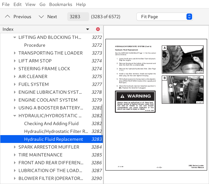
Hydraulic Fluid Replacement...392
Hydraulic / Hydrostatic Filter Replacement...392
SPARK ARRESTOR MUFFLER...393
FRONT & REAR AXLES...394
U-JOINTS...395
TIRE MAINTENANCE...395
Wheel Nuts...395
LOADER LUBRICATION...396
BACK-UP ALARM...397
OPERATOR CAB...397
HYDRAULIC SYSTEM...399
HYDRAULIC / HYDROSTATIC SCHEMATICS...402
TROUBLESHOOTING...423
HYDRAULIC SYSTEM INFORMATION...424
37° Flare Connections...424
Straight Thread O-Ring Fitting...424
Tubelines And Hoses...424
PORT BLOCK SERVICE...425
Bronze (40 Micron) Filter Replacement...425
Neutral By-Pass Valve Replacement...426
Cold Oil By-Pass Valve Replacement...426
OIL RESERVOIR...426
Oil Reservoir Removal...426
Oil Reservoir Installation...427
HYDRAULIC CONTROL VALVE (S/N 12999 & BELOW)...427
Hydraulic Control Valve Removal...427
Hydraulic Control Valve Disassembly...428
Inlet Section...429
Tilt Section...429
Lift Section...431
Auxiliary Section (For Older Style Control Valves)...434
Auxiliary Section (For Control Valves Equipped With Adjustable Detent)...436
Auxiliary Detent Adjustment...438
Hydraulic Control Valve Assembling...439
Hydraulic Control Valve Installation...439
HYDRAULIC CONTROL VALVE (S/N 13001 & ABOVE - MELROE VALVE)...440
Hydraulic Control Valve Removal...440
Hydraulic Control Valve Disassembly...441
Hydraulic Control Valve Inspection...444
Hydraulic Control Valve Assembling...444
Hydraulic Control Valve Installation...446
HYDRAULIC MAIN RELIEF VALVE...446
Hydraulic Main Relief Valve Testing...446
Hydraulic Main Relief Valve Replacement...447
Hydraulic Main Relief Valve Adjustment (S/N 12999 & Below)...448
Hydraulic Main Relief Valve Cleaning (S/N 13001 & Above)...448
Hydraulic Main Relief Valve Adjustment (S/N 13001 & Above)...448
HYDRAULIC PUMP...449
Checking Hydraulic Pump Pressure...449
Hydraulic Pump Removal...450
Hydraulic Pump Disassembly...450
Hydraulic Pump Inspection...451
Hydraulic Pump Assembling...451
Hydraulic Pump Installation...452
Checking Steering Relief Pressure...452
HYDRAULIC CYLINDERS...453
Checking Lift And Tilt Cylinder Seals...453
Checking Steering Cylinder Seals...454
Lift Cylinder Removal...454
Lift Cylinder Installation...455
Tilt Cylinder Removal...455
Tilt Cylinder Installation...456
Steering Cylinder Removal...456
Steering Cylinder Installation...457
Hydraulic Cylinder Disassembly...457
Hydraulic Cylinder Assembly...460
STEERING CONTROL VALVE...462
Steering Control Valve Removal...462
Steering Control Valve Disassembly...463
Steering Control Valve Inspection...465
Steering Control Valve Assembling...466
Steering Control Valve Installation...470
HYDROSTATIC SYSTEM...471
TROUBLESHOOTING...473
SERVO CONTROL...475
Servo Control Neutral Adjustment...475
Servo Control Removal...476
Servo Control Disassembly...477
Servo Control Assembling...478
Servo Control Installation (S/N 13033 & Below)...478
Servo Control Installation (S/N 13034 & Above)...479
FOOT PEDAL, PEDAL LOCK SYSTEM AND CENTERING MECHANISM...480
Foot Pedal Angle Adjustment...480
Seat Bar Assembly (S/N 13092 & Above)...481
Pedal Lock Cable...481
Centering Mechanism Removal...482
Centering Mechanism Spring Adjustment...483
S/N 13091 & Below...483
S/N 13092 & Above...483
Centering Mechanism Spring Replacement...484
S/N 13091 & Below...484
S/N 13092 & Above...485
Centering Mechanism Installation...486
Checking The Neutral Safety Switch...486
Neutral Safety Switch Adjustment...487
Micro Switch Adjustment...488
CHARGE PRESSURE AND REPLENISHING VALVES...490
Checking Charge Pressure...490
Checking Orifice In Charge Tubeline...490
Replenishing Valves...491
HYDROSTATIC PUMP...492
Hydrostatic Pump Removal...492
Hydrostatic Pump Disassembly...494
Hydrostatic Pump Inspection...497
Hydrostatic Pump Assembling...499
Hydrostatic Pump Installation On The Manifold Block...504
Hydrostatic Pump Installation...505
Hydrostatic Pump Start-Up Procedure...507
HYDROSTATIC MOTOR...508
Hydrostatic Motor Removal...508
Hydrostatic Motor Disassembly...509
Hydrostatic Motor Inspection...512
Hydrostatic Motor Assembly...513
Manifold block Disassembly...516
Manifold Block Assembling...516
Hydrostatic Motor Installation...516
Hydrostatic Motor Start-Up...517
Emergency Tow Valve...518
DRIVE SYSTEM...519
TROUBLESHOOTING THE DRIVE SYSTEM...521
DRIVE SHAFT...521
Drive Shaft Removal...521
Drive Shaft Installation...522
REAR AXLE...522
Rear Axle Removal...522
Rear Axle Installation...522
FRONT AXLE...523
Front Axle Removal...523
Front Axle Installation...523
AXLE AND DIFFERENTIAL DISASSEMBLY AND ASSEMBLY...524
Hub Removal...524
Hub Installation...525
Differential Assembly Removal...528
Ring Gear Removal...529
Ring Gear Installation...531
Clutch Plate Removal...531
Clutch Plate Installation...532
Drop Gear And Pinion Shaft Removal...533
Assembling Procedure Explanation...534
Checking Differential Assembly End Play (WITHOUT Pinion Shaft Installed)...535
Pinion Shaft Bearing Installation...536
Pinion Shaft Installation...537
Setting Pinion Shaft Position (Using Tool - Pinion Shaft NOT Installaed)...538
Setting Pinion Bearing Pre-Load...539
Differential Assembly Installation & Checking End Play (Pinion Shaft Installed)...541
Checking Gear Backlash...544
PARKING BRAKE (S/N 13060 & BELOW)...545
Description...545
Parking Brake Adjustment...545
Parking Brake Cable Removal...546
Parking Brake Cale Installation...546
Parking Brake Removal Fromm The Hydrostatic Motor...546
Parking Brake Installation On The Hydrostatic Motor...547
HYDRAULIC BRAKE (DUSCO) (S/N 13061 & ABOVE)...547
Description...547
Brake Removal (Dusco)...547
Brake Servicing (Dusco)...547
Brake Installation (Dusco)...549
Removing Air From The Brake System (Dusco)...550
Brake Valve Removal...550
Brake Valve Service...550
Brake Valve Installation...551
BRAKE (SY*TEC)...551
Removal And Installation...551
Disassembly And Assembly...551
MAIN FRAME...555
OPERATOR CAB...557
Operator Cab Removal...557
Operator Cab Installation...558
BOB-TACH...558
Checking Bob-Tach Wedges...559
Bob-Tach Removal...559
Bob-Tach Installation...560
FLOORPANEL...561
Floorpanel Removal...561
Floorpanel Installation...561
SEAT AND SEAT PLATE...561
Seat And Seat Plate Removal...561
Seat And Seat Plate Installation...562
FUEL TANK...562
Fuel Tank Removal...562
Fuel Tank Installation...563
DOORS...563
Rear Door Removal...563
Rear Door Installation...563
Side Door Removal...563
Side Door Installation...563
LOADER DISASSEMBLY AND ASSEMBLY...564
Seperating The Sections...564
Connecting The Sections...566
LIFT ARMS...567
Lift Arm Removal...567
Lift Arm Installation...567
ELECTRICAL SYSTEM...569
ELECTRICAL SCHEMATICS...571
ELECTRICAL SYSTEM...579
Description...579
TROUBLESHOOTING...579
BATTERIES...580
Checking The Batteries...580
Battery Safety Procedures...580
DIODES...581
Checking The Diodes...581
Diode Replacement...582
ALTERNATOR...582
Checking The Alternator...582
Alternator Removal...583
Alternator Service...584
Alternator Installation...585
STARTER...585
Checking The Starter...585
Starter Removal...586
Starter Service...586
Starter Installation...588
ENGINE SERVICE...589
ENGINE SERVICE (S/N 12999 & BELOW)...591
TROUBLESHOOTING...593
CHECKS AND ADJUSTMENTS...594
Oil Pressure...594
Valve Clearance...595
Engine Compression...595
Servicing The Air Cleaner...595
Throttle Linkage Adjustment...596
FUEL SYSTEM AND TIMING...596
FUEL FILTERS...597
Replacing The Final Fuel Filter Element...597
Cleaning The Water Filter Trap...597
REMOVING AIR FROM THE FUEL SYSTEM...597
FUEL LIFT PUMP...598
Checking The Lift Pump...598
Removing The Lift Pump...598
Installing The Lift Pump...598
FUEL INJECTION PUMP...598
Removing The Fuel Injection Pump...599
Installing The Fuel Injection Pump...599
Timing The Fuel Injection Pump (Using Dial Indicator)...599
Timing The Fuel Injection Pump (Using The Timing Tool)...600
Checking The Timing Mark On The Flange Injection Pump...601
FUEL INJECTOR NOZZLES...602
Removing Fuel Injector Nozzles...602
Checking Fuel Injector Nozzles...602
Installing Fuel Injector Nozzles...603
ENGINE...604
Removing The Engine...604
Installing The Engine...605
BLOWER HOUSING SHIELD...606
Removing The Blower Housing Shield...606
Installing The Blower Housing Shield...606
RADIATOR AND OIL COOLER ASSEMBLY...606
Cleaning Radiator And Oil Cooler Assembly...606
Removing Radiator And Oil Cooler Assembly...606
Installing Radiator And Oil Cooler Assembly...606
ENGINE BLOWER HOUSING...607
Installing The Engine Blower Housing...607
SPARK ARRESTOR MUFFLER...607
Cleaning The Muffler...607
Removing The Muffler...608
Installing The Muffler...608
CYLINDER HEAD...608
Removing The Cylinder Head...608
Removing Valves...609
Reconditioning The Valves And Valve SEATS...609
Installing Valve Guides...609
Checking Valve Springs...610
Combustion Chamber Inserts...611
Aligning Cylinder Head Surfaces...611
Installing Valves...611
Disassembling The Rocker Arms...612
Checking The Rocker Arms...613
Assembling The Rocker Arms...613
Installing The Cylinder Head...613
RECONDITIONING THE ENGINE...614
PISTONS AND CONNECTING RODS...614
Removing Pistons...614
Disassembling Pistons...615
Inspecting The Pistons...615
Installing Pistons To Connecting Rod...616
Installing Piston Assembly In The Engine Block...617
Installing New Pistons...617
CYLINDER LINERS...618
Checking Liners...618
Installing Liners...618
MAIN BEARINGS...619
Removing The Main Bearings...619
Installing The Main Bearings...619
Crankshaft End Play...620
CRANKSHAFT...620
Removing The Crankshaft...620
Checking The Crankshaft...621
Installing The Crankshaft...621
REAR MAIN BEARING OIL SEAL...622
Installing The Oil Seal...622
TIMING CASE AND GEARS...623
Removing The Timing Case Cover...623
Installing The Timing Case Cover...623
Removing The Front Seal...623
Installing The Front Seal...623
Removing The Idler Gear and Hub...624
Inspecting The Idler Gear And Hub...624
Installing The Idler Gear And Hub...624
Removing The Camshaft Gear...625
Installing The Camshaft Gear...625
Removing The Fuel Injection Pump...626
Installing The Fuel Injection Pump...626
Removing The Crankshaft Gear...626
Removing The Timing Case...626
Installing The Timing Case...626
Removing Camshaft And Tappets...627
Inspecting Camshaft And Tappets...627
Installing Camshaft And Tappets...628
LUBRICATION SYSTEM...628
Description Of The Lubrication System...628
Checking Engine Oil...629
Replacing Engine Oil And Filter...629
OIL PAN...629
Removing The Oil Pan...630
Installing The Oil Pan...630
OIL PUMP...630
Removing The Oil Pump...630
Disassembling The Oil Pump...630
Checking The Oil Pump...631
Assembling The Oil Pump...631
Installing The Oil Pump...631
OIL FILTER...632
Removing The Oil Filter...632
Disassembling The Oil Filter...632
COOLING SYSTEM...632
Belt For The Alternator And Water Pump...632
Coolant Level...632
Removing Coolant From The Cooling System...632
WATER PUMP...633
Removing The Water Pump...633
Disassembling The Water Pump...633
Checking The Water Pump...633
Assembling The Water Pump...633
Installing The Water Pump...634
THERMOSTAT...634
Removing The Thermostat...634
Checking The Thermostat...634
Installing The Thermostat...634
FLYWHEEL...635
Removing The Flywheel...635
Replacing The Flywheel Ring Gear...635
Installing The Flywheel...635
ENGINE SERVICE (S/N 13001 & ABOVE)...637
TROUBLSHOOTING...639
CHECKS AND ADJUSTMENTS...641
Serial Number...641
Oil Pressure...641
Valve Clearance...641
Check Engine Compression...641
FUEL SYSTEM AND TIMING...642
Fuel Filter...642
Removing Air From The Fuel System...642
Fuel Injection Pump...643
Removing The Fuel Injection Pump...643
Installing The Fuel Injection Pump...644
Timing The Fuel Injection Pump...645
Fuel Injector Nozzles...646
Removing The Fuel Injector Nozzles...647
Checking The Fuel Injector Nozzles...647
Installing The Fuel Injector Nozzles...648
High Pressure Fuel Lines...648
Glow Plugs...649
ENGINE AND ATTACHING PARTS...650
Removing The Engine...650
Installing The Engine...651
Blower Housing Shield...652
Removal...652
Installation...652
Engine Coolant Radiator ...652
Removal...652
Installation...653
Engine Blower Housing...653
Removal...653
Installation...653
Engine Muffler...654
Removal...654
Installation...654
Oil Cooler...654
Removing The Oil Cooler...654
Installing The Oil cooler...654
CYLINDER HEAD...655
Removing The Cylinder Head...655
Removal Of The Valves...655
Reconditioning The Valves And Valve Seats...656
Installing The Valve Guides...656
Checking Valve Springs...657
Combustion Chamber Inserts...658
Cylinder Head Inspection...658
Installation Of The Valves...659
Reconditioning The Rocker Arms...659
Disassembly...659
Checking...660
Assembly...660
Installing The Cylinder Head...660
RECONDITIONING THE ENGINE...662
Pistons And Connecting Rods...662
Removal...662
Disassembly...663
Inspection...663
Installation Of Piston To Connecting Rod...664
Installation Of Rings On The Piston...664
Installing Piston Assembly In The Engine Block...665
Cylinder Liners...665
Checking...665
Installation...666
Main Bearings...667
Removal...667
Installation...668
Crankshaft End Play...668
Crankshaft...668
Removal...668
Checking...669
Installation...670
Rear Main Bearing Oil Seal...670
TIMING CASE AND GEARS...671
Timing Case Cover...671
Removal...671
Installation...671
Front Seal...672
Removal...672
Installation...672
Idler Gear And Hub...672
Removal...672
Inspection...673
Installation...673
Camshaft Gear...673
Removal...674
Installation...674
Fuel Injection Pump Gear...674
Removal...674
Installation...674
Crankshaft Gear...675
Timing Case...675
Removal...675
Installation...675
Camshaft And Tappets...676
Removal...676
Inspection...677
Installation...677
LUBRICATION SYSTEM...677
Description Of The Lubrication System...677
Oil Pan...678
Removal...678
Installation...678
Oil Pump...679
Removal...679
Disassembly...679
Checking...680
Assembly...681
Installation...681
Oil Filter And Adapter Housing...682
Removal...682
Installation...682
COOLING SYSTEM...682
Alternator And Water Pump Belt...682
Water Pump...682
Removal...682
Installation...683
Thermostat...683
Removal...683
Testing The Thermostat...683
Installation...683
FLYWHEEL...684
Removal Of The Flywheel...684
Replacement Of The Flywheel Ring Gear...684
Installation Of The Flywheel...684
TECHNICAL DATA (S/N 12999 & BELOW)...685
LOADER SPECIFICATIONS...687
Specifications...687
Engine...687
Loader Hydraulics...688
Electrical...688
Drive System...688
Capacities...688
Tires...688
ENGINE SPECIFICATIONS...689
Cylinder Head Dimensions...689
pistons And Connecting Rod Dimensions...690
Cylinder Block And Liners Dimensions...691
Crankshaft And Main Bearings Dimesions...691
Timing Cse, Camshaft And Drive Dimensions...692
Oil Pump Dimensions...693
Cooling System And Water Pump Dimensions...694
Fuel System Specifications...694
De-Rating For Altitude...695
Engine Bolt Torque...695
Grinding Specifications For Crankshaft...696
Crankshaft Regrinding Data...696
HYDRAULIC SYSTEM...697
HYDROSTATIC SYSTEM...697
DECIMAL AND MILLIMETER EQUIVALENTS...698
U.S. TO METRIC CONVERSION...698
STANDARD TORQUE SPECIFICATIONS FOR BOLTS...699
TECHNICAL DATA (S/N 13001 & ABOVE)...701
LOADER SPECIFICATIONS...703
Specifications...703
Engine...703
Loader Hydraulics...704
Electrical...704
Drive System...704
Capacities...704
Tires...704
ENGINE SPECIFICATIONS...705
Cylinder Head Dimensions...705
Pistons And Connecting Rod Dimensions...705
Cylinder Block And Liner Dimensions...706
Crankshaft And Main Bearing Dimensions...707
Timing Case, Camshaft And Drive Dimensions...707
Oil Pump Dimensions...707
Cooling System And Water Pump Dimensions...708
Fuel System Specifications...708
De-Rating For Altitude...708
Engine Torque...709
Grinding Specifications For Crankshaft...710
Crankshaft Regrind Data...710
ALPHABETICAL INDEX...711
SERVICE MANUAL REVISIONS...715
2000-1...715
2000-2...717
2000-3...719
2000-4...721
6566180 (4-85) - 2000 Service Manual...723
MAINTENANCE SAFETY...725
CONTENTS...727
FOREWORD...727
SAFETY INSTRUCTIONS...729
Safety Is your Responsibility...729
Before You Operate The Bobcat Loader...729
Safe Operation needs A Qualified Operator...730
FIRE PREVENTION...730
SERIAL NUMBER LOCATIONS...731
Loader Serial Number...731
Engine Serial Number Locations...731
ARRIVAL CONDITION REPORT...731
DELIVERY REPORT...731
BOBCAT LOADER IDENTIFICATION...732
PREVENTIVE MAINTENANCE...733
SERVICE SCHEDULE...735
LIFT ARM STOP...736
FRAME LOCK...736
LIFTING AND BLOCKING THE LOADER...736
REAR DOOR...737
Door Latch Adjustment...737
AIR CLEANER...737
FUEL SYSTEM...738
Filling The Fuel Tank...738
Fuel Filter...739
Removing Air From The Fuel System...740
ENGINE LUBRICATION SYSTEM...740
Engine Oil And Filter Replacement...741
ENGINE COOLING SYSTEM...742
Coolant Level...742
Coolant Replacement...742
ALTERNATOR BELT ADJUSTMENT...742
ELECTRICAL SYSTEM...742
Electrical System Service...743
Using An Extra Battery (Jump Starting)...743
Battery Replacement...745
HYDRAULIC / HYDROSTATIC SYSTEM...745
Hydraulic/Hydrostatic Fluid Reservoir...745
Checking And Adding Fluid...745
Hydraulic Fluid Replacement...746
Hydraulic / Hydrostatic Filter Replacement...746
SPARK ARRESTOR MUFFLER...747
FRONT & REAR AXLES...748
U-JOINTS...749
TIRE MAINTENANCE...749
Wheel Nuts...749
LOADER LUBRICATION...750
BACK-UP ALARM...751
OPERATOR CAB...751
HYDRAULIC SYSTEM...753
HYDRAULIC / HYDROSTATIC SCHEMATICS...756
TROUBLESHOOTING...777
HYDRAULIC SYSTEM INFORMATION...778
37° Flare Connections...778
Straight Thread O-Ring Fitting...778
Tubelines And Hoses...778
PORT BLOCK SERVICE...779
Bronze (40 Micron) Filter Replacement...779
Neutral By-Pass Valve Replacement...780
Cold Oil By-Pass Valve Replacement...780
OIL RESERVOIR...780
Oil Reservoir Removal...780
Oil Reservoir Installation...781
HYDRAULIC CONTROL VALVE (S/N 12999 & BELOW)...781
Hydraulic Control Valve Removal...781
Hydraulic Control Valve Disassembly...782
Inlet Section...783
Tilt Section...783
Lift Section...785
Auxiliary Section (For Older Style Control Valves)...788
Auxiliary Section (For Control Valves Equipped With Adjustable Detent)...790
Auxiliary Detent Adjustment...792
Hydraulic Control Valve Assembling...793
Hydraulic Control Valve Installation...793
HYDRAULIC CONTROL VALVE (S/N 13001 & ABOVE - MELROE VALVE)...794
Hydraulic Control Valve Removal...794
Hydraulic Control Valve Disassembly...795
Hydraulic Control Valve Inspection...798
Hydraulic Control Valve Assembling...798
Hydraulic Control Valve Installation...800
HYDRAULIC MAIN RELIEF VALVE...800
Hydraulic Main Relief Valve Testing...800
Hydraulic Main Relief Valve Replacement...801
Hydraulic Main Relief Valve Adjustment (S/N 12999 & Below)...802
Hydraulic Main Relief Valve Cleaning (S/N 13001 & Above)...802
Hydraulic Main Relief Valve Adjustment (S/N 13001 & Above)...802
HYDRAULIC PUMP...803
Checking Hydraulic Pump Pressure...803
Hydraulic Pump Removal...804
Hydraulic Pump Disassembly...804
Hydraulic Pump Inspection...805
Hydraulic Pump Assembling...805
Hydraulic Pump Installation...806
Checking Steering Relief Pressure...806
HYDRAULIC CYLINDERS...807
Checking Lift And Tilt Cylinder Seals...807
Checking Steering Cylinder Seals...808
Lift Cylinder Removal...808
Lift Cylinder Installation...809
Tilt Cylinder Removal...809
Tilt Cylinder Installation...810
Steering Cylinder Removal...810
Steering Cylinder Installation...811
Hydraulic Cylinder Disassembly...811
Hydraulic Cylinder Assembly...814
STEERING CONTROL VALVE...816
Steering Control Valve Removal...816
Steering Control Valve Disassembly...817
Steering Control Valve Inspection...819
Steering Control Valve Assembling...820
Steering Control Valve Installation...824
HYDROSTATIC SYSTEM...825
TROUBLESHOOTING...827
SERVO CONTROL...829
Servo Control Neutral Adjustment...829
Servo Control Removal...830
Servo Control Disassembly...831
Servo Control Assembling...832
Servo Control Installation (S/N 13033 & Below)...832
Servo Control Installation (S/N 13034 & Above)...833
FOOT PEDAL, PEDAL LOCK SYSTEM AND CENTERING MECHANISM...834
Foot Pedal Angle Adjustment...834
Seat Bar Assembly (S/N 13092 & Above)...835
Pedal Lock Cable...835
Centering Mechanism Removal...836
Centering Mechanism Spring Adjustment...837
S/N 13091 & Below...837
S/N 13092 & Above...837
Centering Mechanism Spring Replacement...838
S/N 13091 & Below...838
S/N 13092 & Above...839
Centering Mechanism Installation...840
Checking The Neutral Safety Switch...840
Neutral Safety Switch Adjustment...841
Micro Switch Adjustment...842
CHARGE PRESSURE AND REPLENISHING VALVES...844
Checking Charge Pressure...844
Checking Orifice In Charge Tubeline...844
Replenishing Valves...845
HYDROSTATIC PUMP...846
Hydrostatic Pump Removal...846
Hydrostatic Pump Disassembly...848
Hydrostatic Pump Inspection...851
Hydrostatic Pump Assembling...853
Hydrostatic Pump Installation On The Manifold Block...858
Hydrostatic Pump Installation...859
Hydrostatic Pump Start-Up Procedure...861
HYDROSTATIC MOTOR...862
Hydrostatic Motor Removal...862
Hydrostatic Motor Disassembly...863
Hydrostatic Motor Inspection...866
Hydrostatic Motor Assembly...867
Manifold block Disassembly...870
Manifold Block Assembling...870
Hydrostatic Motor Installation...870
Hydrostatic Motor Start-Up...871
Emergency Tow Valve...872
DRIVE SYSTEM...873
TROUBLESHOOTING THE DRIVE SYSTEM...875
DRIVE SHAFT...875
Drive Shaft Removal...875
Drive Shaft Installation...876
REAR AXLE...876
Rear Axle Removal...876
Rear Axle Installation...876
FRONT AXLE...877
Front Axle Removal...877
Front Axle Installation...877
AXLE AND DIFFERENTIAL DISASSEMBLY AND ASSEMBLY...878
Hub Removal...878
Hub Installation...879
Differential Assembly Removal...882
Ring Gear Removal...883
Ring Gear Installation...885
Clutch Plate Removal...885
Clutch Plate Installation...886
Drop Gear And Pinion Shaft Removal...887
Assembling Procedure Explanation...888
Checking Differential Assembly End Play (WITHOUT Pinion Shaft Installed)...889
Pinion Shaft Bearing Installation...890
Pinion Shaft Installation...891
Setting Pinion Shaft Position (Using Tool - Pinion Shaft NOT Installaed)...892
Setting Pinion Bearing Pre-Load...893
Differential Assembly Installation & Checking End Play (Pinion Shaft Installed)...895
Checking Gear Backlash...898
PARKING BRAKE (S/N 13060 & BELOW)...899
Description...899
Parking Brake Adjustment...899
Parking Brake Cable Removal...900
Parking Brake Cale Installation...900
Parking Brake Removal Fromm The Hydrostatic Motor...900
Parking Brake Installation On The Hydrostatic Motor...901
HYDRAULIC BRAKE (DUSCO) (S/N 13061 & ABOVE)...901
Description...901
Brake Removal (Dusco)...901
Brake Servicing (Dusco)...901
Brake Installation (Dusco)...903
Removing Air From The Brake System (Dusco)...904
Brake Valve Removal...904
Brake Valve Service...904
Brake Valve Installation...905
BRAKE (SY*TEC)...905
Removal And Installation...905
Disassembly And Assembly...905
MAIN FRAME...909
OPERATOR CAB...911
Operator Cab Removal...911
Operator Cab Installation...912
BOB-TACH...912
Checking Bob-Tach Wedges...913
Bob-Tach Removal...913
Bob-Tach Installation...914
FLOORPANEL...915
Floorpanel Removal...915
Floorpanel Installation...915
SEAT AND SEAT PLATE...915
Seat And Seat Plate Removal...915
Seat And Seat Plate Installation...916
FUEL TANK...916
Fuel Tank Removal...916
Fuel Tank Installation...917
DOORS...917
Rear Door Removal...917
Rear Door Installation...917
Side Door Removal...917
Side Door Installation...917
LOADER DISASSEMBLY AND ASSEMBLY...918
Seperating The Sections...918
Connecting The Sections...920
LIFT ARMS...921
Lift Arm Removal...921
Lift Arm Installation...921
ELECTRICAL SYSTEM...923
ELECTRICAL SCHEMATICS...925
ELECTRICAL SYSTEM...933
Description...933
TROUBLESHOOTING...933
BATTERIES...934
Checking The Batteries...934
Battery Safety Procedures...934
DIODES...935
Checking The Diodes...935
Diode Replacement...936
ALTERNATOR...936
Checking The Alternator...936
Alternator Removal...937
Alternator Service...938
Alternator Installation...939
STARTER...939
Checking The Starter...939
Starter Removal...940
Starter Service...940
Starter Installation...942
ENGINE SERVICE...943
ENGINE SERVICE (S/N 12999 & BELOW)...945
TROUBLESHOOTING...947
CHECKS AND ADJUSTMENTS...948
Oil Pressure...948
Valve Clearance...949
Engine Compression...949
Servicing The Air Cleaner...949
Throttle Linkage Adjustment...950
FUEL SYSTEM AND TIMING...950
FUEL FILTERS...951
Replacing The Final Fuel Filter Element...951
Cleaning The Water Filter Trap...951
REMOVING AIR FROM THE FUEL SYSTEM...951
FUEL LIFT PUMP...952
Checking The Lift Pump...952
Removing The Lift Pump...952
Installing The Lift Pump...952
FUEL INJECTION PUMP...952
Removing The Fuel Injection Pump...953
Installing The Fuel Injection Pump...953
Timing The Fuel Injection Pump (Using Dial Indicator)...953
Timing The Fuel Injection Pump (Using The Timing Tool)...954
Checking The Timing Mark On The Flange Injection Pump...955
FUEL INJECTOR NOZZLES...956
Removing Fuel Injector Nozzles...956
Checking Fuel Injector Nozzles...956
Installing Fuel Injector Nozzles...957
ENGINE...958
Removing The Engine...958
Installing The Engine...959
BLOWER HOUSING SHIELD...960
Removing The Blower Housing Shield...960
Installing The Blower Housing Shield...960
RADIATOR AND OIL COOLER ASSEMBLY...960
Cleaning Radiator And Oil Cooler Assembly...960
Removing Radiator And Oil Cooler Assembly...960
Installing Radiator And Oil Cooler Assembly...960
ENGINE BLOWER HOUSING...961
Installing The Engine Blower Housing...961
SPARK ARRESTOR MUFFLER...961
Cleaning The Muffler...961
Removing The Muffler...962
Installing The Muffler...962
CYLINDER HEAD...962
Removing The Cylinder Head...962
Removing Valves...963
Reconditioning The Valves And Valve SEATS...963
Installing Valve Guides...963
Checking Valve Springs...964
Combustion Chamber Inserts...965
Aligning Cylinder Head Surfaces...965
Installing Valves...965
Disassembling The Rocker Arms...966
Checking The Rocker Arms...967
Assembling The Rocker Arms...967
Installing The Cylinder Head...967
RECONDITIONING THE ENGINE...968
PISTONS AND CONNECTING RODS...968
Removing Pistons...968
Disassembling Pistons...969
Inspecting The Pistons...969
Installing Pistons To Connecting Rod...970
Installing Piston Assembly In The Engine Block...971
Installing New Pistons...971
CYLINDER LINERS...972
Checking Liners...972
Installing Liners...972
MAIN BEARINGS...973
Removing The Main Bearings...973
Installing The Main Bearings...973
Crankshaft End Play...974
CRANKSHAFT...974
Removing The Crankshaft...974
Checking The Crankshaft...975
Installing The Crankshaft...975
REAR MAIN BEARING OIL SEAL...976
Installing The Oil Seal...976
TIMING CASE AND GEARS...977
Removing The Timing Case Cover...977
Installing The Timing Case Cover...977
Removing The Front Seal...977
Installing The Front Seal...977
Removing The Idler Gear and Hub...978
Inspecting The Idler Gear And Hub...978
Installing The Idler Gear And Hub...978
Removing The Camshaft Gear...979
Installing The Camshaft Gear...979
Removing The Fuel Injection Pump...980
Installing The Fuel Injection Pump...980
Removing The Crankshaft Gear...980
Removing The Timing Case...980
Installing The Timing Case...980
Removing Camshaft And Tappets...981
Inspecting Camshaft And Tappets...981
Installing Camshaft And Tappets...982
LUBRICATION SYSTEM...982
Description Of The Lubrication System...982
Checking Engine Oil...983
Replacing Engine Oil And Filter...983
OIL PAN...983
Removing The Oil Pan...984
Installing The Oil Pan...984
OIL PUMP...984
Removing The Oil Pump...984
Disassembling The Oil Pump...984
Checking The Oil Pump...985
Assembling The Oil Pump...985
Installing The Oil Pump...985
OIL FILTER...986
Removing The Oil Filter...986
Disassembling The Oil Filter...986
COOLING SYSTEM...986
Belt For The Alternator And Water Pump...986
Coolant Level...986
Removing Coolant From The Cooling System...986
WATER PUMP...987
Removing The Water Pump...987
Disassembling The Water Pump...987
Checking The Water Pump...987
Assembling The Water Pump...987
Installing The Water Pump...988
THERMOSTAT...988
Removing The Thermostat...988
Checking The Thermostat...988
Installing The Thermostat...988
FLYWHEEL...989
Removing The Flywheel...989
Replacing The Flywheel Ring Gear...989
Installing The Flywheel...989
ENGINE SERVICE (S/N 13001 & ABOVE)...991
TROUBLSHOOTING...993
CHECKS AND ADJUSTMENTS...995
Serial Number...995
Oil Pressure...995
Valve Clearance...995
Check Engine Compression...995
FUEL SYSTEM AND TIMING...996
Fuel Filter...996
Removing Air From The Fuel System...996
Fuel Injection Pump...997
Removing The Fuel Injection Pump...997
Installing The Fuel Injection Pump...998
Timing The Fuel Injection Pump...999
Fuel Injector Nozzles...1000
Removing The Fuel Injector Nozzles...1001
Checking The Fuel Injector Nozzles...1001
Installing The Fuel Injector Nozzles...1002
High Pressure Fuel Lines...1002
Glow Plugs...1003
ENGINE AND ATTACHING PARTS...1004
Removing The Engine...1004
Installing The Engine...1005
Blower Housing Shield...1006
Removal...1006
Installation...1006
Engine Coolant Radiator ...1006
Removal...1006
Installation...1007
Engine Blower Housing...1007
Removal...1007
Installation...1007
Engine Muffler...1008
Removal...1008
Installation...1008
Oil Cooler...1008
Removing The Oil Cooler...1008
Installing The Oil cooler...1008
CYLINDER HEAD...1009
Removing The Cylinder Head...1009
Removal Of The Valves...1009
Reconditioning The Valves And Valve Seats...1010
Installing The Valve Guides...1010
Checking Valve Springs...1011
Combustion Chamber Inserts...1012
Cylinder Head Inspection...1012
Installation Of The Valves...1013
Reconditioning The Rocker Arms...1013
Disassembly...1013
Checking...1014
Assembly...1014
Installing The Cylinder Head...1014
RECONDITIONING THE ENGINE...1016
Pistons And Connecting Rods...1016
Removal...1016
Disassembly...1017
Inspection...1017
Installation Of Piston To Connecting Rod...1018
Installation Of Rings On The Piston...1018
Installing Piston Assembly In The Engine Block...1019
Cylinder Liners...1019
Checking...1019
Installation...1020
Main Bearings...1021
Removal...1021
Installation...1022
Crankshaft End Play...1022
Crankshaft...1022
Removal...1022
Checking...1023
Installation...1024
Rear Main Bearing Oil Seal...1024
TIMING CASE AND GEARS...1025
Timing Case Cover...1025
Removal...1025
Installation...1025
Front Seal...1026
Removal...1026
Installation...1026
Idler Gear And Hub...1026
Removal...1026
Inspection...1027
Installation...1027
Camshaft Gear...1027
Removal...1028
Installation...1028
Fuel Injection Pump Gear...1028
Removal...1028
Installation...1028
Crankshaft Gear...1029
Timing Case...1029
Removal...1029
Installation...1029
Camshaft And Tappets...1030
Removal...1030
Inspection...1031
Installation...1031
LUBRICATION SYSTEM...1031
Description Of The Lubrication System...1031
Oil Pan...1032
Removal...1032
Installation...1032
Oil Pump...1033
Removal...1033
Disassembly...1033
Checking...1034
Assembly...1035
Installation...1035
Oil Filter And Adapter Housing...1036
Removal...1036
Installation...1036
COOLING SYSTEM...1036
Alternator And Water Pump Belt...1036
Water Pump...1036
Removal...1036
Installation...1037
Thermostat...1037
Removal...1037
Testing The Thermostat...1037
Installation...1037
FLYWHEEL...1038
Removal Of The Flywheel...1038
Replacement Of The Flywheel Ring Gear...1038
Installation Of The Flywheel...1038
TECHNICAL DATA (S/N 12999 & BELOW)...1039
LOADER SPECIFICATIONS...1041
Specifications...1041
Engine...1041
Loader Hydraulics...1042
Electrical...1042
Drive System...1042
Capacities...1042
Tires...1042
ENGINE SPECIFICATIONS...1043
Cylinder Head Dimensions...1043
pistons And Connecting Rod Dimensions...1044
Cylinder Block And Liners Dimensions...1045
Crankshaft And Main Bearings Dimesions...1045
Timing Cse, Camshaft And Drive Dimensions...1046
Oil Pump Dimensions...1047
Cooling System And Water Pump Dimensions...1048
Fuel System Specifications...1048
De-Rating For Altitude...1049
Engine Bolt Torque...1049
Grinding Specifications For Crankshaft...1050
Crankshaft Regrinding Data...1050
HYDRAULIC SYSTEM...1051
HYDROSTATIC SYSTEM...1051
DECIMAL AND MILLIMETER EQUIVALENTS...1052
U.S. TO METRIC CONVERSION...1052
STANDARD TORQUE SPECIFICATIONS FOR BOLTS...1053
TECHNICAL DATA (S/N 13001 & ABOVE)...1055
LOADER SPECIFICATIONS...1057
Specifications...1057
Engine...1057
Loader Hydraulics...1058
Electrical...1058
Drive System...1058
Capacities...1058
Tires...1058
ENGINE SPECIFICATIONS...1059
Cylinder Head Dimensions...1059
Pistons And Connecting Rod Dimensions...1059
Cylinder Block And Liner Dimensions...1060
Crankshaft And Main Bearing Dimensions...1061
Timing Case, Camshaft And Drive Dimensions...1061
Oil Pump Dimensions...1061
Cooling System And Water Pump Dimensions...1062
Fuel System Specifications...1062
De-Rating For Altitude...1062
Engine Torque...1063
Grinding Specifications For Crankshaft...1064
Crankshaft Regrind Data...1064
ALPHABETICAL INDEX...1065
SERVICE MANUAL REVISIONS...1069
2000-1...1069
2000-2...1071
2000-3...1073
6566182 (7-82) - 2000 Operator's Manual...1075
OPERATOR SAFETY WARNINGS...1076
DAFETY INSTRUCTIONS...1077
FOREWORD...1079
CONTENTS...1079
2000 BOBCAT LOADER IDENTIFICATION...1080
OPERATING INSTRUCTIONS...1081
OPERATING INSTRUCTIONS...1083
SAFETY SIGNS (DECALS)...1084
CONTROLS...1085
DASH PANEL...1085
THROTTLE CONTROL...1086
STOPPING THE ENGINE...1086
PARKING BRAKE...1086
STEERING AND SPEED CONTROLS...1087
HYDRAULIC CONTROLS...1088
LIFT ARM OPERATION...1088
TILT OPERATION...1088
AUXILIARY OPERATION...1089
BEFORE YOU START THE ENGINE...1089
STARTING THE ENGINE...1090
Normal Starting Condition...1091
Cold Temperature Starting Condition...1091
Cold Weather Starting Procedure...1092
BOBCAT LOADER OPERATION...1092
Bucket Size...1093
Installation Of Attachments...1093
Removal Of Attachments...1094
OPERATION OF THE BOBCAT LOADER...1094
OPERATING PROCEDURE...1094
Filling The Bucket...1097
Emptying The Bucket...1097
Digging Into The Ground...1097
Making The Ground Level...1097
Filling A Hole...1098
STOPPING THE BOBCAT LOADER...1098
TRANSPORTING THE BOBCAT LOADER...1098
EMERGENCY (TOW) VALVE...1100
FRONT WINDOW...1100
PREVENTIVE MAINTENANCE...1101
WARNINGS...1103
SERVICE SCHEDULE...1105
FRAME LOCK...1106
ENGINE SERVICE...1106
AIR CLEANER SERVICE...1106
FUEL SYSTEM...1107
FUEL SYSTEM SERVICE...1108
FUEL FILTERS...1108
REMOVING AIR FROM THE FUEL SYSTEM...1109
ENGINE LUBRICATION SYSTEM...1110
REPLACEMENT OF THE ENGINE OIL AND FILTER...1110
ENGINE COOLING SYSTEM...1111
Coolant Level...1111
Removing Coolant From The Cooling System...1111
ALTERNATOR...1111
Adjusting The Alternator Belt Tension...1111
ELECTRICAL SYSTEM...1112
USING AN EXTRA BATTERY (BOOSTER STARTING)...1114
TO INSTALL NEW BATTERIES...1115
HYDRAULIC/HYDROSTATIC SYSTEM...1116
HYDRAULIC / HYDROSTATIC FLUID RESERVOIR...1116
Checking And Adding Hydraulic / Hydrostatic Fluid...1118
Removing The Hydraulic / Hydrostatic Fluid...1118
REPLACEMENT OF THE HYDRAULIC / HYDROSTATIC FILTER...1118
FRONT & REAR AXLE...1119
U-JOINTS...1119
TIRE MAINTENANCE...1119
LUBRICATION OF THE BOBCAT LOADER...1120
SPARK ARRESTOR MUFFLER...1121
BOB-TACH...1121
LOADER SERIAL NUMBER...1121
OPERATOR GUARD...1122
DELIVERY REPORT...1122
THIRTY HOUR INSPECTION...1122
TROUBLESHOOTING...1123
TROUBLESHOOTING THE ENGINE...1125
TROUBLESHOOTING THE DRIVE SYSTEM...1126
TROUBLESHOOTING THE HYDRAULIC SYSTEM...1126
MAJOR PARTS...1127
MAIN FRAME...1129
FUEL TANK, SEAT & STEERING CONTROL...1130
DRIVE SYSTEM...1131
LIFT & TILT HYDRAULICS...1132
HYDROSTATIC CIRCUITRY...1133
OPERATOR GUARD ELECTRICAL...1135
ENGINE ELECTRICAL...1136
ENGINE & ATTACHING PARTS...1137
GENERAL INFORMATION...1139
SPECIFICATIONS...1141
ENGINE...1141
LOADER HYDRAULICS...1142
ELECTRICAL...1142
DRIVE SYSTEM...1142
CAPACITIES...1142
TIRES...1142
ADDITIONAL PUBLICATIONS...1143
WARRANTY...1145
6566396 (7-82) - 2000 RTF Operator's Manual...1147
WARNINGS...1148
SAFETY INSTRUCTIONS...1149
SAFETY IS YOUR RESPONSIBILITY...1149
BEFORE YOU OPERATE THE BOBCAT LOADER...1149
FOREWORD...1151
CONTENTS...1151
2000 BOBCAT ROUGH TERRAIN FORKLIFT IDENTIFICATION...1152
OPERATING INSTRUCTIONS...1153
OPERATING INSTRUCTIONS...1155
SAFETY SIGNS (DECALS) LOCATIONS...1156
DASH PANEL...1157
THROTTLE CONTROL...1158
STOPPING HTE ENGINE...1158
PARKING BRAKE...1158
STEERING AND SPEED CONTROLS...1159
HYDRAULIC CONTROLS...1160
VERTICAL LIFT OPERATION...1160
HYDRAULIC OPERATION...1160
BEFORE YOU START THE ENGINE...1160
STARTING THE ENGINE...1160
Normal Starting Condition...1162
Cold Temperature Starting Condition...1162
Cold Weather Starting Procedure...1163
ATTACHMENTS...1164
Pallet Forks...1164
Vertical Mast...1164
BOBCAT ROUGH TERRAIN FORKLIFT OPERATION...1165
OPERATING PROCEDURE...1165
Loading The Vertical Mast...1168
Unloading The Vertical Mast...1168
STOPPING THE BOBCAT ROUGH TERRAIN FORKLIFT...1168
TRANSPORTING THE BOBCAT ROUGH TERRAIN FORKLIFT...1169
EMERGENCY (TOW) VALVE...1170
FRONT WINDOW...1171
PREVENTIVE MAINTENANCE...1173
WARNINGS...1174
SERVICE SCHEDULE...1175
FRAME LOCK...1176
JACKING AND BLOCKING THE BOBCAT FORKLIFT...1176
ENGINE SERVICE...1177
ADJUSTING THE DOOR LATCH...1177
AIR CLEANER SERVICE...1177
FUEL SYSTEM...1178
FUEL SYSTEM SERVICE...1178
FUEL FILTERS...1179
REMOVING AIR FROM THE FUEL SYSTEM...1179
ENGINE LUBRICATION SYSTEM...1180
REPLACEMENT OF ENGINE OIL AND FILTER...1181
ENGINE COOLING SYSTEM...1182
Coolant Level...1182
REMOVING COOLANT FROM THE COOLING SYSTEM...1182
ALTERNATOR BELT...1182
ELECTRICAL SYSTEM...1182
USING AN EXTRA BATTERY (BOOSTER STARTING)...1185
INSTALLING NEW BATTERIES...1186
HYDRAULIC / HYDROSTATIC SYSTEM...1187
HYDRAULIC / HYDROSTATIC FLUID RESERVOIR...1187
Checking And Adding Hydraulic / Hydrostatic Fluid...1189
Removing Hydraulic / Hydrostatic Fluid...1189
REPLACEMENT OF THE HYDRAULIC / HYDROSTATIC FILTER...1189
FRONT AND REAR AXLES...1190
U-JOINTS...1190
TIRE MAINTENANCE...1190
LUBRICATION OF THE BOBCAT ROUGH TERRAIN FORKLIFT...1191
SPARK ARRESTOR MUFFLER...1192
BACK-UP ALARM...1193
VERTICAL MAST...1193
SERIAL NUMBER LOCATIONS...1193
OPERATOR CAB...1193
DELIVERY REPORT...1193
TROUBLESHOOTING...1195
TROUBLESHOOTING THE ENGINE...1197
TROUBLESHOOTING THE HYDRAULIC SYSTEM...1199
TROUBLESHOOTING THE HYDROSTATIC SYSTEM...1198
TROUBLESHOOTING THE VERTICAL MAST...1200
MAJOR PARTS...1201
MAIN FRAME...1203
FUEL TANK, SEAT & STEERING CONTROL...1204
DRIVE SYSTEM...1205
BRAKE SYSTEM...1206
HYDROSTATIC SYSTEM...1207
OPERATOR GUARD ELECTRICAL...1209
ENGINE ELECTRICAL...1210
ENGINE & ATTACHING PARTS...1211
GENERAL INFORMATION...1213
SPECIFICATIONS...1215
VERTICAL MAST...1215
ENGINE...1215
LOADER HYDRAULICS...1216
ELECTRICAL...1216
DRIVE SYSTEM...1216
CAPACITIES...1216
TIRES...1216
WARRANTY...1217
6566459 (2-83) - 2000 Operation & Maintenance Manual...1219
WARNINGS...1220
SAFETY INSTRUCTIONS...1221
SAFETY IS YOUR RESPONSIBILITY...1221
BEFORE YOU OPERATE THE BOBCAT LOADER...1221
SERIAL NUMBER LOCATIONS...1222
Loader Serial Number...1222
Engine Serial Number...1222
FOREWORD...1223
CONTENTS...1223
2000 BOBCAT LOADER IDENTIFICATION...1224
OPERATING INSTRUCTIONS...1225
OPERATING INSTRUCTIONS...1227
MACHINE SIGNS (DECALS)...1228
OPERATING CONDITIONS...1230
CONTROLS...1230
DASH PANEL...1230
THROTTLE CONTROL...1231
STOPPING THE ENGINE...1231
PARKING BRAKE...1231
STEERING AND SPEED CONTROLS...1232
HYDRAULIC CONTROLS...1233
LIFT ARM OPERATION...1233
TILT OPERATION...1233
AUXILIARY OPERATION...1234
BEFORE YOU START THE ENGINE...1234
STARTING THE ENGINE...1235
Normal Starting Condition...1236
Cold Temperature Starting Condition...1236
Cold Weather Starting Procedure...1237
ATTACHMENTS & BUCKETS ...1237
Installation Of Attachments...1238
Removal Of Attachments...1239
OPERATION OF THE BOBCAT LOADER...1239
OPERATING PROCEDURE...1239
Filling The Bucket...1242
Emptying The Bucket...1242
Digging Into The Ground...1242
Making The Ground Level...1242
Filling A Hole...1243
STOPPING THE BOBCAT LOADER...1243
TRANSPORTING THE BOBCAT LOADER...1243
EMERGENCY (TOW) VALVE...1245
FRONT WINDOW...1245
PREVENTIVE MAINTENANCE...1247
WARNINGS...1248
SERVICE SCHEDULE...1249
FRAME LOCK...1250
LIFTING AND BLOCKING THE BOBCAT LOADER...1250
ENGINE SERVICE...1251
ADJUSTING THE DOOR LATCH...1251
AIR CLEANER SERVICE...1251
FUEL SYSTEM...1252
FUEL SYSTEM SERVICE...1252
FUEL FILTER...1253
REMOVING AIR FROM THE FUEL SYSTEM...1253
ENGINE LUBRICATION SYSTEM...1254
REPLACEMENT OF ENGINE OIL AND FILTER...1255
ENGINE COOLING SYSTEM...1256
Coolant level...1256
REMOVING COOLANT FROM THE COOLING SYSTEM...1256
ALTERNATOR BELT...1256
ELECTRICAL SYSTEM...1256
USING AN EXTRA BATTERY (BOOSTER STARTING)...1259
INSTALLING A NEW BATTERY...1260
HYDRAULIC / HYDROSTTATIC SYSTEM...1261
HYDRAULIC / HYDROSTATIC FLUID RESERVOIR...1261
Checking And Adding Hydraulic / Hydrostatic Fluid...1263
Removing The Hydraulic/Hydrostatic Fluid...1263
REPLACEMENT OF THE HYDRAULIC / HYDROSTATIC FILTER...1263
FRONT & REAR AXLES...1264
U-JOINTS...1264
TIRE MAINTENANCE...1264
Tire Rotation...1265
Wheel Nuts...1265
LUBRICATION OF THE BOBCAT LOADER...1266
SPARK ARRESTOR MUFFLER...1267
BOB-TACH...1268
BACK-UP ALARM...1268
OPERATOR CAB (ROPS & FOPS)...1268
DELIVERY REPORT...1268
TROUBLESHOOTING...1269
TROUBLESHOOTING THE ENGINE...1271
TROUBLESHOOTING THE HYDROSTATIC SYSTEM...1272
TROUBLESHOOTING THE HYDRAULIC SYSTEM...1273
MAJOR PARTS...1275
MAIN FRAME...1277
FUEL TANK, SEAT & STEERING CONTROL...1278
DRIVE SYSTEM...1279
BRAKE SYSTEM...1280
HYDROSTATIC CIRCUITRY...1281
OPERATOR GUARD ELECTRICAL...1283
ENGINE ELECTRICAL...1284
ENGINE & ATTACHING PARTS...1285
WARNING SIGNS...1287
WARNING - 6563484...1289
SERVICE SCHEDULE - 6585084...1290
WARNING - 6584333...1292
WARNING - 6584243...1293
IMPORTANT - 6560573...1294
GENERAL INFORMATION...1295
OPERATION AND PERFORMANCE...1297
ENGINE...1297
HYDRAULICS...1298
ELECTRICAL...1298
DRIVE SYSTEM...1298
CAPACITIES...1298
TIRES...1298
ADDITIONAL PUBLICATIONS...1299
WARRANTY...1301
6566662 (11-88) - 2000 RTF Service Manual...1303
WARNINGS...1304
SAFETY NSTRUCTIONS...1305
Safety Is Your Responsibility...1305
Safe Operation Needs A Qualified Operator...1306
CONTENTS...1307
FOREWORD...1307
PREVENTIVE MAINTENANCE...1309
FRAME LOCK...1311
LIFTING AND BLOCKING THE BOBCAT FORKLIFT...1311
SERIAL NUMBER LOCATIONS...1312
Machine Serial Number...1312
Engine Serial Number...1312
Vertical Mast Serial Number...1312
Axle Serial Numbers...1312
DELIVERY REPORT...1312
SERVICE SCHEDULE...1313
ENGINE SERICE...1314
ADJUSTING THE DOOR LATCH...1314
AIR CLEANER SERVICE...1314
FUEL SYSTEM...1315
Removing Air From The Fuel System...1316
Fuel System Service...1315
Fuel Filter...1316
ENGINE LUBRICATION SYSTEM...1317
Replacement Of Engine Oil And Filter...1318
ENGINE COOLING SYSTEM...1319
Coolant Level...1319
Removing Coolant From The Cooling System...1319
ALTERNATOR BELT...1319
ELECTRICAL SYSTEM...1319
Operator Guard Electrical Circuitry...1320
Engine Electrical Circuitry...1321
Using An Extra Battery (Booster Starting)...1322
New Battery Installation...1323
HYDRAULIC/HYDROSTATIC SYSTEM...1324
Hydraulic/Hydrostatic Fluid Reservoir...1324
Checking And Adding Hydraulic/Hydrostatic Fluid...1326
Replacement Of The Hydraulic/Hydrostatic Filter...1326
FRONT & REAR AXLE...1327
U-JOINTS...1327
TIRE MAINTENANCE...1328
Tire Rotation...1328
Wheel Nuts...1328
LUBRICATION OF THE BOBCAT ROUGH TERRAING FORKLIFT...1329
SPARK ARRESTOR MUFFLER...1330
BACK-UP ALARM...1331
VERTICAL MAST...1331
OPERATOR CAB...1331
HYDRAULIC SYSTEM...1333
HYDRAULIC/HYDROSTATIC SCHEMATICS...1335
HYDRAULIC SYSTEM OPERATIONS...1343
Description...1343
Flow Chart...1343
TROUBLESHOOTING...1344
HYDRAULIC SYSTEM OPERATION...1345
37° Flare Connections...1345
Straight Thread O-Ring Fitting...1345
Tubelines And Hoses...1345
HYDRAULIC SYSTEM SERVICE...1346
Checking And Adding Hydraulic Fluid...1346
Replacing The Hydraulic Fluid...1346
Replacing The Hydraulic Fluid Filters...1347
Replacing The Bronze (40 Micron) Filter...1347
Replacing The Neutral By-Pass Valve...1348
Replacing The Cold Weather By-Pass Valve...1349
OIL RESERVOIR...1349
Removing The Oil Reservoir...1349
Installing The Oil Reservoir...1349
HYDRAULIC CONTROL VALVE...1350
Description Of The Control Valve...1350
Removing The Hydraulic Control Valve...1351
Disassembly Of The Control Valve...1352
Inspection Of The Control Valve...1354
Reassembly Of The Control Valve...1354
Installing The Control Valve...1355
HYDRAULIC MAIN RELIEF VALVE...1355
Checking The Hydraulic Main Relief Valve...1355
Replacing The Hydraulic Main Relief Valve...1357
HYDRAULIC PUMP...1357
Checking The Hydraulic Pump Pressure...1357
Removing The Hydraulic Pump...1358
Disassembly Of The Hydraulic Pump...1359
Inspection Of The Hydraulic Pump...1360
Assembly Of The Hydraulic Pump...1360
Installing The Hydraulic Pump...1361
Checking Steering Relief Pressure...1361
COUNTERBALANCE VALVE...1362
HYDRAULIC CYLINDERS...1362
Checking The Lift Cylinder Seals...1362
Checking The Tilt Cylinder Seals...1363
Checking The Steering Cylinder Seals...1364
Removing The Lift Cylinder...1364
Inspecting The Lift Cylinder...1366
Installing The Lift Cylinder...1366
Removing The Tilt Cylinders...1366
Installing The Tilt Cylinders...1367
Removing The Steering Cylinder...1368
Installing The Steering Cylinder...1368
Disassembly Of The Hydrailic Cylinder...1368
Assembly Of The Hydraulic Cylinder...1371
STEERING CONTROL VALVE...1372
Removing The Steering Control Valve...1373
Disassembly Of The Steering Control Valve...1373
Inspection Of The Steering Control Valve...1376
Assembly Of The Steering Control Valve...1377
Installing The Steering Control Valve...1381
HYDROSTATIC SYSTEM...1383
SYSTEM OPERATIONS DESCRIPTION...1385
TROUBLESHOOTING...1386
SERVO CONTROL...1388
Neutral Adjustment For Servo Control...1388
Removing The Servo Control...1389
Disassembly Of The Servo Control...1389
Assembly Of The Servo Control...1390
Installing The Servo Control...1390
FOOT PEDAL AND CENTERING MECHANISM...1391
Removing The Centering Mechanism...1391
Adjusting The Springs In The Centering Mechanism...1391
Replacing The Springs On The Centering Mechanism...1392
Installing The Centering Mechanism...1393
Adjusting The Neutral Safety Start Switch...1393
CHARGE PRESSURE AND REPLENISHING VALVES...1394
Checking The Charge Pressure...1394
Checking Orifice In Charge Tubeline...1394
Replenishing Valves...1395
HYDROSTATIC PUMP...1396
Removing The Hydrostatic Pump...1396
Disassembly Of The Hydrostaic Pumps...1398
Hydrostatic Pump Inspection...1401
Assembly Of The Hydrostatic Pump...1403
Installing Pumps To The Manifold Block...1407
Hydrostatic Pump Installation...1408
Hydrostatic Pump Start-Up Procedure...1410
HYDROSTATIC MOTOR...1410
Hydrostatic Motor Removal...1411
Hydrostatic Motor Disassembly...1411
Inspection Of The Hydrostatic Motor...1414
Assembling The The Hydrostatic Motor...1415
Manifold Block Disassembly...1419
Manifold Block Assembly...1419
Hydrostatic Motor Installation...1419
Hydrostatic Motor Start-Up...1420
Tow Valves...1420
DRIVE SYSTEM...1421
DESCRIPTION...1423
DIFFERENTIAL OIL LEVEL...1423
LUBRICATING THE U-JOINTS...1423
DRIVE SHAFT...1423
Removing The Drive Shaft...1423
Installing The Drive Shaft...1424
REAR AXLE...1424
Description...1424
Removing The Rear Axle...1424
Installing The Rear Axle...1425
FRONT AXLE...1425
Description...1425
Removing The Front Axle...1425
Installing The Front Axle...1425
DISASSEMBLING AND ASSEMBLING AXLES...1426
Removing Hubs...1426
Installing Hubs...1427
Removing The Differential Assembly...1429
Removing The Ring Gear...1430
Installing The Ring Gear...1431
Removing Clutch Plates...1432
Installing Clutch Plates...1433
Explanation Of Assembly Procedure...1434
Removing The Drop Gear And Pinion Shaft...1433
Checking Differential Assembly End Play (WITHOUT Pinion Shaft Installed)...1435
Installing The Pinion Shaft Bearings...1436
Installing The Pinion Shaft ...1436
Setting Pinion Shaft position (Using Tool - Pinion Shaft NOT Installed)...1437
Setting Pinion Bearing Pre-Load...1438
Installing Differential Assembly & Checking end Play (Pinion Shaft Installed)...1440
Checking Gear Backlash...1443
PARKING BRAKE...1444
Description...1444
Adjusting The Parking Brake...1444
Removing The Parking Brake Cable...1445
Installing The Parking Brake Cable...1445
Removing The Parking Brake Assembly From The Hydrostatic Motor...1445
Installing The Parking Brake Assembly On The Hydrostatic Motor Housing...1446
MAIN FRAME...1447
OPERATOR CAB...1449
REAR GRILL...1449
Removing The Rear Grill...1449
Installing The Rear Grill...1449
FLOORPANELS...1449
Removing The Floorpanels...1449
Installing The Floorpanels...1449
SEAT AND SEAT PLATE...1450
Removing The Seat And Seat Plate...1450
Installing The Seat And Seat Plate...1450
FUEL TANK...1451
Removing The Fuel Tank...1451
Installing The Fuel Tank...1451
DOORS...1451
Removing The Rear door...1451
Installing The Rear Door...1451
Removing The Side Doors...1452
Installing The Side Doors...1452
DISASSEMBLING THE BOBCAT FORKLIFT...1452
Seperating The Sections...1452
Ball Stud & Race Assembly...1453
Removing The Oscillating Link...1453
ASSEMBLING THE BOBCAT FORKLIFT...1454
VERTICAL MAST...1455
TROUBLESHOOTING THE VERTICAL MAST...1457
REMOVING THE VERTICAL MAST...1457
INSTALLING THE VERTICAL MAST...1458
INSPECTING THE VERTICAL MAST...1459
REPLACING THE BRONZE BUSHING...1460
REMOVING THE MOUNTING FRAME...1460
INSTALLING THE MOUNTING FRAME...1461
REMOVING THE CARRIAGE CHAINS...1461
INSTALLING THE CARRIAGE CHAINS...1461
ADJUSTING THE LIFT CARRIAGE...1462
REMOVING THE LIFT CARRIAGE...1462
INSTALLING THE LIFT CARRIAGE...1463
ADJUSTING THE CARRIAGE ROLLERS...1463
PALLET FORKS...1466
Installing The Pallet Forks...1466
Removing The Pallet Forks...1466
Adjusting The Pallet Forks...1466
ELECTRICAL SYSTEM...1467
ELECTRICAL SCHEMATICS...1469
DESCRIPTION...1477
Dash Panel...1477
Wiring Diagrams...1477
SERVICING THE ELECTRICAL SYSTEM...1478
Cautions To Be Taken In Use Of The Alternator...1478
General Servicing...1478
Charging The Batteries...1478
TROUBLESHOOTING THE ELECTRICAL SYSTEM...1479
CHECKING THE BATTERIES...1479
REPLACING THE BATTERIES...1479
WIRING HARNESS DIODES...1480
Description...1480
Checking The Diodes...1480
Replacing The Diodes...1480
NEUTRAL START SAFETY SWITCH...1480
Checking The Neutral Start Safety Switch...1480
ALTERNATOR...1481
Description...1481
Adjusting Or Replacing The Alternator Belt...1481
Checking Alternator Wiring...1481
Checking Alternator Output...1482
Checking The Regulator...1482
Removing The Alternator...1482
Disassembling The Alternator...1482
Checking The Rotor...1483
Checking The Stator...1483
Checking Diode Trio...1484
Checking Rectifier...1484
Assembling And Installing The Alternator...1484
STARTER...1484
Description...1484
Checking Starter...1485
Removing Starter...1485
Disassembling The Starter...1485
Cleaning And Inspecting The Starter...1486
Replacing The Brushes...1486
Assembling The Starter...1486
BACK-UP ALARM...1487
ENGINE SERVICE...1489
TROUBLESHOOTING...1491
CHECKS & ADJUSTMENTS...1493
Oil Pressure...1493
Valve Clearance...1493
Check Engine Compression...1493
FUEL SYSTEM AND TIMING...1494
Fuel Injection Pump...1494
Removing The Fuel Injection Pump...1494
Installing The Fuel Injection Pump...1495
Timing The Fuel Injection Pump...1496
Fuel Injector Nozzles...1497
Removing Fuel Injector Nozzles...1498
Checking The Fuel Injector Nozzles...1498
Installing The Fuel Injector Nozzles...1499
High Pressure Fuel Lines...1499
Glow Plugs...1500
ENGINE AND ATTACHING PARTS...1501
Removing The Engine...1501
Installing The Engine...1502
Blower Housing Shield...1503
Removal...1503
Installation...1503
Engine Coolant Radiator...1503
Removal...1503
Installation...1504
Engine Blower Housing...1504
Removal...1504
Installation...1504
Engine Muffler...1505
Removal...1505
Installation...1505
Oil Cooler...1505
Installing The Oil Cooler...1505
Removing The Oil Cooler...1505
CYLINDER HEAD...1506
Removing The Cylinder Head...1506
Removal Of The Valves...1506
Reconditioning The Valves And Valve Seats...1507
Installing Valve Guides...1507
Checking Valve Springs...1508
Combustion Chamber Inserts...1509
Cylinder Head Inspection...1509
Installation Of The Valves...1510
Reconditioning The Rocker Arms...1510
Disassembly...1510
Checking...1511
Assembly...1511
Installing The Cylinder Head...1511
RECONDITIONING THE ENGINE...1513
Pistons And Connecting Rods...1513
Removal...1513
Disassembly...1514
Inspection...1514
Installation Of Piston To Connecting Rod...1515
Installation Of Rings On The Piston...1515
Installing Piston Assembly In The Engine Block...1516
Cylinder Liners...1516
Checking...1516
Installation...1517
Main Bearings...1518
Removal...1518
Installation...1519
Crankshaft End Play...1519
Crankshaft...1519
Removal...1519
Checking...1520
Installation...1521
Rear Main Bearing Oil Seal...1521
TIMING CASE AND GEARS...1522
Timing Case Cover...1522
Removal...1522
Installation...1522
Front Seal...1523
Removal...1523
Installation...1523
Idler Gear And Hub...1523
Removal...1523
Inspection...1524
Installation...1524
Camshaft Gear...1524
Removal...1525
Installation...1525
Fuel Injection Pump Gear...1525
Removal...1525
Installation...1525
Crankshaft Gear...1526
Timing Case...1526
Removal...1526
Installation...1526
Camshaft And Tappets...1527
Removal...1527
Inspection...1528
Installation...1528
LUBRICATION SYSTEM...1528
Description Of The Lubrication System...1528
Oil Pan...1529
Removal...1529
Installation...1529
Oil Pump...1530
Removal...1530
Disassembly...1530
Checking...1531
Assembly...1532
Installation...1532
Oil Filter And Adapter Housing...1533
Removal...1533
Installation...1533
COOLING SYSTEM...1533
Alternator And Water Pump Belt...1533
Water Pump...1533
Removal...1533
Installation...1534
Thermostat...1534
Removal...1534
Testing The Thermostat...1534
Installation...1534
FLYWHEEL...1535
Removal Of The Flywheel...1535
Replace The Flywheel Ring Gear...1535
Installation Of The Flywheel...1535
TECHNICAL DATA...1537
FORKLIFT SPECIFICATIONS...1539
Specifications...1539
Vertical Mast...1539
Engine...1539
Hydraulics...1540
Electrical...1540
Drive System...1540
Capacities...1540
Tires...1540
ENGINE SPECIFICATIONS...1541
Cylinder Head Dimensions...1541
Pistons And Connecting Rod Dimensions...1541
Cylinder Block And Liner Dimensions...1542
Crankshaft And Main Bearing Dimensions...1542
Timing Case, Camshaft And Drive Dimensions...1543
Oil Pump Dimensions...1543
Cooling System And Water Pump Dimensions...1543
Fuel System Specifications...1544
De-Rating For Altitude...1544
Engine Torque...1544
Grinding Specifications For Crankshaft...1545
Crankshaft Regrind Data...1545
HYDRAULIC SYSTEM...1546
HYDROSTATIC SYSTEM...1546
DECIMAL AND MILLIMETER EQUIVALENTS...1547
U.S. TO METRIC CONVERSION...1547
STANDARD TORQUE SPECIFICATIONS FOR BOLTS...1548
ALPHABETICAL INDEX...1549
6566662 (4-83) - 2000 RTF Service Manual...1555
6566667 (2-86) - 1600 Operator's Manual...1804
WARNINGS...1806
SAFETY INSTRUCTIONS...1808
SAFETY IS YOUR RESPONSIBILITY...1808
BEFORE YOU OPERATE THE BOBCAT LOADER...1808
SAFE OPERATION NEEDS A QUALIFIED OPERATOR...1809
SERIAL NUMBER LOCATIONS...1809
Loader Serial Number...1809
Engine Serial Number...1809
DELIVERY REPORT...1809
FOREWORD...1810
CONTENTS...1810
REFERENCE INFORMATION...1810
1600 BOBCAT LOADER IDENTIFICATION...1811
OPERATING INSTRUCTIONS...1812
OPERATING INSTRUCTIONS...1814
MACHINE SIGNS (DECALS) LOCATIONS...1815
OPERATING CONDITIONS...1815
CONTROLS...1818
DASH PANEL...1818
THROTTLE CONTROL...1819
STOPPING THE ENGINE...1819
PARKING BRAKE...1819
STEERING AND SPEED CONTROLS...1820
HYDRAULIC CONTROLS...1821
LIFT ARM OPERATION...1821
TILT OPERATION...1821
AUXILIARY HYDRAULICS OPERATION...1821
BEFORE YOU START THE ENGINE...1822
STARTING THE ENGINE...1823
Normal Starting Conditions...1823
Cold Temperature Starting Condition...1824
Cold Weather Starting Procedure...1825
ATTACHMENTS AND BUCKETS FOR THE BOBCAT LOADER...1826
Installaing Attachments...1826
Removing Attachments...1827
OPERATING PROCEDURE...1827
Emptying The Bucket...1830
Digging Into The Ground...1830
Leveling The Ground...1830
Filling A Hole...1831
PARKING THE LOADER...1831
TOWING THE LOADER...1831
Tow Valve...1831
Brake Release...1831
TRANSPORTING THE BOBCAT LOADER...1832
LIFT ARM STOP...1833
FRONT & REAR WINDOWS...1833
PREVENTIVE MAINTENANCE...1834
WARNINGS...1835
SERVICE SCHEDULE...1836
FRAME LOCK...1837
ENGINE SERVICE...1837
ADJUSTING THE DOOR LATCH...1838
AIR CLEANER SERVICE...1838
FUEL SYSTEM...1839
FUEL SYSTEM SERVICE...1839
FUEL FILTER...1840
REMOVING AIR FROM THE FUEL SYSTEM...1840
ENGINE LUBRICATION SYSTEM...1841
ENGINE OIL AND FILTER REPLACEMENT...1841
ENGINE COOLING SYSTEM...1842
Coolant Level...1842
REMOVING COOLANT FROM THE COOLING SYSTEM...1842
ADJUSTING THE ALTERNATOR BELT...1843
OPERATOR CAB ELECTRICAL...1844
ENGINE ELECTRICAL...1845
ELECTRICAL SYSTEM...1846
USING AN EXTRA BATTERY TO START ENGINE...1846
INSTALLING A NEW BATTERY...1848
HYDRAULIC/HYDROSTATIC SYSTEM...1849
HYDRAULIC / HYDROSTATIC FLUID RESERVOIR...1850
Checking And Adding Hydraulic / Hydrostatic Fluid...1850
Removing The Hydraulic / Hydrostatic Fluid...1850
HYDRAULIC / HYDROSTATIC FILTER REPLACEMENT...1850
FRONT & REAR AXLES...1851
U-JOINTS...1851
TIRE MAINTENANCE...1851
Tire Rotation...1852
Wheel nuts...1852
BOBCAT LOADER LUBRICATION...1853
SPARK ARRESTOR MUFFLER...1854
BOB-TACH...1855
BACK-UP ALARM...1855
OPERATOR CAB (ROPS)...1855
GENERAL INFORMATION...1856
LOADER SPECIFICATIONS...1858
OPERATION & PERFORMANCE...1858
ENGINE...1858
HYDRAULICS...1859
ELECTRICAL...1859
DRIVE SYSTEM...1859
CAPACITIES...1859
TIRES...1859
WARRANTY...1860
6566671 (9-96) - 2000 Operation & Maintenance Manual...1862
OPERATOR SAFETY WARNINGS...1864
FOREWORD...1866
CONTENTS...1866
SAFETY INSTRUCTIONS...1868
SAFETY IS YOUR RESPONSIBILITY...1868
BEFORE YOU OPERATE THE BOBCAT LOADER...1868
SAFE OPERATION NEED A QUALIFIED OPERATOR...1869
FIRE PREVENTION...1869
SERIAL NUMBER LOCATIONS...1870
DELIVERY REPORT...1870
BOBCAT LOADER IDENTIFICATION...1871
OPERATING INSTRUCTIONS...1872
OPERATING INSTRUCTIONS...1874
GETTING ON AND OFF THE LOADER...1874
MACHINE SIGNS (DECALS)...1875
LEARNING THE CONTROLS...1875
DASH PANEL...1878
THROTTLE CONTROL...1878
PARKING BRAKE...1878
STEERING AND SPEED CONTROLS...1879
HYDRAULIC CONTROLS...1880
Lift Arm Operation...1880
Tilt Operation...1880
Hydraulic Operation...1880
Auxiliary Operation...1880
BEFORE STARTING THE ENGINE...1881
STARTING THE ENGINE...1882
Cold Temperature Starting...1884
ATTACHMENTS AND BUCKETS...1884
Bucket Or Fork Installation...1885
Bucket Or Fork Removal...1886
OPERATING PROCEDURES...1886
Filling The Bucket...1888
Emptying The Bucket...1888
Digging Into The Ground...1888
Leveling The Ground (Using Float Position For The Lift Arms)...1889
Backfilling...1890
STOPPING THE ENGINE AND PARKING THE LOADER...1890
TRANSPORTING THE BOBCAT LOADER...1890
EMERGENCY (TOW) VALVE...1891
FRONT AND REAR WINDOWS...1892
OPERATOR RESTRAINT SYSTEM...1893
Inspection Of The Operator Restraint System...1893
Service Of The Operator Restraint System...1893
PREVENTIVE MAINTENANCE...1894
MAINTENANCE SAFETY...1895
SERVICE SCHEDULE...1896
LIFT ARM STOP...1897
FRAME LOCK...1897
REAR DOOR...1897
Door Latch Adjustment...1898
AIR CLEANER SERVICE...1898
FUEL SYSTEM...1899
Fuel System Service...1899
Fuel Filter...1899
Removing Air From The Fuel System...1900
ENGINE LUBRICATION SYSTEM...1901
Engine Oil And Filter Replacement...1901
ENGINE COOLING SYSTEM...1902
Coolant Level...1902
Coolant Replacement...1902
ALTERNATOR BELT ADJUSTMENT...1902
ELECTRICAL SYSTEM...1902
Electrical System Service...1905
Using An Extra Battery (Jump Starting)...1905
Battery Replacement...1907
SPARK ARRESTOR MUFFLER...1907
HYDRAULIC/HYDROSTATIC SYSTEM...1908
Hydraulic / Hydrostatic Fluid Reservoir...1908
Checking And Adding Hydraulic/Hydrostatic Fluid...1910
Hydraulic / Hydrostatic Fluid Removal...1910
Hydraulic/Hydrostatic Filter Replacement...1910
FRONT AND REAR AXLES...1911
U-JOINTS...1912
TIRE MAINTENANCE...1912
Wheel Nuts...1912
BOBCAT LOADER LUBRICATION...1913
BACK-UP ALARM...1914
OPERATOR CAB...1914
TROUBLESHOOTING...1916
TROUBLESHOOTING THE ENGINE...1918
TROUBLESHOOTING THE HYDROSTATIC SYSTEM...1919
TROUBLESHOOTING THE HYDRAULIC SYSTEM...1920
MAJOR PARTS...1922
MAIN FRAME...1924
FUEL TANK, SEAT & STEERING CONTROLS...1925
DRIVE SYSTEM...1926
BRAKE SYSTEM...1927
HYDRAULIC SYSTEM...1928
HYDROSTATIC CIRCUITRY...1930
OPERATOR CAB ELECTRICAL...1932
ENGINE ELECTRICAL...1933
ENGINE & ATTACHING PARTS...1934
WARNING SIGNS...1936
WARNING - 6565980...1938
SERVICE SCHEDULE - 6584441...1939
WARNING - 6584333...1941
WARNING - 6595483...1942
IMPORTANT - 6560573...1943
SPECIFICATIONS...1944
OPERATION & PERFORMANCE...1946
ENGINE...1946
HYDRAULICS...1947
ELECTRICAL...1947
DRIVE SYSTEM...1947
CAPACITIES...1947
TIRES...1947
ADDITIONAL PUBLICATIONS...1948
WARRANTY...1950
6566672 (7-84) - 2000 RTF Operation & Maintenance Manual...1951
WARNINGS...1952
FOREWORD...1953
CONTENTS...1953
SAFETY INSTRUCTIONS...1955
SAFETY IS YOUR RESPONSIBILITY...1955
BEFORE YOU OPERATE THE BOBCAT FORKLIFT...1955
FIRE PREVENTION...1956
SERIAL NUMBER LOCATIONS...1957
FORKLIFT SERIAL NUMBER...1957
ENGINE SERIAL NUMBER...1957
VERTICAL MAST SERIAL NUMBER...1957
DELIVERY REPORT...1957
BOBCAT FORKLIFT IDENTIFICATION...1958
OPERATING INSTRUCTIONS...1959
OPERATING INSTRUCTIONS...1961
GETTING ON AND OFF THE FORKLIFT...1961
MACHINE SIGNS (DECALS)...1962
LEARNING THE CONTROLS...1962
DASH PANEL...1965
THROTTLE CONTROL...1965
PARKING BRAKE...1965
STEERING AND SPEED CONTROLS...1966
HYDRAULIC CONTROL...1967
Vertical Lift Operation...1967
Tilt Operation...1967
Hydraulic Operation...1967
BEFORE STARTING THE ENGINE...1967
STARTING THE ENGINE...1969
Cold Temperature Starting...1971
ATTACHMENTS...1971
Pallet Fork Installation...1972
Pallet Fork Removal...1972
Pallet Fork Adjustment...1972
Vertical Mast...1973
OPERATING PROCEDURES...1973
Loading The Vertical Mast...1974
Unloading The Vertical Mast...1975
STOPPING THE ENGINE AND PARKING THE FORKLIFT...1975
TRANSPORTING THE BOBCAT FORKLIFT...1976
EMERGENCY (TOW) VALVE...1976
FRONT AND REAR WINDOWS...1977
PREVENTIVE MAINTENANCE...1979
WARNINGS...1980
SERVICE SCHEDULE...1981
FRAME LOCK...1982
REAR DOOR...1982
Door Latch Adjustment...1982
AIR CLEANER SERVICE...1983
FUEL SYSTEM...1984
Fuel System Service...1984
Fuel Filter...1984
Removing Air From The Fuel System...1985
ENGINE LUBRICATION SYSTEM...1985
Engine Oil And Filter Replacement...1986
ENGINE COOLING SYSTEM...1987
Coolant Level...1987
Coolant Replacement...1987
ALTERNATOR BELT ADJUSTMENT...1987
ELECTRICAL SYSTEM...1987
Electrical System Service...1990
Using And Extra Battery (Jump Starting)...1990
Battery Replacement...1992
SPARK ARRESTOR MUFFLER...1992
HYDRAULIC / HYDROSTATIC SYSTEM...1994
Hydraulic/Hydrostatic Fluid Reservoir...1994
Checking And Adding Hydraulic/Hydrostatic Fluid...1994
Hydraulic / Hydrostatic Fluid Removal...1995
Hydraulic / Hydrostatic Filter Replacement...1995
FRONT AND REAR AXLES...1996
U-JOINTS...1996
TIRE MAINTENANCE...1996
Wheel Nuts...1997
FORKLIFT LUBRICATION...1998
BACK-UP ALARM...1999
VERTICAL MAST...1999
OPERATOR CAB...1999
TROUBLESHOOTING...2001
TROUBLESHOOTING THE ENGINE...2003
TROUBLESHOOTING THE HYDROSTATIC SYSTEM...2004
TROUBLESHOOTING THE HYDRAULIC SYSTEM...2005
TROUBLESHOOTING THE VERTICAL MAST...2006
MAJOR PARTS...2007
MAIN FRAME...2009
FUEL TANK, SEAT & STEERING CONTROL...2010
DRIVE SYSTEM...2011
BRAKE SYSTEM...2012
HYDRAULIC SYSTEM...2013
HYDROSTATIC SYSTEM...2015
OPERATOR CAB ELECTRICAL...2017
ENGINE ELECTRICAL...2018
ENGINE & ATTACHING PARTS...2019
WARNING SIGNS...2021
WARNING - 6584442...2023
SERVICE SCHEDULE - 6584443...2025
IMPORTANT - 6560573...2028
SPECIFICATIONS...2029
FORKLIFT SPECIFICATIONS...2031
OPERATION & PERFORMANCE...2031
VERTICAL MAST...2031
ENGINE...2031
FORKLIFT HYDRAULICS...2032
ELECTRICAL...2032
DRIVE SYSTEM...2032
CAPACITIES...2032
TIRES...2032
ADDITIONAL PUBLICATIONS...2035
WARRANTY...2037
6566906 (6-12) - 1600 Service Manual...2039
MAINTENANCE SAFETY...2041
CONTENTS...2043
FOREWORD...2045
SAFETY INSTRUCTIONS...2047
SERIAL NUMBER LOCATIONS...2048
LOADER SERIAL NUMBER...2048
ENGINE SERIAL NUMBER...2048
DELIVERY REPORT...2048
BOBCAT LOADER IDENTIFICATION...2049
PREVENTIVE MAINTENANCE...2051
SERVICE SCHEDULE...2053
LIFTING AND BLOCKING THE LOADER...2054
Procedure...2054
LIFT ARM SUPPORT DEVICE...2055
Procedure...2055
FRAME LOCK...2055
Procedure...2055
TRANSPORTING THE BOBCAT LOADER...2056
Procedure...2056
OPERATOR RESTRAINT SYSTEM...2057
Description...2057
Inspection Of The Operator Restraint System...2057
Serviceing The Operator Restraint System...2057
USING AND EXTRA BATTERY (JUMP STARTING)...2058
Procedure...2058
HYDRAULIC SYSTEM...2059
HYDRAULIC/HYDROSTATIC SCHEMATICS...2061
HYDRAULIC SYSTEM (S/N 12001 & ABOVE)...2085
TROUBLESHOOTING...2087
HYDRAULIC SYSTEM INFORMATION...2088
Flare Connections...2088
O-Ring Face Seal Connection...2088
Straight Thread O-Ring Fitting...2088
Tubelines And Hoses...2088
LIFT CYLINDER...2089
Checking The Lift Cylinder...2089
Removal And Installation...2089
TILT CYLINDER...2090
Checking The Tilt Cylinder...2090
Removal And Installation...2090
STEERING CYLINDER...2091
Checking The Steering Cylinder...2091
Removal And Installation...2091
HYDRAULIC CONTROL VALVE...2092
Check The Main Relief Valve...2092
Main Relief Valve Removal And Installation...2092
Removal And Installation...2093
HYDRAULIC PUMP...2094
Checking Output Of The Hydraulic Pump...2094
Removal And Installation...2095
BUCKET POSITION VALVE (S/N 12026 & BELOW)...2096
Removal And Installation...2096
Disassembly And Assembly...2096
BUCKET POSITION VALVE (S/N 12027 & ABOVE)...2098
Removal And Installation...2098
STEERING CONTROL VALVE...2100
Checking Steering Relief Valve...2100
Removal And Installation...2101
Disassembly...2102
Inspection...2104
Assembly...2105
PORT BLOCK...2109
Removal And Installation...2109
Disassembly And Assembly...2109
PRIORITY VALVE...2110
Removal And Installation...2110
Disassembly And Assembly...2110
Adjustment Of Steering Relief Valve...2110
HYDRAULIC / HYDROSTATIC FLUID RESERVOIR...2111
Removal And Installation...2111
HYDRAULIC SYSTEM (S/N 11999 & BELOW)...2113
HYDRAULIC CONTROL VALVE...2115
Checking The Main Relief Valve...2115
Mian relief Valve Removal And Installation...2116
Checking Output Of The Hydraulic Pump...2117
Removal And Installation...2118
STEERING CONTROL VALVE...2119
Checking Steering Relief Valve...2119
PORT BLOCK...2120
Removal And Installation...2120
Cold Weather By-Pass Valve...2120
Servo Relief Valve...2120
Charge Relief Valve...2120
OIL COOLER...2121
Removal And Installation...2121
Oil Cooler Service...2121
HYDROSTATIC SYSTEM...2123
HYDROSTATIC SYSTEM (S/N 12001 & ABOVE)...2125
TROUBLESHOOTING...2127
HYDROSTATIC SYSTEM INFORMATION...2128
High Pressure Relief Replenishing Valves Function...2128
CENTERING MECHANISM...2129
Foot Pedal Angle Adjustment...2129
Removal And Installation...2129
Centering Mechanism Spring Replacement...2129
Adjusting The Springs In The Centering Mechanism...2131
Micro Switch Adjustment...2132
HYDROSTATIC MOTOR...2133
Removal And Installation...2133
TWO SPEED VALVE...2134
Removal And Installation...2134
Disassembly And Assembly...2135
HYDROSTATIC PUMP...2136
Checking Charge Pressure...2136
Checking The High Pressure Relief Replenishing Valve...2136
Neutral Adjustment...2137
Removal And Installation...2138
HYDROSTATIC SYSTEM (S/N 11999 & BELOW)...2141
TROUBLESHOOTING...2143
SERVO CONTROL...2144
Neutral Adjustment...2144
Removal And Installation...2145
Disassembly And Assembly...2146
Servo Control Pressure...2147
CENTERING MECHANISM...2148
Removal And Installation...2148
Centering Mechanism Spring Replacement...2149
Adjusting The Springs in The Centering Mechanism...2150
Neutral Safety Switch Adjustment...2151
HYDROSTATIC MOTOR...2152
Removal And Installation...2152
Manifold Block...2152
HYDROSTATIC PUMP...2154
Checking Charge Pressure...2154
Replenishing Valves...2154
Removal And Installation...2155
DRIVE SYSTEM...2157
TROUBLESHOOTING...2159
DRIVE SHAFT...2160
Removal And Installation...2160
AXLE AND DIFFERENTIAL...2161
Rear Axle Removal And Installation...2161
Front Axle Removal And Installation...2162
Wheel RPM...2163
Hub Removal...2164
Hub Installation...2167
Differential Disassembly...2169
Ring Gear Removal...2170
Ring Gear Installation...2172
Pinion Shaft And Drop Gear Removal...2172
Assembly Procedure Explanation...2174
Checking Differential Assembly End Play (Without Pinion Shaft Installed)...2175
Pinion Shaft Installation...2176
Differential Assembly Installation...2180
BRAKE (S/N 12001 & ABOVE)...2185
Removal And Installation...2185
Disassembly And Assembly...2185
BRAKE VALVE...2191
Removal And Installation...2191
Disassembly And Assembly...2191
BRAKE (S/N 11242 - 11999)...2192
Removal And Installation...2192
Disassembly And Assembly...2192
Moving The Loader...2194
BRAKE (S/N 11241 & bELOW)...2195
Removal And Installation...2195
Disassembly And Assembly...2195
Removing Air From The Brake System...2196
MAIN FRAME...2197
OPERATOR CAB...2199
Removal And Installation...2199
REAR DOOR...2200
Door Latch Adjustment...2200
Removal And Installation...2200
LIFT ARMS...2201
Removal And Installation...2201
BOB-TACH...2202
Removal And Installation...2202
FLOOR PANEL...2203
Removal And Installation...2203
SEAT AND SEAT PAN...2204
Removal And Installation...2204
STEERING COLUMN COVER...2205
Removal And Installation...2205
TUBELINE COVER...2206
Removal And Installation...2206
FUEL TANK...2206
Removal And Installation...2206
LOADER FRAME DISASSEMBLY AND ASSEMBLY...2207
Description...2207
Seperating The Front Section From The Center Section...2207
Connecting The Front Section To The Center Section...2209
Seperating The Rear Section From The Center Section (S/N 11999 & Below Only)...2209
Rear Section Service Procedures (S/N 11999 & Below Only)...2213
Connecting The Rear Section To The Center Section (S/N 11999 & Below Only)...2214
ELECTRICAL SYSTEM...2215
ELECTRICAL SCHEMATICS...2218
ELECTRICAL SYSTEM INFORMATION...2235
Description...2235
TROUBLESHOOTING...2235
BATTERY...2236
Checking The Battery...2236
Removal And Installation...2236
DIODES...2236
Checking The Diodes...2236
ALTERNATOR (DELCO)...2237
Alternator Belt Adjustment...2237
Checking Alternator Wiring Harness...2237
Checking Alternator Output...2238
Checking Alternator Regulator...2238
Removal And Installation...2238
Disassembly And Assembly...2239
MELROE ALTERNATOR...2242
Checking The Alternator Output...2242
Checking The Alternator Regulator...2242
Removal And Installation...2243
Disassembly And Assembly...2244
STARTER...2247
Checking The Starter...2247
Removal And Installation...2247
Disassembly And Assembly...2248
Inspection...2249
Replacing The Brushes...2249
ENGINE SERVICE...2251
TROUBLESHOOTING...2253
VALVE CLEARANCE...2254
Adjustment...2254
ENGINE COMPRESSION...2255
Checking...2255
FUEL FILTER...2256
Water Trap...2256
Fuel Filter Element...2256
REMOVING AIR FROM THE FUEL SYSTEM...2257
Procedure...2257
ENGINE SHUT-OFF SOLENOID...2257
Removal And Installation...2257
THROTTLE TENSION ADJUSTMENT...2257
Procedure...2257
FUEL INJECTION PUMP...2258
Removal And Installation...2258
Checking The Injection Pump...2259
Timing The Injection Pump...2259
FUEL INJECTOR NOZZLES...2260
Removal And Installation...2260
Checking The Injector Nozzles...2261
GLOW PLUGS...2262
Removal And Installation...2262
Checking The Glow Plug...2262
ENGINE...2263
Removal And Installation...2263
RADIATOR AND OIL COOLER...2266
Removal And Installation...2266
Oil Cooler Removal And Installation...2267
MUFFLER...2268
Removal And Installation...2268
BLOWER HOUSING...2268
Removal And Installation...2268
ENGINE FLYWHEEL AND U-JOINT...2269
Removal And Installation...2269
Flywheel Ring Gear...2269
CYLINDER HEAD...2270
Removal Of The Cylinder Head...2270
Disassembly Of The Cylinder Head...2271
Servicing The Cylinder Head...2271
Assembly Of The Cylinder Head...2273
Installing The Cylinder Head...2273
TIMING GEAR COVER...2274
Removal And Installation...2274
TIMING GEAR, CAMSHAFT AND OIL PUMP...2276
Removal And Installation...2276
Oil Pump Service...2277
Servicing The Camshaft...2278
CRANKSHAFT AND PISTONS...2279
Piston And Crankshaft Removal And Installation...2279
Crankshaft Service...2281
Service The Connecting Rods And Pistons...2282
CYLINDER LINERS...2285
Checking The Cylinder Liners...2285
WATER PUMP...2286
Disassembly And Assembly...2286
TECHNICAL DATA...2287
LOADER SPECIFICATIONS (S/N 11999 & BELOW)...2289
Operation And Performance...2289
Engine...2289
Loader Hydraulics...2290
Electrical...2290
Drive System...2290
Capactities...2290
Tires...2290
LOADER SPECIFICATIONS (S/N 12001 & ABOVE)...2291
Operation And Performance...2291
Engine...2291
Loader Hydraulics...2292
Electrical...2292
Drive System...2292
Capacities...2292
Tires...2292
ENGINE SPECIFICATIONS...2293
Fuel Injection Nozzles...2293
Fuel Injection Pump...2293
Cylinder Head...2293
Valves...2293
Valve Springs...2293
Rocker Arms...2293
Camshaft...2294
Cylinders...2294
Piston Rings...2294
Pistons...2294
Crankshaft...2294
Oil Pump...2295
Engine Bolt Torque...2295
TORQUE SPECIFICATIONS...2296
Engine Group...2296
Hydrostatic Controls (S/N 11999 & Below)...2298
Hydrostatic System (S/N 12001 & Above)...2299
Hydrostatic System (S/N 11999 & Below)...2301
Hydraulic Controls...2302
Steering Controls And Rear Door...2303
Drive System...2304
Lift Arm & Bob-Tach Group...2305
Frame & Articulation Unit Group...2306
DECIMAL AND MILLIMETER EQUILAVENTS...2307
U.S. TO METRIC CONVERSION...2307
STANDARD TORQUE SPECIFICATIONS FOR BOLTS...2308
SERVICE MANUAL REVISIONS...2309
1600-1...2309
1600-2...2311
1600-3...2313
1600-4...2315
1600-5...2317
1600-6...2319
6566906 (8-87) - 1600 Service Manual...2321
MAINTENANCE SAFETY...2323
CONTENTS...2325
FOREWORD...2327
SAFETY INSTRUCTIONS...2329
SERIAL NUMBER LOCATIONS...2330
LOADER SERIAL NUMBER...2330
ENGINE SERIAL NUMBER...2330
DELIVERY REPORT...2330
BOBCAT LOADER IDENTIFICATION...2331
PREVENTIVE MAINTENANCE...2333
SERVICE SCHEDULE...2335
LIFTING AND BLOCKING THE LOADER...2336
Procedure...2336
LIFT ARM SUPPORT DEVICE...2337
Procedure...2337
FRAME LOCK...2337
Procedure...2337
TRANSPORTING THE BOBCAT LOADER...2338
Procedure...2338
OPERATOR RESTRAINT SYSTEM...2339
Description...2339
Inspection Of The Operator Restraint System...2339
Serviceing The Operator Restraint System...2339
USING AND EXTRA BATTERY (JUMP STARTING)...2340
Procedure...2340
HYDRAULIC SYSTEM...2341
HYDRAULIC/HYDROSTATIC SCHEMATICS...2343
HYDRAULIC SYSTEM (S/N 12001 & ABOVE)...2367
TROUBLESHOOTING...2369
HYDRAULIC SYSTEM INFORMATION...2370
Flare Connections...2370
O-Ring Face Seal Connection...2370
Straight Thread O-Ring Fitting...2370
Tubelines And Hoses...2370
LIFT CYLINDER...2371
Checking The Lift Cylinder...2371
Removal And Installation...2371
TILT CYLINDER...2372
Checking The Tilt Cylinder...2372
Removal And Installation...2372
STEERING CYLINDER...2373
Checking The Steering Cylinder...2373
Removal And Installation...2373
HYDRAULIC CONTROL VALVE...2374
Check The Main Relief Valve...2374
Main Relief Valve Removal And Installation...2374
Removal And Installation...2375
HYDRAULIC PUMP...2376
Checking Output Of The Hydraulic Pump...2376
Removal And Installation...2377
BUCKET POSITION VALVE (S/N 12026 & BELOW)...2378
Removal And Installation...2378
Disassembly And Assembly...2378
BUCKET POSITION VALVE (S/N 12027 & ABOVE)...2380
Removal And Installation...2380
STEERING CONTROL VALVE...2382
Checking Steering Relief Valve...2382
Removal And Installation...2383
Disassembly...2384
Inspection...2386
Assembly...2387
PORT BLOCK...2391
Removal And Installation...2391
Disassembly And Assembly...2391
PRIORITY VALVE...2392
Removal And Installation...2392
Disassembly And Assembly...2392
Adjustment Of Steering Relief Valve...2392
HYDRAULIC / HYDROSTATIC FLUID RESERVOIR...2393
Removal And Installation...2393
HYDRAULIC SYSTEM (S/N 11999 & BELOW)...2395
HYDRAULIC CONTROL VALVE...2397
Checking The Main Relief Valve...2397
Mian relief Valve Removal And Installation...2398
Checking Output Of The Hydraulic Pump...2399
Removal And Installation...2400
STEERING CONTROL VALVE...2401
Checking Steering Relief Valve...2401
PORT BLOCK...2402
Removal And Installation...2402
Cold Weather By-Pass Valve...2402
Servo Relief Valve...2402
Charge Relief Valve...2402
OIL COOLER...2403
Removal And Installation...2403
Oil Cooler Service...2403
HYDROSTATIC SYSTEM...2405
HYDROSTATIC SYSTEM (S/N 12001 & ABOVE)...2407
TROUBLESHOOTING...2409
HYDROSTATIC SYSTEM INFORMATION...2410
High Pressure Relief Replenishing Valves Function...2410
CENTERING MECHANISM...2411
Foot Pedal Angle Adjustment...2411
Removal And Installation...2411
Centering Mechanism Spring Replacement...2411
Adjusting The Springs In The Centering Mechanism...2413
Micro Switch Adjustment...2414
HYDROSTATIC MOTOR...2415
Removal And Installation...2415
TWO SPEED VALVE...2416
Removal And Installation...2416
Disassembly And Assembly...2417
HYDROSTATIC PUMP...2418
Checking Charge Pressure...2418
Checking The High Pressure Relief Replenishing Valve...2418
Neutral Adjustment...2419
Removal And Installation...2420
HYDROSTATIC SYSTEM (S/N 11999 & BELOW)...2423
TROUBLESHOOTING...2425
SERVO CONTROL...2426
Neutral Adjustment...2426
Removal And Installation...2427
Disassembly And Assembly...2428
Servo Control Pressure...2429
CENTERING MECHANISM...2430
Removal And Installation...2430
Centering Mechanism Spring Replacement...2431
Adjusting The Springs in The Centering Mechanism...2432
Neutral Safety Switch Adjustment...2433
HYDROSTATIC MOTOR...2434
Removal And Installation...2434
Manifold Block...2434
HYDROSTATIC PUMP...2436
Checking Charge Pressure...2436
Replenishing Valves...2436
Removal And Installation...2437
DRIVE SYSTEM...2439
TROUBLESHOOTING...2441
DRIVE SHAFT...2442
Removal And Installation...2442
AXLE AND DIFFERENTIAL...2443
Rear Axle Removal And Installation...2443
Front Axle Removal And Installation...2444
Wheel RPM...2445
Hub Removal...2446
Hub Installation...2449
Differential Disassembly...2451
Ring Gear Removal...2452
Ring Gear Installation...2454
Pinion Shaft And Drop Gear Removal...2454
Assembly Procedure Explanation...2456
Checking Differential Assembly End Play (Without Pinion Shaft Installed)...2457
Pinion Shaft Installation...2458
Differential Assembly Installation...2462
BRAKE (S/N 12001 & ABOVE)...2467
Removal And Installation...2467
Disassembly And Assembly...2467
BRAKE VALVE...2473
Removal And Installation...2473
Disassembly And Assembly...2473
BRAKE (S/N 11242 - 11999)...2474
Removal And Installation...2474
Disassembly And Assembly...2474
Moving The Loader...2476
BRAKE (S/N 11241 & bELOW)...2477
Removal And Installation...2477
Disassembly And Assembly...2477
Removing Air From The Brake System...2478
MAIN FRAME...2479
OPERATOR CAB...2481
Removal And Installation...2481
REAR DOOR...2482
Door Latch Adjustment...2482
Removal And Installation...2482
LIFT ARMS...2483
Removal And Installation...2483
BOB-TACH...2484
Removal And Installation...2484
FLOOR PANEL...2485
Removal And Installation...2485
SEAT AND SEAT PAN...2486
Removal And Installation...2486
STEERING COLUMN COVER...2487
Removal And Installation...2487
TUBELINE COVER...2488
Removal And Installation...2488
FUEL TANK...2488
Removal And Installation...2488
LOADER FRAME DISASSEMBLY AND ASSEMBLY...2489
Description...2489
Seperating The Front Section From The Center Section...2489
Connecting The Front Section To The Center Section...2491
Seperating The Rear Section From The Center Section (S/N 11999 & Below Only)...2491
Rear Section Service Procedures (S/N 11999 & Below Only)...2495
Connecting The Rear Section To The Center Section (S/N 11999 & Below Only)...2496
ELECTRICAL SYSTEM...2497
ELECTRICAL SCHEMATICS...2500
ELECTRICAL SYSTEM INFORMATION...2517
Description...2517
TROUBLESHOOTING...2517
BATTERY...2518
Checking The Battery...2518
Removal And Installation...2518
DIODES...2518
Checking The Diodes...2518
ALTERNATOR (DELCO)...2519
Alternator Belt Adjustment...2519
Checking Alternator Wiring Harness...2519
Checking Alternator Output...2520
Checking Alternator Regulator...2520
Removal And Installation...2520
Disassembly And Assembly...2521
MELROE ALTERNATOR...2524
Checking The Alternator Output...2524
Checking The Alternator Regulator...2524
Removal And Installation...2525
Disassembly And Assembly...2526
STARTER...2529
Checking The Starter...2529
Removal And Installation...2529
Disassembly And Assembly...2530
Inspection...2531
Replacing The Brushes...2531
ENGINE SERVICE...2533
TROUBLESHOOTING...2535
VALVE CLEARANCE...2536
Adjustment...2536
ENGINE COMPRESSION...2537
Checking...2537
FUEL FILTER...2538
Water Trap...2538
Fuel Filter Element...2538
REMOVING AIR FROM THE FUEL SYSTEM...2539
Procedure...2539
ENGINE SHUT-OFF SOLENOID...2539
Removal And Installation...2539
THROTTLE TENSION ADJUSTMENT...2539
Procedure...2539
FUEL INJECTION PUMP...2540
Removal And Installation...2540
Checking The Injection Pump...2541
Timing The Injection Pump...2541
FUEL INJECTOR NOZZLES...2542
Removal And Installation...2542
Checking The Injector Nozzles...2543
GLOW PLUGS...2544
Removal And Installation...2544
Checking The Glow Plug...2544
ENGINE...2545
Removal And Installation...2545
RADIATOR AND OIL COOLER...2548
Removal And Installation...2548
Oil Cooler Removal And Installation...2549
MUFFLER...2550
Removal And Installation...2550
BLOWER HOUSING...2550
Removal And Installation...2550
ENGINE FLYWHEEL AND U-JOINT...2551
Removal And Installation...2551
Flywheel Ring Gear...2551
CYLINDER HEAD...2552
Removal Of The Cylinder Head...2552
Disassembly Of The Cylinder Head...2553
Servicing The Cylinder Head...2553
Assembly Of The Cylinder Head...2555
Installing The Cylinder Head...2555
TIMING GEAR COVER...2556
Removal And Installation...2556
TIMING GEAR, CAMSHAFT AND OIL PUMP...2558
Removal And Installation...2558
Oil Pump Service...2559
Servicing The Camshaft...2560
CRANKSHAFT AND PISTONS...2561
Piston And Crankshaft Removal And Installation...2561
Crankshaft Service...2563
Service The Connecting Rods And Pistons...2564
CYLINDER LINERS...2567
Checking The Cylinder Liners...2567
WATER PUMP...2568
Disassembly And Assembly...2568
TECHNICAL DATA...2569
LOADER SPECIFICATIONS (S/N 11999 & BELOW)...2571
Operation And Performance...2571
Engine...2571
Loader Hydraulics...2572
Electrical...2572
Drive System...2572
Capactities...2572
Tires...2572
LOADER SPECIFICATIONS (S/N 12001 & ABOVE)...2573
Operation And Performance...2573
Engine...2573
Loader Hydraulics...2574
Electrical...2574
Drive System...2574
Capacities...2574
Tires...2574
ENGINE SPECIFICATIONS...2575
Fuel Injection Nozzles...2575
Fuel Injection Pump...2575
Cylinder Head...2575
Valves...2575
Valve Springs...2575
Rocker Arms...2575
Camshaft...2576
Cylinders...2576
Piston Rings...2576
Pistons...2576
Crankshaft...2576
Oil Pump...2577
Engine Bolt Torque...2577
TORQUE SPECIFICATIONS...2578
Engine Group...2578
Hydrostatic Controls (S/N 11999 & Below)...2580
Hydrostatic System (S/N 12001 & Above)...2581
Hydrostatic System (S/N 11999 & Below)...2583
Hydraulic Controls...2584
Steering Controls And Rear Door...2585
Drive System...2586
Lift Arm & Bob-Tach Group...2587
Frame & Articulation Unit Group...2588
DECIMAL AND MILLIMETER EQUILAVENTS...2589
U.S. TO METRIC CONVERSION...2589
STANDARD TORQUE SPECIFICATIONS FOR BOLTS...2590
SERVICE MANUAL REVISIONS...2591
1600-1...2591
1600-2...2593
1600-3...2595
1600-4...2597
1600-5...2599
6570063 (6-85) - 1213 Operation & Maintenance Manual...2601
OPERATOR SAFETY...2602
FOREWORD...2603
CONTENTS...2603
REFERNCE INFORMATION...2603
SAFETY INSTRUCTIONS...2605
Safety Is Your Responsibility...2605
Before You Operate The Bobcat Feller Buncher...2605
FIRE PREVENTION...2606
SERIAL NUMBER LOCATIONS...2607
Feller Buncher Serial Number...2607
Engine Serial Number Location...2607
DELIVERY REPORT...2607
FELLER BUNCHER IDENTIFICATION...2608
OPERATING INSTRUCTIONS...2609
OPERATING INSTRUCTIONS...2611
GETTING ON AND OFF THE FELLER BUNCHER...2611
GETTING READY FOR OPERATION...2611
SAFETY SIGNS (DECALS)...2612
LEARNING THE CONTROLS...2615
INSTRUMENT PANEL...2615
THROTTLE CONTROL...2616
PARKING BRAKE...2616
STEERING LEVERS...2617
HYDRAULIC CONTROLS...2618
Hydraulic Leveling Control...2618
Foot Pedal Controls...2618
Shear Operation Controls...2619
BEFORE STARTING THE ENGINE...2620
STARTING THE ENGINE...2621
Cold Temperature Starting...2622
Warming The Hydrostatic Transmission...2622
OPERATING THE FELLER BUNCHER...2623
OPERATING PROCEDURE...2623
Slope Cutting Operation...2623
OPERATING THE TREE SHEAR...2624
Fastening And Cutting...2625
Moving The Tree...2625
Using The Accumulator Arm...2625
Making A Group of Cut Trees (Bunching)...2625
To Deposit A Tree...2626
Tree Cutting...2626
Tree Sizes...2626
DIFFERENT CUTTING APPLICATIONS...2626
Plantation Tree Cutting (6 ft Rows)...2626
Plantation Tree Cutting (12 ft Rows)...2627
Clear Cutting...2627
Thinning (Random Cutting)...2627
PARKING THE FELLER BUNCHER...2628
TRANSPORTING THE FELLER BUNCHER...2628
FIRE PREVENTIVE MAINTENANCE...2629
FIRE PREVENTION...2631
MAINTENANCE FOR FIRE PREVENTION...2631
FIRE EQUIPMENT...2633
FIRE FIGHTING...2633
EMERGENCY EXIT...2634
PROCEDURES FOR PREVENTING FIRE...2634
PREVENTIVE MAINTENANCE...2635
WARNINGS...2636
SERVICE SCHEDULE...2637
LIDT ARM STOP...2638
OPERATOR CAB...2638
Seat Bar System...2638
Seat Bar Inspection...2639
Seat Bar Maintenance...2639
Raising The Operator Cab...2640
Lowering The Operator Cab...2640
REAR DOOR...2641
Door Latch Adjustment...2641
AIR CLEANER SERVICE...2642
FUEL SYSTEM...2643
Filling The Fuel Tank...2643
Fuel Filter (Water Trap)...2643
Fuel Filter (Element)...2644
Removing Air From The Fuel System...2644
ENGINE LUBRICATION SYSTEM...2645
Engine Oil And Filter Replacement...2645
COOLING SYSTEM...2647
Coolant Level...2647
Cooling System Maintenance...2647
Coolant Replacement...2649
ALTERNATOR BELT ADJUSTMENT...2650
ELECTRICAL SYSTEM...2653
Battery Disconnect Switch...2653
Battery Replacement...2653
Electrical System Service...2653
Using An Extra Battery (Jump Starting)...2654
HYDRAULIC / HYDROSTATIC SYSTEM...2656
Checking \ Adding Fluid To Reservoir...2656
Hydraulic / Hydrostatic Fluid Replacement...2656
Hydraulic / Hydrostatic Filter Replacement...2657
SPARK ARRESTOR MUFFLER...2657
Cleaning Spark Arrestor Muffler...2657
FINAL DRIVE TRANSMISSION...2658
Chaincase Fluid Level...2658
Wheel End Clearance...2658
TIRE MAINTENANCE...2658
Tire Rotation...2658
Tire Pressure...2659
Tire Installation On Rim...2659
Wheel Nuts...2659
FELLER BUNCHER LUBRICATION...2660
PARKING BRAKE ADJUSTMENT...2661
FOOT PEDAL AREA...2661
PIVOT PINS...2661
TROUBLESHOOTING...2663
TROUBLESHOOTING THE HYDRAULIC SYSTEM...2665
TROUBLESHOOTING THE HYDROSTATIC SYSTEM...2666
TROUBLESHOOTING THE ENGINE...2667
MAJOR PARTS...2669
MAIN FRAME...2671
FUEL TANK...2672
CHAINCASE & BRAKE...2673
FINAL DRIVE CHAINCASE...2674
FRONT & REAR DOOR...2675
HYDROSTATIC SYSTEM...2676
LIFT ARM HYDRAULICS...2677
ELECTRICAL SYSTEM...2678
STEERING & FOOT PEDAL CONTROLS...2679
ENGINE & ATTACHING PARTS...2680
TREE SHEAR...2681
SPECIFICATIONS...2683
SPECIFICATIONS...2685
ENGINE...2686
FELLER BUNCHER HYDRAULICS...2686
ELECTRICAL...2687
DRIVE SYSTEM...2687
CAPACITIES...2687
TIRES...2687
WARRANTY...2689
6570156 (6-85) - 1213 Service Manual...2691
MAINTENANCE SAFETY...2693
CONTENTS...2695
FOREWORD...2695
SAFETY INSTRUCTIONS...2697
Safety Is Your Responsibility...2697
Before You Operate The Bobcat Loader...2697
Safe Operation Needs A Qualified Operator...2698
FIRE PREVENTION...2698
SERIAL NUMBER LOCATIONS...2699
Feller Buncher Serial Number...2699
Engine Serial Number...2699
DELIVERY REPORT...2699
FELLER BUNCHER IDENTIFICATION...2700
PREVENTIVE MAINTENANCE...2701
SERVICE SCHEDULE...2703
LIFTING AND BLOCKING THE FELLER BUNCHER...2704
Procedure...2704
TRANSPORTING THE FELLER BUNCHER...2705
Procedure...2705
LIFT ARM STOP...2706
Procedure...2706
OPERATOR CAB...2707
Raising The Operator Cab...2707
Lowering The Operator Cab...2707
REAR DOOR...2708
Door Latch Adjustment...2708
AIR CLEANER SERVICE...2709
Filter Element Replacement...2709
FUEL SYSTEM...2710
Filling The Fuel Tank...2710
Removing Water From Fuel Filter...2710
ENGINE OIL AND FILTER...2711
Procedure...2711
COOLING SYSTEM...2713
Coolant Level...2713
Cooling System Maintenance...2713
Coolant Replacement...2715
ELECTRICAL SYSTEM...2716
Description...2716
Battery Disconnect Switch...2716
Electrical System Maintenance...2716
Using An Extra Battery (Jump Starting)...2717
COLD TEMPERATURE STARTING...2718
Procedure...2718
Warming The Hydrostatic Transmission...2718
HYDRAULIC / HYDROSTATIC SYSTEM...2719
Checking And Adding Fluid...2719
Hydraulic Filter Replacement...2720
Hydrostatic Filter Replacement...2720
SPARK SRRESTOR MUFFLER...2721
Cleaning Spark Arrestor Muffler...2721
FINAL DRIVE TRANSMISSION...2722
Chaincase Fluid Level...2722
Wheel End Chaincases...2722
TIRE MAINTENANCE...2722
Tire Rotation...2722
Tire Pressure...2723
Tire Installation On Rims...2723
Wheel Nuts...2723
FELLER BUNCHER LUBRICATION...2724
Procedure...2724
Pump Drive Coupler...2725
PARKING BRAKE ADJUSTMENT...2725
Procedure...2725
FOOT PEDAL AREA...2725
Cleaning...2725
PIVOT PINS...2725
Procedure...2725
REMOTE START SWITCH...2726
Procedure...2726
TRACKS...2727
Installation And Removal...2727
Adjustments...2728
HYDRAULIC SYSTEM...2729
HYDRAULIC / HYDROSTATIC SCHEMATICS...2731
TROUBLESHOOTING...2737
HYDRAULIC SYSTEM INFORMATION...2738
Flare Connections...2738
Straight Thread O-Ring Fitting...2738
Tubelines And Hoses...2738
LIFT CYLINDER...2739
Checking The Lift Cylinder(s)...2739
Removal And Installation...2739
TILT CYLINDER...2741
Checking The Tilt Cylinder(s)...2741
Removal And Installation...2741
REAR LEVELING CYLINDER...2743
Checking The Rear Leveling Cylinder(s)...2743
Removal And Installation...2743
HYDRAULIC CYLINDER REPAIR...2745
Disassembly...2745
Assembly...2747
HYDRAULIC VALVE MAIN RELIEF...2750
Checking The Main Relief Valve (Front Control Valve)...2750
Checking The Main Relief Valve (Rear Control Valve)...2751
FRONT HYDRAULIC VALVE...2752
Removal And Installation...2752
240 PSI By-Pass Valve...2753
Shear Spool Electric Solenoid...2754
Disassembly And Assembly...2755
Lift Section Anti-Cavitation Valve...2758
Lift Section Port Relief...2758
Tilt Section Anti-Cavitation Valve...2758
Lift Section Orifice...2759
Load Check Valves...2759
REAR HYDRAULIC VALVE...2760
Removal And Installation...2760
Disassembly And Assembly...2762
HYDRAULIC PUMP...2763
Checking The Output Of The Hydraulic Pump...2763
Removal And Installation...2764
Disassembly And Assembly...2765
Inspection...2767
HYDRAULIC FLUID FILTER HOUSING...2768
Removal And Installation...2768
180 PSI By-Pass Valve...2769
72 PSI By-Pass Valve...2769
REAR CYLINDER LOCK VALVE...2770
Removal And Installation...2770
Disassembly And Assembly...2770
HYDRAULIC RESERVOIR & PORT BLOCK...2771
Removal And Installation...2771
HYDRAULIC CONTROL PEDALS...2774
Removal And Installation...2774
Adjustment...2774
PEDAL LOCK LINKAGE...2775
Adjustment...2775
HYDROSTATIC SYSTEM...2777
TROUBLESHOOTING...2779
HYDROSTATIC SYSTEM INFORMATION...2780
High Pressure Relief Replenishing Valves Function...2780
FRONT & SIDE PANELS...2781
Removal And Installation...2781
STEERING LEVERS...2784
Removal And Installation...2784
Centering Mechanism...2785
Neutral Adjustment...2786
SERVO CONTROL...2787
Removal And Installation...2787
Disassembly And Assembly...2788
PINTLE LEVER ARMS...2789
Removal And Installation...2789
HYDROSTATIC MOTOR...2790
Removal And Installation...2790
Disassembly And Assembly...2791
Inspection...2795
Timing The Hydrostatic Motor...2796
HYDROSTATIC PUMPS...2797
Checking The High Pressure Relief Replenishing Valve...2797
Checking Charge Pressure...2798
Removal And Installation...2798
Disassembly And Assembly...2799
Rear Pump...2801
Front Pump...2801
Inspection...2804
Tow Valves...2805
HYDROSTATIC FLUID FILTER...2807
Removal And Installation...2807
Filter By-Pass Valve...2808
DRIVE SYSTEM...2809
PARKING BRAKE...2811
Adjustment...2811
Removal And Installation...2811
Blocks And Pucks...2812
FINAL DRIVE AXLE SEAL & WEAR RING...2814
Removal And Installation...2814
CHAINCASE AXLE SEAL & WEAR RING...2817
Removal And Installation...2817
FRONT AND REAR FINAL DRIVE CHAINS...2819
Front Final Drive Chains Removal And Installation...2819
Rear Final Drive Chains Removal And Installation...2821
FINAL DRIVE AXLES...2822
Removal And Installation...2822
Front Final Drive Chaincase Only...2825
Rear Final Drive Axle Installation...2826
Front Final Drive Axles Installation...2826
FINAL DRIVE CHAINCASE...2827
Front Final Drive Chaincase Removal And Installation...2827
Rear Final Drive Chaincase Removal And Installation...2828
Pivot Bearing Sleeve Removal And Installation...2830
MAIN FRAME CHAINCASE...2832
Axles And Bearings Removal And Installation...2832
Drive Chain(s) Removal And Installation...2835
REDUCTION GEARCASE...2837
Removal And Installation...2837
Checking Reduction Gearcase...2837
Disassembly And Assembly...2838
Installation...2842
Reduction Gearcase Seal...2843
MAIN FRAME...2845
OPERATOR CAB...2847
Removal And Installation...2847
OPERATOR CAB GAS CYLINDERS...2850
Removal And Installation...2850
FRONT DOOR GAS CYLINDER...2851
Removal And Installation...2851
SEAT BAR...2852
Removal And Installation...2852
SEAT BAR SYSTEM...2852
Seat Bar Inspection...2852
Seat Bar Maintenance...2852
REAR DOOR...2853
Removal And Installation...2853
LIFT ARMS...2855
Removal And Installation...2855
TREE SHEAR...2857
Removal And Installation...2857
TREE SHEAR HYDRAULIC CYLINDERS...2857
Gathering & Accumulator Arm Cylinders Removal And Installation...2857
Shear Blade Hydraulic Cylinder Removal And Installation...2858
SHEAR BLADES...2859
Removal And Installation...2859
FUEL TANK...2860
Removal And Installation...2860
Fuel Tank Sender Switch...2861
ELECTRICAL SYSTEM...2863
ELECTRICAL SCHEMATICS...2866
ELECTRICAL SYSTEM INFORMATION...2871
Description...2871
TROUBLESHOOTING...2871
SEALED ELECTRICAL TERMINAL...2872
Removal And Installation...2872
BATTERY...2873
Checking The Battery...2873
Removal And Installation...2873
STEERING LEVERS ELECTRICAL SWITCHES...2874
Removal And Installation...2874
ALTERNATOR...2876
Alternator Belt Adjustment...2876
Checking Alternator Wire Harness...2877
Checking Alternator Output...2877
Checking Alternator Regulator...2877
Removal And Installation...2878
Disassembly And Assembly...2879
STARTER...2881
Checking The Starter...2881
Removal And Installation...2881
Disassembly And Assembly...2883
Cleaning And Inspection...2883
Replacing The Brushes...2884
OPERATOR CAB HARNESS...2885
Removal And Installation...2885
CHASSIS HARNESS...2887
Removal And Installation...2887
ENGINE HARNESS...2889
Removal And Installation...2889
ENGINE SERVICE...2893
TROUBLESHOOTING...2895
VALVE CLEARANCE...2896
Adjustment...2896
ENGINE COMPRESSION...2897
Checking...2897
FUEL FILTER...2898
Water Trap...2898
Fuel Filter Element...2898
REMOVING AIR FROM FUEL SYSTEM...2899
Procedure...2899
FUEL INJECTION PUMP...2900
Removal And Installation...2900
ENGINE TIMING TO INJECTION PUMP...2903
Procedure...2903
FUEL INJECTOR NOZZLES...2905
Removal And Installation...2905
Checking...2906
GLOW PLUGS...2908
Removal And Installation...2908
ENGINE...2909
Removal And Installation...2909
RADIATOR...2914
Removal And Installation...2914
OIL COOLER...2916
Removal And Installation...2916
ENGINE MUFFLER...2917
Removal And Installation...2917
ENGINE FLYWHEEL & U-JOINT...2918
Removal And Installation...2918
Flywheel Ring Gear...2918
ENGINE BLOWER HOUSING...2919
Removal And Installation...2919
ENGINE MOUNTS...2920
Removal And Installation...2920
CYLINDER HEAD...2921
Removal And Installation...2921
Cylinder Head Surface Alignment...2922
Exhaust Manifold...2922
VALVES...2923
Removal And Installation...2923
Reconditioning The Valve And Valve Seats...2923
Valve Seat Insert...2924
Valve Springs...2925
Valve Guides...2924
ROCKER ARMS...2926
Disassembly And Assembly...2926
Push Rods...2926
PISTON AND CONNECTING ROD...2927
Removal...2927
Disassembly...2927
Inspection...2928
Assembly...2931
Installation...2932
CYLINDER LINERS...2933
Removal...2933
Installation...2933
MAIN BEARINGS...2934
Removal...2934
Installation...2935
Crankshaft End Play...2936
CRANKSHAFT...2937
Removal...2937
Checking Tuffriding (Soft Nitriding) Coating...2937
Checking...2937
Crankshaft Ger...2939
Removal And Installation...2939
Installation...2939
TIMING CASE COVER SEAL...2940
Removal And Installation...2940
TIMING CASE COVER...2941
Removal And Installation...2941
IDLER GEAR AND HUB...2943
Removal And Installation...2943
Checking...2943
FUEL INJECTION PUMP IDLER GEAR...2945
Removal And Installation...2945
Bearing Installation...2945
CAMSHAFT GEAR...2946
Removal And Installation...2946
TIMING CASE...2947
Removal And Installation...2947
CAMSHAFT...2948
Removal And Installation...2948
Checking...2948
Camshaft Bearings...2949
Tappets...2949
Installation...2950
OIL PAN...2951
Removal...2951
Installation...2951
OIL PUMP...2952
Removal And Installation...2952
Checking...2952
Gear Replacement...2953
Oil Pump Relief Valve...2954
Rotor Replacement...2954
WATER PUMP...2955
Removal And Installation...2955
Disassembly...2955
Assembly...2956
THERMOSTAT...2958
Removal And Installation...2958
Inspection...2958
WATER JACKET TUBE...2959
Removal And Installation...2959
TECHNICAL DATA...2961
SPECIFICATIONS...2963
ENGINE...2964
FELLER BUNCHER HYDRAULICS...2964
ELECTRICAL...2965
DRIVE SYSTEM...2965
CAPACITIES...2965
TIRES...2965
ENGINE SPECIFICATIONS...2966
Cylinder Head...2966
Valve, Valve Guide & Seat Inserts...2966
Valve Springs...2966
Rocker Arm...2966
Tappets...2967
Piston, Pin & Rings...2967
Connecting Rod & Bearing...2967
Cylinder Liners...2967
Camshaft...2967
Crankshaft...2968
Idler Gear...2968
Oil Pump...2968
Engine Torque...2969
HYDRAULIC / HYDROSTATIC FLUID...2970
STANDARD TORQUE SPECIFICATIONS FOR BOLTS...2971
DECIMAL AND MILLIMETER EQUIVALENTS...2972
U.S. TO METRIC CONVERSION...2972
6570468 (5-87) - 1600 Operation & Maintenance Manual...2973
WARNINGS...2975
FOREWORD...2977
CONTENTS...2977
REFERENCE INFORMATION...2977
SAFETY INSTRUCTIONS...2979
Safey Is Your Responsibility...2979
Before You Operate The Bobcat Loader...2979
Safe Operation Needs A Qualified Operator...2980
FIRE PREVENTION...2980
SERIAL NUMBER LOCATIONS...2981
Loader Serial Number...2981
Engine Serial Number...2981
DELIVERY REPORT...2981
BOBCAT LOADER IDENTIFICATION...2982
OPERATING INSTRUCTIONS...2983
OPERATOR'S INSTRUCTIONS...2985
GETTING ON AND OFF THE LOADER...2985
GETTING READY FOR OPERATION...2985
SAFETY SIGNS (DECALS)...2986
INSTRUMENT PANEL...2989
THROTTLE CONTROL...2989
To Stop The Engine...2989
PARKING BRAKE...2990
STEERING AND SPEED CONTROLS...2990
Transmission Range Selector...2990
Foot Pedal Control...2990
Steering Wheel...2991
HYDRAULIC CONTROLS...2992
Lift Arm Operation...2992
Tilt Operation...2992
Auxiliary Hydraulic Operation (Optional)...2992
BEFORE STARTING THE ENGINE...2993
STARTING THE ENGINE...2994
Normal Starting Condition...2994
Cold Temperature Starting...2995
Warming The Hydrostatic Transmission...2995
ATTACHMENTS & BUCKETS...2996
Installation Of Attachment...2997
Removing The Attachment...2997
OPERATING PROCEDURE...2998
Filling The Bucket...2998
Emptying The Bucket...2999
Digging Into The Ground...2999
Leveling The Ground...3000
Backfilling...3000
PARKING THE LOADER...3000
TRANSPORTING THE BOBCAT LOADER...3001
FRONT AND REAR WINDOWS...3002
PREVENTIVE MAINTENANCE...3003
WARNINGS...3004
SERVICE SCHEDULE...3005
LIFT ARM STOP...3006
FRAME LOCK...3006
OPERATOR RESTRAINT SYSTEM...3007
Inspection Of The Operator Restraint System...3007
Service Of The Operator Restraint System...3007
REAR DOOR...3008
Adjusting The Rear Door Latch...3008
AIR CLEANER...3009
FUEL SYSTEM...3010
Fuel Specifications...3010
Fuel System Service...3010
Fuel Filter...3010
Removing Air From The Fuel System...3011
ENGINE LUBRICATION SYSTEM...3012
Engine Oil And Filter Replacement...3012
ENGINE COOLANT SYSTEM...3013
Coolant Level...3013
Removing Coolant From The Cooling System...3013
ALTERNATOR BELT...3013
OPERATOR CAB ELECTRICAL DIAGRAM...3014
ENGINE ELECTRICAL DIAGRAM...3015
ELECTRICAL SYSTEM...3016
Electrical System Service...3016
Using An Extra Battery (Jump Starting)...3016
New Battery Installation...3017
HYDRAULIC / HYDROSTATIC FLOW CHART...3018
HYDRAULIC / HYDROSTATIC SYSTEM...3019
Checking And Adding Fluid...3019
Replacement Of The Hydraulic Filter...3019
Hydraulic / Hydrostatic Fluid Replacement...3020
SPARK ARRESTOR MUFFLER...3020
Cleaning The Spark Arrestor Muffler...3020
FRONT AND REAR AXLE DIFFERENTIAL...3021
Checking Differential Oil Level...3021
U-JOINT...3021
TIRE MAINTENANCE...3022
Tire Rotation...3022
Wheel Nuts...3022
BOB-TACH...3022
LUBRICATION OF THE BOBCAT LOADER...3023
TROUBLESHOOTING...3025
TROUBLESHOOTING THE HYDRAULIC SYSTEM...3027
TROUBLESHOOTING THE HYDROSTATIC SYSTEM...3028
TROUBLESHOOTING THE DRIVE SYSTEM...3029
TROUBLESHOOTING THE ELECTRICAL SYSTEM...3030
TROUBLESHOOTING THE ENGINE...3031
SPECIFICATIONS...3033
LOADER SPECIFICATIONS...3035
OPERATION AND PERFORMANCE...3035
ENGINE...3035
LOADER HYDRAULICS...3036
ELECTRICAL...3036
DRIVE SYSTEM...3036
CAPACITIES...3036
TIRES...3036
WARRANTY...3038
6570571 (8-89) - 2400 Operation & Maintenance Manual...3039
WARNINGS FOR BACKHOE OPERATION...3041
FOREWORD...3043
CONTENTS...3043
SAFETY INSTRUCTIONS...3045
FIRE PREVENTION...3046
SERIAL NUMBER LOCATIONS...3047
DELIVERY REPORT...3047
BOBCAT LOADER IDENTIFICATIONS...3048
SAFETY SIGNS (DECALS)...3049
OPERATING INSTRUCTIONS...3051
LOADER OPERATING INSTRUCTIONS...3053
OPERATING INSTRUCTIONS...3055
COUNTERWEIGHT...3055
GETTING ON AND OFF THE LOADER...3055
SEAT BELT...3056
TILT STEERING WHEEL AND RESTRAINT ARM...3056
INSTRUMENT PANEL...3057
THROTTLE CONTROL...3058
PARKING BRAKE...3058
STEERING AND SPEED CONTROLS...3059
Foot Pedal Control...3060
Steering Wheel...3060
HYDRAULIC CONTROLS...3061
Lift Arm Operation...3061
Tilt Operation...3061
Auxiliary Hydraulic Operation (Optional)...3061
Constant Flow Operation...3061
DAILY INSPECTION...3062
STARTING THE ENGINE...3063
Normal Starting Condition...3063
Cold Temperature Starting...3064
Warming The Hydrostatic Transmission...3065
ATTACHMENTS & BUCKETS...3065
Rated Operating Capacity...3065
Installation Of Bucket (Attachment)...3066
Removing The Bucket (Attachment)...3066
Bucket Anti-Roll Back Linkage Adjustment...3067
OPERATING PROCEDURE...3068
Operating On Slopes...3068
Filling The Bucket...3069
Emptying The Bucket...3069
Digging Into The Ground...3070
Leveling The Ground...3070
Backfilling...3071
PARKING THE LOADER...3071
TRANSPORTING THE LOADER...3072
TOWING THE LOADER...3072
BACKHOE OPERATING INSTRUCTIONS...3073
911B & 914B BACKHOE OPERATING INSTRUCTIONS...3075
914B BACKHOE IDENTIFICATION...3077
911B BACKHOE IDENTIFICATION...3078
SAFETY SIGNS (DECALS)...3079
BACKHOE INSTALLATION...3081
REMOVING THE BACKHOE...3084
OPERATOR'S INSTRUCTIONS...3087
SEAT...3087
SEAT BELT...3087
OPERATING THE BACKHOE...3088
Operation Of Rear Auxiliary Control Lever...3088
Operation Of The Control Levers...3089
Operation Of The Stabilizers...3090
BOOM LOCKING PIN...3090
OPERATING PROCEDURE...3091
Digging With The Dipperstick...3093
Digging With The Bucket...3093
MOVING THE BACKHOE...3094
LIFTING AND MOVING OBJECTS...3094
TRANSPORTING THE LOADER/BACKHOE...3095
937S BACKHOE OPERATING INSTRUCTIONS...3097
937S BACKHOE IDENTIFICATION...3099
SAFETY SIGNS (DECALS)...3100
BACKHOE INSTALLATION...3101
REMOVING THE BACKHOE...3103
OPERATING INSTRUCTIONS...3105
GETTING ON AND OFF THE LOADER/BACKHOE...3105
SEAT...3105
SEAT BELT...3105
OPERATING THE BACKHOE...3106
Operatation Of The Control Levers (ISO Controls)...3106
Operation Of The Stabilizers...3107
SWING LOCK PIN...3107
BOOM LOCKING PIN...3108
SIDE SHIFT OPERATION...3109
Moving The Swing/Side Shift Frame...3109
OPERATING PROCEDURE...3110
Digging With The Dipperstick...3113
Digging With The Bucket...3113
MOVING THE LOADER/BACKHOE...3114
LIFTING AND MOVING OBJECTS...3114
TRANSPORTING THE LOADER/BACKHOE...3115
THREE-POINT HITCH OPERATING INSTRUCTIONS...3117
THREE-POINT HITCH IDENTIFICATION...3119
THREE-POINT HITCH...3121
Mounting The Three-Point Hitch...3121
Removal...3122
PREVENTIVE MAINTENANCE...3123
LOADER...3125
MAINTENANCE SAFETY...3127
SERVICE SCHEDULE...3129
LIFT ARM STOP...3130
STEERING FRAME LOCK...3130
ENGINE HOOD...3131
ENGINE REAR DOORS...3131
AIR CLEANER...3132
FUEL SYSTEM...3133
Fuel Specifications...3133
Filling The Fuel Tank...3133
Fuel Filter (Final)...3134
In-Line Fuel Filter (S/N 11277 & Below)...3135
Removing Air From The Fuel System...3135
ENGINE LUBRICATION SYSTEM...3136
Checking Engine Oil...3136
Engine Oil & Filter Replacement...3136
ENGINE COOLANT SYSTEM...3137
Coolant Level...3137
Removing Coolant From The Cooling System...3137
Radiator Side Screen...3138
Cooling System Maintenance...3138
ALTERNATOR BELT...3139
ELECTRICAL SYSTEM...3139
Electrical Breaker...3139
Fuses...3140
Electrical System Service...3140
Using An Extra Battery (Jump Starting)...3141
Battery Removal And Installation...3142
HYDRAULIC / HYDROSTATIC SYSTEM...3143
Checking And Adding Fluid...3143
Replacement Of The Hydraulic Filter...3143
Hydraulic / Hydrostatic Fluid Replacement...3144
SPARK ARRESTOR MUFFLER...3144
Cleaning The Spark Arrestor Muffler...3144
TIRE MAINTENANCE...3145
Tire Rotation...3145
Tire Inflation...3145
Wheel Nuts...3145
BOB-TACH...3145
FRONT AND REAR DIFFERENTIAL...3146
Checking Differential Oil Level...3146
Checking Gear-Drop Box Oil Level...3146
Checking Wheel Ends Oil Level...3146
LUBRICATION OF THE LOADER...3147
DRIVE BELT ADJUSTMENT...3149
OPERATOR CAB BLOWER FILTER...3150
BACKHOE...3151
TROUBLESHOOTING...3153
LUBRICATION OF THE BACKHOE...3154
SPECIFICATIONS...3155
LOADER...3157
LOADER DIMEMSIONS...3159
OPERATION AND PERFORMANCE...3159
ENGINE...3159
HYDRAULIC SYSTEM...3160
ELECTRICAL...3160
DRIVE SYSTEM...3160
CAPACITIES...3160
TIRES...3160
2400/914B BACKHOE...3161
BACKHOE DIMEMSIONS...3163
OPERATION AND PERFORMANCE...3164
ENGINE...3164
HYDRAULIC SYSTEM...3164
TRANSPORT...3165
OPERATIONAL...3165
2400/914B EXTENDABLE BACKHOE ...3166
BACKHOE DIMEMSIONS...3166
OPERATION AND PERFORMANCE...3167
ENGINE...3167
HYDRAULIC SYSTEM...3167
TRANSPORT...3168
OPERATIONAL...3168
2400/911B BACKHOE...3169
BACKHOE DIMENSIONS...3171
OPERATION AND PERFORMANCE...3172
ENGINE...3172
HYDRAULIC SYSTEM...3172
TRANSPORT...3173
OPERATIONAL...3173
2400/937S BACKHOE...3175
SPECIFICATIONS...3177
OPERATION AND PERFORMANCE...3178
ENGINE...3178
HYDRAULIC SYSTEM...3178
TRANSPORT...3179
OPERATIONAL...3179
2400/THREE-POINT HITCH...3181
SPECIFICATIONS...3183
OPERATION & PERFORMANCE...3183
ENGINE...3183
HYDRAULIC SYSTEM...3184
ELECTRICAL...3184
DRIVE SYSTEM...3184
CAPACITIES...3184
TIRES...3184
WARRANTY...3185
6720276 (2-90) - 2410 Operation & Maintenance Manual...3187
OPERATOR SAFETY WARNINGS...3189
FOREWORD...3191
CONTENTS...3191
REFERENCE INFORMATION...3191
SAFETY INSTRUCTIONS...3193
Safety Is The Operator's Responsibility...3193
Before Operating The Bobcat Loader...3193
Safe Operation Needs A Qualified Operator...3194
FIRE PREVENTION...3194
SERIAL NUMBER LOCATIONS...3195
LOADER SERIAL NUMBER...3195
ENGINE SERIAL NUMBER...3195
DELIVERY REPORT...3195
BOBCAT LOADER IDENTIFICATION...3196
SAFETY SIGNS (DECALS)...3197
OPERATING INSTRUCTIONS...3199
INSTRUMENT PANEL...3201
THROTTLE CONTROL...3202
PARKING BARKE...3202
TRANSMISSION RANGE SELECTOR...3203
STEERING AND FOOT PEDAL...3204
Foot Pedal Control...3204
Steering wheel...3204
HYDRAULIC CONTROLS...3205
Lift Arm Operation...3205
Tilt Operation (Bucket)...3205
Auxiliary Hydraulic Operation...3206
Constant Flow Operation...3206
Release Hydraulic Pressure At Couplers...3206
DAILY INSPECTION...3207
COUNTERWEIGHT...3208
GETTING READY FOR OPERATION...3208
STARTING THE ENGINE...3210
Normal Starting Condition...3210
Cold Temperature Starting...3211
Warming The Hydrostatic Transmission...3211
ATTACHMENTS & BUCKETS...3212
Rated Operating Capacity...3212
Installation Of Bucket (Attachment)...3213
Removing The Bucket (Attachment)...3213
Bucker Indicator Linkage Adjustment...3214
OPERATING PROCEDURE...3215
Operating On Slopes...3215
Filling The Bucket...3216
Emptying The Bucket...3216
Digging Into The Ground...3217
Leveling The Ground...3217
Backfilling...3218
PARKING THE LOADER...3218
TRANSPORTING THE LOADER...3219
TOWING THE LOADER...3220
PREVENTIVE MAINTENANCE...3221
MAINTENANCE SAFETY...3222
SERVICE SCHEDULE...3225
LIFT ARM STOP...3226
STEERING FRAME LOCK...3226
ENGINE HOOD...3227
ENGINE REAR DOORS...3227
AIR CLEANER...3228
FUEL SYSTEM...3230
Filling The Fuel Tank...3230
Fule Filter...3230
Removing Air From The Fuel System...3232
ENGINE LUBRICATION SYSTEM...3233
Engine Oil And Filter Replacement...3233
COOLING SYSTEM...3234
Radiator Side Screen...3234
Cooling Syatem Maintenance...3234
Checking Coolant Level...3235
Removing Coolant From The Cooling System...3235
ALTERNATOR BELT...3236
Adjusting The Alternator Belt...3236
ELECTRICAL SYSTEM...3237
Description...3237
Electrical System Service...3237
Fuses...3237
Using A Booster Battery (Jump Starting)...3238
Battery Removal And Installation...3239
HYDRAULIC / HYDROSTATIC SYSTEM...3240
Checking And Adding Fluid...3240
Hydraulic / Hydrostatic Filter Replacement...3240
Hydraulic Fluid Replacememnt...3241
SPARK ARRESTOR MUFFLER...3242
TIRE MAINTENANCE...3243
Wheel Nuts...3243
Tire Rotation...3243
Tire Inflation...3243
FRONT AND REAR DIFFERENTIAL...3244
Checking Differential Oil Level...3244
Checking Gear-Drop Box Oil Level...3244
Checking Wheel End Oil Level...3244
DRIVE BELT...3245
Adjustment...3245
Removal And Installation...3245
LUBRICATION OF THE LOADER...3247
BOB-TACH...3250
BLOWER FILTER (OPERATOR CAB)...3250
SPECIFICATIONS...3251
LOADER DIMEMSIONS...3253
OPERATION AND PERFORMANCE...3253
ENGINE...3253
HYDRAULIC SYSTEM...3254
ELECTRICAL...3254
DRIVE SYSTEM...3254
CAPACITIES...3254
TIRES...3254
WARRANTY...3255
6720455 (5-90) - 2400 Service Manual...3257
MAINTENANCE SAFETY...3259
FOREWORD...3261
CONTENTS...3263
SAFETY INSTRUCTIONS...3265
SERIAL NUMBER LOCATIONS...3266
LOADER SERIAL NUMBER...3266
ENGINE SERIAL NUMBER...3266
DELIVERY REPORT...3266
BOBCAT ARTICULATED LOADER IDENTIFICATION...3267
PREVENTIVE MAINTENANCE...3269
SERVICE SCHEDULE...3271
LIFTING AND BLOCKING THE LOADER...3272
Procedure...3272
TRANSPORTING THE LOADER...3273
Procedure...3273
LIFT ARM STOP...3274
Procedure...3274
STEERING FRAME LOCK...3274
Procedure...3274
AIR CLEANER...3275
Replacement Of Filter Element...3275
FUEL SYSTEM...3277
Fuel Specifications...3277
Filling The Fuel Tank...3277
ENGINE LUBRICATION SYSTEM...3278
Checking Engine Oil...3278
Replacement Of Oil And Filter...3278
ENGINE COOLANT SYSTEM...3279
Checking Coolant Level...3279
Removing Coolant From The Cooling System...3279
Radiator Side Screen...3280
Cooling System Maintenance...3280
USING A BOOSTER BATTERY (JUMP STARTING)...3281
Procedure...3281
HYDRAULIC/HYDROSTATIC SYSTEM...3282
Checking And Adding Fluid...3282
Hydraulic/Hydrostatic Filter Replacement...3282
Hydraulic Fluid Replacement...3283
SPARK ARRESTOR MUFFLER...3284
Cleaning Procedure...3284
TIRE MAINTENANCE...3285
Wheel Nuts...3285
Tire Rotation...3285
Tire Inflation...3285
FRONT AND REAR DIFFERENTIAL...3286
Checking Differential Oil Level...3286
Checking Gear–Drop Box Oil Level...3286
Checking Wheel End Oil Level...3286
LUBRICATION OF THE LOADER...3287
Procedure...3287
BLOWER FILTER (OPERATOR CAB)...3290
Cleaning The Filter...3290
HYDRAULIC SYSTEM...3291
HYDRAULIC / HYDROSTATIC SCHEMATICS...3293
TROUBLESHOOTING...3323
HYDRAULIC SYSTEM INFORMATION...3324
Flare Connections...3324
O–Ring Face Seal Connection...3324
Straight Thread O–Ring Fitting...3324
Tubelines And Hoses...3324
TILT CYLINDER...3325
Checking The Tilt Cylinder...3325
Removal And Installation...3325
Pivot Pin Seals...3327
Bucket Anti–Roll Back Linkage Adjustment (11000 Series)...3328
Bucket Indicator Linkage Adjustment (12000 Series)...3329
LIFT CYLINDER...3330
Checking The Lift Cylinder...3330
Removal And Installation...3331
STEERING CYLINDER...3333
Checking The Steering Cylinder...3333
Removal And Installation...3333
Rod End Bearing...3334
HYDRAULIC CONTROL VALVE (11000 Series)...3335
Checking The Main Relief Valve...3335
Main Relief Valve...3335
Removal And Installation...3336
HYDRAULIC CONTROL VALVE (12000 Series)...3340
Checking The Main Relief Valve...3340
Main Relief Valve...3340
Removal And Installation...3341
BUCKET POSITION VALVE...3344
Removal And Installation...3344
HYDRAULIC PUMP (11000 Series)...3346
Checking Hydraulic Pump Output (Small Section)...3346
Checking Hydraulic Pump Output (Large Section)...3347
Removal And Installation...3349
HYDRAULIC PUMP (12000 Series)...3351
Checking Hydraulic Pump Output (Small Section)...3351
Checking Hydraulic Pump Output (Large Section)...3352
Removal And Installation...3353
PORT BLOCK (11000 Series)...3355
Removal And Installation...3355
Normally–Open Switch...3358
Charge Pressure Switch...3359
Temperature Sender...3359
Oil Cooler By–Pass Valve...3360
Two–Speed Solenoid...3360
PORT BLOCK (12000 Series)...3362
Removal And Installation...3362
Two–Speed Solenoid...3364
Normally–Open Switch...3365
Temperature Sender...3366
Oil Cooler By–Pass Valve...3367
HYDRAULIC VALVE CONTROL HANDLE (11000 Series)...3368
Removal And Installation...3368
Disassembly And Assembly...3369
Control Handle Electrical Harness...3371
HYDRAULIC VALVE CONTROL HANDLE (12000Series)...3373
Removal And Installation...3373
Disassembly And Assembly...3374
STEERING CONTROL VALVE...3376
Removal And Installation...3376
Disassembly...3378
Inspection...3381
Assembly...3381
Checking Steering Relief Valve...3385
HYDRAULIC RESERVOIR...3386
Removal And Installation...3386
PRIORITY VALVE...3388
Removal And Installation...3388
Disassembly And Assembly...3388
Adjustment Of Steering Relief Valve...3388
HYDROSTATIC SYSTEM...3389
TROUBLESHOOTING...3391
HYDROSTATIC SYSTEM INFORMATION...3392
High Pressure Relief/Replenishing Valve Function...3392
HYDROSTATIC MOTOR...3393
Removal And Installation...3393
MULTI–DISC BRAKE...3396
Removal And Installation...3396
Disassembly And Assembly...3396
HYDROSTATIC PUMP (11000 Series)...3400
Checking Charge Pressure...3400
Checking The High Pressure Relief/Replenishing Valve...3400
Removal And Installation...3401
HYDROSTATIC PUMP (12000 Series)...3406
Checking Charge Pressure...3406
Checking The High Pressure Relief/Replenishing Valve...3406
Removal And Installation...3407
DRIVE BELT...3411
Adjustment...3411
Removal And Installation...3411
DRIVE BELT TENSION PULLEY...3413
Removal And Installation...3413
FOOT PEDAL CONTROL (11000 Series)...3415
Removal And Installation...3415
FOOT PEDAL CONTROL (12000 Series)...3417
Removal And Installation...3417
TOWING THE LOADER...3419
Procedure...3419
DRIVE SYSTEM...3421
TROUBLESHOOTING...3423
DRIVE SHAFT...3424
Removal And Installation...3424
AXLE AND DIFFERENTIAL...3425
Front Axle Removal And Installation...3425
Rear Axle Removal And Installation...3426
Oscillation Blocks And Bushings...3427
Oscillation Frame Removal And Installation...3429
Axle Hub Housing Removal And Installation...3430
Axle Hub Housing Disassembly...3430
Axle Hub Housing Assembly...3434
Axle Hub Removal And Installation...3437
Axle Seal Removal And Installation...3438
Axle End Housing Removal And Installation...3438
Axle End Housing Disassembly And Assembly...3439
Axle Housing End Clearance...3443
Axle End Cover Removal And Installation...3445
Differential Axle And Seal...3446
Brake And Drum...3449
Disassembly Of Differential...3451
Assembly Of The Differential ...3460
DROP–BOX GEARCASE...3469
Removal And Installation...3469
Disassembly And Assembly...3469
BRAKE PEDAL MECHANISM...3474
Removal And Installation...3474
Disassembly And Assembly...3475
Brake Pedal Adjustment...3477
MAIN FRAME...3479
FLOOR PANEL...3481
Removal And Installation...3481
THROTTLE COVER...3483
Removal And Installation...3483
SEAT AND SEAT MOUNTING FRAME...3484
Removal And Installation...3484
REAR FLOOR PANEL...3485
Removal And Installation...3485
ENGINE HOOD...3486
Removal And Installation...3486
Hood Adjustment (12000 Series)...3487
BOB–TACH TILT ROD (11000 Series)...3488
Removal And Installation...3488
BOB–TACH TILT ROD (12000 Series)...3490
Removal And Installation...3490
TILT TRANSFER ARM (11000 Series)...3492
Removal And Installation...3492
TILT TRANSFER ARM (12000 Series)...3493
Removal And Installation...3493
BOB–TACH...3494
Removal And Installation...3494
Bob–Tach Wedges...3495
STEERING WHEEL (11000 Series)...3496
Removal And Installation...3496
STEERING WHEEL (12000 Series)...3499
Removal And Installation...3499
STEERING COLUMN...3502
Removal And Installation...3502
Tilt Lock Mechanism...3502
FUEL TANK...3504
Removal And Installation...3504
Fuel Sender...3505
REAR DOOR (12000 Series)...3506
Removal And Installation...3506
Adjustment...3506
LOADER MAIN FRAME...3507
Separating The Front And Rear Main Frame...3507
Bottom Pivot Pin Bearing...3510
Top Pivot Pin Bearing...3512
ELECTRICAL SYSTEM...3513
ELECTRICAL SCHEMATICS...3516
TROUBLESHOOTING...3541
ELECTRICAL SYSTEM...3541
Description...3541
Electrical Breaker (11000 Series)...3542
Fuses (11000 Series)...3542
Fuses (12000 Series)...3543
80 Amp. Fuse (12000 Series)...3543
Electrical System Service...3545
SEALED ELECTRICAL TERMINAL...3545
Removal And Installation...3545
DIODES...3545
Checking The Diodes...3545
BATTERY...3546
Checking The Battery...3546
Removal And Installation (11000 Series)...3546
Removal And Installation (12000 Series)...3547
ALTERNATOR...3548
Belt Tension...3548
Troubleshooting The Alternator...3548
Checking The Alternator Output...3549
Removal And Installation...3550
Disassembly And Assembly...3550
Brush Inspection...3554
Testing Diode–Trio & Rectifier Assembly...3554
Checking The Stator...3554
Rotor Testing And Inspection...3555
Replacing The Rear Rotor Bearing...3555
Inspection Of Rear Housing...3556
STARTER (11000 Series)...3557
Checking The Starter...3557
Removal And Installation...3557
Disassembly And Assembly...3558
Cleaning And Inspection...3558
Replacing The Brushes...3559
STARTER (12000 Series)...3560
Checking The Starter...3560
Removal And Installation...3560
Disassembly And Assembly...3561
Cleaning And Inspection...3563
INSTRUMENT PANEL (11000 Series)...3564
Removal And Installation...3564
INSTRUMENT PANEL (12000 Series)...3565
Removal And Installation...3565
SIGNAL LIGHT CONTROL...3567
Removal And Installation...3567
ENGINE SERVICE...3569
TROUBLESHOOTING...3571
VALVE CLEARANCE...3572
Adjustment...3572
AIR CLEANER HOUSING...3572
Removal And Installation...3572
FUEL FILTERS...3573
Water Trap...3573
Removal And Installation...3573
Removing Air From The Fuel System...3574
FUEL LIFT PUMP...3575
Checking...3575
Removal And Installation...3575
FUEL INJECTION PUMP...3576
Removal And Installation...3576
TIMING...3579
Engine Timing To Injection Pump...3579
Checking Timing Mark On Injection Pump Flange...3580
FUEL INJECTOR NOZZLES...3581
Removal And Installation...3581
Checking...3582
ENGINE COMPRESSION...3583
Checking...3583
COOLANT RECOVERY TANK...3584
Removal And Installation...3584
RADIATOR AND OIL COOLER...3585
Removal And Installation...3585
RADIATOR FAN...3589
Removal And Installation...3589
ENGINE...3590
Removal And Installation...3590
ENGINE FLYWHEEL...3591
Removal And Installation...3591
Flywheel Ring Gear...3591
ENGINE MUFFLER...3592
Removal And Installation...3592
CYLINDER HEAD...3593
Removing The Cylinder Head...3593
Cylinder Head Surface Alignment...3593
Installing The Cylinder Head...3593
VALVES...3595
Removal Of The Valves...3595
Installing The Valves...3595
Reconditioning The Valve And Valve Seats...3595
Installing Valve Guides...3596
Installing The Valve Seats...3597
Checking The Valve Springs...3597
ROCKER ARMS...3598
Disassembly...3598
Assembly...3598
PISTON AND CONNECTING RODS...3599
Removal...3599
Disassembly...3600
Inspection...3600
Installation...3601
CYLINDER LINERS...3602
Inspection...3602
Removal...3602
Installation...3602
MAIN BEARINGS...3603
Removal...3603
Installation...3604
Crankshaft End Play...3604
CRANKSHAFT...3605
Removal...3605
Checking...3605
Installation...3606
REAR MAIN OIL SEAL...3606
Removal And Installation...3606
TIMING CASE COVER...3607
Removal And Installation...3607
IDLER GEAR AND HUB...3608
Removal And Installation...3608
CAMSHAFT GEAR...3609
Removal And Installation...3609
FUEL INJECTION PUMP GEAR...3609
Removal...3609
Installation...3609
CRANKSHAFT GEAR...3609
Removal...3609
TIMING CASE...3610
Removal And Installation...3610
CAMSHAFT...3610
Removal And Installation...3610
BALANCER UNIT AND OIL PUMP...3612
Balancer Removal And Installation...3612
Engine Timing To Balancer Unit...3612
Oil Pump Removal And Installation...3612
Oil Pump Inspection...3613
Oil Pump Relief Valve...3613
Balancer Disassembly And Assembly...3614
Inspection...3615
SPECIFICATIONS...3617
LOADER SPECIFICATIONS – 2400...3619
LOADER DIMENSIONS...3619
OPERATION & PERFORMANCE...3619
ENGINE...3619
HYDRAULIC SYSTEM...3620
ELECTRICAL...3620
DRIVE SYSTEM...3620
CAPACITIES...3620
TIRES...3620
LOADER SPECIFICATIONS – 2410...3621
LOADER DIMENSIONS...3621
OPERATION & PERFORMANCE...3621
ENGINE...3621
HYDRAULIC SYSTEM...3622
ELECTRICAL...3622
DRIVE SYSTEM...3622
CAPACITIES...3622
TIRES...3622
ENGINE SPECIFICATIONS...3623
Cylinder Head...3623
Valve Guides...3623
Exhaust Valve...3623
Intake Valve...3623
Valve Springs...3623
Rocker Arms & Tappets...3623
Piston & Piston Rings...3624
Piston Pin & Bushing...3624
Cylinder Block & Liners...3624
Crankshaft, Main Bearings & Thrust Washer...3625
Connecting Rod and Bearings...3625
Camshaft & Thrust Washer...3626
Timing Case & Timing Gears...3626
Oil Pump, Gear & Relief Valve...3626
Cooling System & Water Pump...3627
Fuel Lift Pump...3627
Fuel Injection Pump & Injectors...3627
De–Rating for Altitude...3628
Balancer Unit...3628
Engine Bolt Torques...3629
Service Wear Limits...3629
Crankshaft Re–Grind Data...3630
HYDRAULIC/HYDROSTATIC FLUID SPECIFICATIONS...3631
Specifications...3631
DECIMAL AND MILLIMETER EQUIVALENTS...3632
U.S. TO METRIC CONVERSION...3632
STANDARD TORQUE SPECIFICATIONS FOR BOLTS...3633
SERVICE MANUAL REVISIONS...3635
2400-1...3635
2400-2...3637
2400-3...3639
2400-4...3641
2400-5...3643
2400-6...3645
6720455 (6-12) - 2400 Series Loader Service Manual...3647
MAINTENANCE SAFETY...3649
FOREWORD...3651
CONTENTS...3653
SAFETY INSTRUCTIONS...3655
SERIAL NUMBER LOCATIONS...3656
LOADER SERIAL NUMBER...3656
ENGINE SERIAL NUMBER...3656
DELIVERY REPORT...3656
BOBCAT ARTICULATED LOADER IDENTIFICATION...3657
PREVENTIVE MAINTENANCE...3659
SERVICE SCHEDULE...3661
LIFTING AND BLOCKING THE LOADER...3662
Procedure...3662
TRANSPORTING THE LOADER...3663
Procedure...3663
LIFT ARM STOP...3664
Procedure...3664
STEERING FRAME LOCK...3664
Procedure...3664
AIR CLEANER...3665
Replacement Of Filter Element...3665
FUEL SYSTEM...3667
Fuel Specifications...3667
Filling The Fuel Tank...3667
ENGINE LUBRICATION SYSTEM...3668
Checking Engine Oil...3668
Replacement Of Oil And Filter...3668
ENGINE COOLANT SYSTEM...3669
Checking Coolant Level...3669
Removing Coolant From The Cooling System...3669
Radiator Side Screen...3670
Cooling System Maintenance...3670
USING A BOOSTER BATTERY (JUMP STARTING)...3671
Procedure...3671
HYDRAULIC/HYDROSTATIC SYSTEM...3672
Checking And Adding Fluid...3672
Hydraulic/Hydrostatic Filter Replacement...3672
Hydraulic Fluid Replacement...3673
SPARK ARRESTOR MUFFLER...3674
Cleaning Procedure...3674
TIRE MAINTENANCE...3675
Wheel Nuts...3675
Tire Rotation...3675
Tire Inflation...3675
FRONT AND REAR DIFFERENTIAL...3676
Checking Differential Oil Level...3676
Checking Gear–Drop Box Oil Level...3676
Checking Wheel End Oil Level...3676
LUBRICATION OF THE LOADER...3677
Procedure...3677
BLOWER FILTER (OPERATOR CAB)...3680
Cleaning The Filter...3680
HYDRAULIC SYSTEM...3681
HYDRAULIC / HYDROSTATIC SCHEMATICS...3683
TROUBLESHOOTING...3713
HYDRAULIC SYSTEM INFORMATION...3714
Flare Connections...3714
O–Ring Face Seal Connection...3714
Straight Thread O–Ring Fitting...3714
Tubelines And Hoses...3714
TILT CYLINDER...3715
Checking The Tilt Cylinder...3715
Removal And Installation...3715
Pivot Pin Seals...3717
Bucket Anti–Roll Back Linkage Adjustment (11000 Series)...3718
Bucket Indicator Linkage Adjustment (12000 Series)...3719
LIFT CYLINDER...3720
Checking The Lift Cylinder...3720
Removal And Installation...3721
STEERING CYLINDER...3723
Checking The Steering Cylinder...3723
Removal And Installation...3723
Rod End Bearing...3724
HYDRAULIC CONTROL VALVE (11000 Series)...3725
Checking The Main Relief Valve...3725
Main Relief Valve...3725
Removal And Installation...3726
HYDRAULIC CONTROL VALVE (12000 Series)...3730
Checking The Main Relief Valve...3730
Main Relief Valve...3730
Removal And Installation...3731
BUCKET POSITION VALVE...3734
Removal And Installation...3734
HYDRAULIC PUMP (11000 Series)...3736
Checking Hydraulic Pump Output (Small Section)...3736
Checking Hydraulic Pump Output (Large Section)...3737
Removal And Installation...3739
HYDRAULIC PUMP (12000 Series)...3741
Checking Hydraulic Pump Output (Small Section)...3741
Checking Hydraulic Pump Output (Large Section)...3742
Removal And Installation...3743
PORT BLOCK (11000 Series)...3745
Removal And Installation...3745
Normally–Open Switch...3748
Charge Pressure Switch...3749
Temperature Sender...3749
Oil Cooler By–Pass Valve...3750
Two–Speed Solenoid...3750
PORT BLOCK (12000 Series)...3752
Removal And Installation...3752
Two–Speed Solenoid...3754
Normally–Open Switch...3755
Temperature Sender...3756
Oil Cooler By–Pass Valve...3757
HYDRAULIC VALVE CONTROL HANDLE (11000 Series)...3758
Removal And Installation...3758
Disassembly And Assembly...3759
Control Handle Electrical Harness...3761
HYDRAULIC VALVE CONTROL HANDLE (12000Series)...3763
Removal And Installation...3763
Disassembly And Assembly...3764
STEERING CONTROL VALVE...3766
Removal And Installation...3766
Disassembly...3768
Inspection...3771
Assembly...3771
Checking Steering Relief Valve...3775
HYDRAULIC RESERVOIR...3776
Removal And Installation...3776
PRIORITY VALVE...3778
Removal And Installation...3778
Disassembly And Assembly...3778
Adjustment Of Steering Relief Valve...3778
HYDROSTATIC SYSTEM...3779
TROUBLESHOOTING...3781
HYDROSTATIC SYSTEM INFORMATION...3782
High Pressure Relief/Replenishing Valve Function...3782
HYDROSTATIC MOTOR...3783
Removal And Installation...3783
MULTI–DISC BRAKE...3786
Removal And Installation...3786
Disassembly And Assembly...3786
HYDROSTATIC PUMP (11000 Series)...3790
Checking Charge Pressure...3790
Checking The High Pressure Relief/Replenishing Valve...3790
Removal And Installation...3791
HYDROSTATIC PUMP (12000 Series)...3796
Checking Charge Pressure...3796
Checking The High Pressure Relief/Replenishing Valve...3796
Removal And Installation...3797
DRIVE BELT...3801
Adjustment...3801
Removal And Installation...3801
DRIVE BELT TENSION PULLEY...3803
Removal And Installation...3803
FOOT PEDAL CONTROL (11000 Series)...3805
Removal And Installation...3805
FOOT PEDAL CONTROL (12000 Series)...3807
Removal And Installation...3807
TOWING THE LOADER...3809
Procedure...3809
DRIVE SYSTEM...3811
TROUBLESHOOTING...3813
DRIVE SHAFT...3814
Removal And Installation...3814
AXLE AND DIFFERENTIAL...3815
Front Axle Removal And Installation...3815
Rear Axle Removal And Installation...3816
Oscillation Blocks And Bushings...3817
Oscillation Frame Removal And Installation...3819
Axle Hub Housing Removal And Installation...3820
Axle Hub Housing Disassembly...3820
Axle Hub Housing Assembly...3824
Axle Hub Removal And Installation...3827
Axle Seal Removal And Installation...3828
Axle End Housing Removal And Installation...3828
Axle End Housing Disassembly And Assembly...3829
Axle Housing End Clearance...3833
Axle End Cover Removal And Installation...3835
Differential Axle And Seal...3836
Brake And Drum...3839
Disassembly Of Differential...3841
Assembly Of The Differential ...3850
DROP–BOX GEARCASE...3859
Removal And Installation...3859
Disassembly And Assembly...3859
BRAKE PEDAL MECHANISM...3864
Removal And Installation...3864
Disassembly And Assembly...3865
Brake Pedal Adjustment...3867
MAIN FRAME...3869
FLOOR PANEL...3871
Removal And Installation...3871
THROTTLE COVER...3873
Removal And Installation...3873
SEAT AND SEAT MOUNTING FRAME...3874
Removal And Installation...3874
REAR FLOOR PANEL...3875
Removal And Installation...3875
ENGINE HOOD...3876
Removal And Installation...3876
Hood Adjustment (12000 Series)...3877
BOB–TACH TILT ROD (11000 Series)...3878
Removal And Installation...3878
BOB–TACH TILT ROD (12000 Series)...3880
Removal And Installation...3880
TILT TRANSFER ARM (11000 Series)...3882
Removal And Installation...3882
TILT TRANSFER ARM (12000 Series)...3883
Removal And Installation...3883
BOB–TACH...3884
Removal And Installation...3884
Bob–Tach Wedges...3885
STEERING WHEEL (11000 Series)...3886
Removal And Installation...3886
STEERING WHEEL (12000 Series)...3889
Removal And Installation...3889
STEERING COLUMN...3892
Removal And Installation...3892
Tilt Lock Mechanism...3892
FUEL TANK...3894
Removal And Installation...3894
Fuel Sender...3895
REAR DOOR (12000 Series)...3896
Removal And Installation...3896
Adjustment...3896
LOADER MAIN FRAME...3897
Separating The Front And Rear Main Frame...3897
Bottom Pivot Pin Bearing...3900
Top Pivot Pin Bearing...3902
ELECTRICAL SYSTEM...3903
ELECTRICAL SCHEMATICS...3906
TROUBLESHOOTING...3931
ELECTRICAL SYSTEM...3931
Description...3931
Electrical Breaker (11000 Series)...3932
Fuses (11000 Series)...3932
Fuses (12000 Series)...3933
80 Amp. Fuse (12000 Series)...3933
Electrical System Service...3935
SEALED ELECTRICAL TERMINAL...3935
Removal And Installation...3935
DIODES...3935
Checking The Diodes...3935
BATTERY...3936
Checking The Battery...3936
Removal And Installation (11000 Series)...3936
Removal And Installation (12000 Series)...3937
ALTERNATOR...3938
Belt Tension...3938
Troubleshooting The Alternator...3938
Checking The Alternator Output...3939
Removal And Installation...3940
Disassembly And Assembly...3940
Brush Inspection...3944
Testing Diode–Trio & Rectifier Assembly...3944
Checking The Stator...3944
Rotor Testing And Inspection...3945
Replacing The Rear Rotor Bearing...3945
Inspection Of Rear Housing...3946
STARTER (11000 Series)...3947
Checking The Starter...3947
Removal And Installation...3947
Disassembly And Assembly...3948
Cleaning And Inspection...3948
Replacing The Brushes...3949
STARTER (12000 Series)...3950
Checking The Starter...3950
Removal And Installation...3950
Disassembly And Assembly...3951
Cleaning And Inspection...3953
INSTRUMENT PANEL (11000 Series)...3954
Removal And Installation...3954
INSTRUMENT PANEL (12000 Series)...3955
Removal And Installation...3955
SIGNAL LIGHT CONTROL...3957
Removal And Installation...3957
ENGINE SERVICE...3959
TROUBLESHOOTING...3961
VALVE CLEARANCE...3962
Adjustment...3962
AIR CLEANER HOUSING...3962
Removal And Installation...3962
FUEL FILTERS...3963
Water Trap...3963
Removal And Installation...3963
Removing Air From The Fuel System...3964
FUEL LIFT PUMP...3965
Checking...3965
Removal And Installation...3965
FUEL INJECTION PUMP...3966
Removal And Installation...3966
TIMING...3969
Engine Timing To Injection Pump...3969
Checking Timing Mark On Injection Pump Flange...3970
FUEL INJECTOR NOZZLES...3971
Removal And Installation...3971
Checking...3972
ENGINE COMPRESSION...3973
Checking...3973
COOLANT RECOVERY TANK...3974
Removal And Installation...3974
RADIATOR AND OIL COOLER...3975
Removal And Installation...3975
RADIATOR FAN...3979
Removal And Installation...3979
ENGINE...3980
Removal And Installation...3980
ENGINE FLYWHEEL...3981
Removal And Installation...3981
Flywheel Ring Gear...3981
ENGINE MUFFLER...3982
Removal And Installation...3982
CYLINDER HEAD...3983
Removing The Cylinder Head...3983
Cylinder Head Surface Alignment...3983
Installing The Cylinder Head...3983
VALVES...3985
Removal Of The Valves...3985
Installing The Valves...3985
Reconditioning The Valve And Valve Seats...3985
Installing Valve Guides...3986
Installing The Valve Seats...3987
Checking The Valve Springs...3987
ROCKER ARMS...3988
Disassembly...3988
Assembly...3988
PISTON AND CONNECTING RODS...3989
Removal...3989
Disassembly...3990
Inspection...3990
Installation...3991
CYLINDER LINERS...3992
Inspection...3992
Removal...3992
Installation...3992
MAIN BEARINGS...3993
Removal...3993
Installation...3994
Crankshaft End Play...3994
CRANKSHAFT...3995
Removal...3995
Checking...3995
Installation...3996
REAR MAIN OIL SEAL...3996
Removal And Installation...3996
TIMING CASE COVER...3997
Removal And Installation...3997
IDLER GEAR AND HUB...3998
Removal And Installation...3998
CAMSHAFT GEAR...3999
Removal And Installation...3999
FUEL INJECTION PUMP GEAR...3999
Removal...3999
Installation...3999
CRANKSHAFT GEAR...3999
Removal...3999
TIMING CASE...4000
Removal And Installation...4000
CAMSHAFT...4000
Removal And Installation...4000
BALANCER UNIT AND OIL PUMP...4002
Balancer Removal And Installation...4002
Engine Timing To Balancer Unit...4002
Oil Pump Removal And Installation...4002
Oil Pump Inspection...4003
Oil Pump Relief Valve...4003
Balancer Disassembly And Assembly...4004
Inspection...4005
SPECIFICATIONS...4007
LOADER SPECIFICATIONS – 2400...4009
LOADER DIMENSIONS...4009
OPERATION & PERFORMANCE...4009
ENGINE...4009
HYDRAULIC SYSTEM...4010
ELECTRICAL...4010
DRIVE SYSTEM...4010
CAPACITIES...4010
TIRES...4010
LOADER SPECIFICATIONS – 2410...4011
LOADER DIMENSIONS...4011
OPERATION & PERFORMANCE...4011
ENGINE...4011
HYDRAULIC SYSTEM...4012
ELECTRICAL...4012
DRIVE SYSTEM...4012
CAPACITIES...4012
TIRES...4012
ENGINE SPECIFICATIONS...4013
Cylinder Head...4013
Valve Guides...4013
Exhaust Valve...4013
Intake Valve...4013
Valve Springs...4013
Rocker Arms & Tappets...4013
Piston & Piston Rings...4014
Piston Pin & Bushing...4014
Cylinder Block & Liners...4014
Crankshaft, Main Bearings & Thrust Washer...4015
Connecting Rod and Bearings...4015
Camshaft & Thrust Washer...4016
Timing Case & Timing Gears...4016
Oil Pump, Gear & Relief Valve...4016
Cooling System & Water Pump...4017
Fuel Lift Pump...4017
Fuel Injection Pump & Injectors...4017
De–Rating for Altitude...4018
Balancer Unit...4018
Engine Bolt Torques...4019
Service Wear Limits...4019
Crankshaft Re–Grind Data...4020
HYDRAULIC/HYDROSTATIC FLUID SPECIFICATIONS...4021
Specifications...4021
DECIMAL AND MILLIMETER EQUIVALENTS...4022
U.S. TO METRIC CONVERSION...4022
STANDARD TORQUE SPECIFICATIONS FOR BOLTS...4023
SERVICE MANUAL REVISIONS...4025
2400-1...4025
2400-2...4027
2400-3...4029
2400-4...4031
2400-5...4033
2400-6...4035
2400-7...4037
6722326 (11-92) - 2410 Operation & Maintenance Manual...4039
OPERATOR SAFETY WARNINGS...4041
CONTENTS...4043
REFERENCE INFORMATION...4043
FOREWORD...4045
SERIAL NUMBER LOCATIONS...4047
LOADER SERIAL NUMBER...4047
ENGINE SERIAL NUMBER...4047
DELIVERY REPORT...4047
BOBCAT LOADER IDENTIFICATION...4048
SAFETY...4049
SAFETY INSTRUCTIONS...4051
FIRE PREVENTION...4053
SAFETY SIGNS (DECALS)...4054
OPERATING INSTRUCTIONS...4057
INSTRUMENT PANEL...4059
THROTTLE CONTROL...4060
PARKING BRAKE...4060
TRANSMISSION RANGE SELECTOR...4061
STEERING AND FOOT PEDAL...4062
Foot Pedal Control...4062
Steering Wheel...4062
HYDRAULIC CONTROLS...4063
Lift Arm Operation...4063
Bucket Position Valve Operation...4063
Auxiliary Hydraulic Operation...4064
Constant Flow Operation...4064
Release Hydraulic Pressure At Couplers...4064
DAILY INSPECTION...4065
COUNTERWEIGHT...4066
GETTING READY FOR OPERATION...4066
Standard Seat...4067
Deluxe Seat (W/Enclosed *Cab)...4068
Restraint Arm & Steering Wheel...4069
STARTING THE ENGINE...4069
Normal Starting Condition...4070
Cold Temperature Starting...4071
Warming The Hydrostatic Transmission...4071
ATTACHMENTS & BUCKETS...4072
Rated Operating Capacity...4072
Installation Of Bucket (Attachment)...4073
Removing The Bucket (Attachment)...4073
Bucket Indicator Linkage Adjustment...4074
OPERATING PROCEDURE...4075
Operating On Slopes...4075
Filling The Bucket...4076
Emptying The Bucket...4076
Digging Into The Ground...4077
Leveling The Ground...4077
Backfilling...4078
PARKING THE LOADER...4078
TRANSPORTING THE LOADER...4079
PREVENTIVE MAINTENANCE...4081
MAINTENANCE SAFETY...4082
SERVICE SCHEDULE...4083
LIFT ARM SUPPORT DEVICE...4084
STEERING FRAME LOCK...4084
ENGINE HOOD...4085
ENGINE REAR DOORS...4085
AIR CLEANER...4086
FUEL SYSTEM...4088
Fuel Specifications...4088
Filling The Fuel Tank...4088
Fuel Filter...4088
Removing Air From The Fuel System...4090
ENGINE LUBRICATION SYSTEM...4091
Oil & Filter Replacement...4091
COOLING SYSTEM...4092
Radiator Side Screen...4092
Cooling System Maintenance...4092
Checking Coolant Level...4093
Removing Coolant From The Cooling System...4093
ALTERNATOR BELT...4094
Adjusting The Alternator Belt...4094
ELECTRICAL SYSTEM...4095
Description...4095
Electrical System Service...4095
Fuses...4095
Using A Booster Battery (Jump Starting)...4096
Battery Removal And Installation...4097
HYDRAULIC / HYDROSTATIC SYSTEM...4099
Checking And Adding Fluid...4099
Hydraulic / Hydrostatic Filter Replacement...4099
Hydraulic Fluid Replacement...4100
SPARK ARRESTOR MUFFLER...4101
TIRE MAINTENANCE...4102
Wheel Nuts...4102
Tire Rotation...4102
Tire Inflation...4102
FRONT AND REAR DIFFERENTIAL...4103
Checking Differential Oil Level...4103
Checking Gear-Drop Box Oil Level...4103
Checking Wheel End Oil Level...4103
LUBRICATION OF THE LOADER...4104
BOB-TACH...4107
BLOWER FILTER (OPERATOR CAB)...4107
TROUBLESHOOTING...4109
TROUBLESHOOTING THE ENGINE...4111
TROUBLESHOOTING THE DRIVE SYSTEM...4112
TROUBLESHOOTING THE HYDRAULIC SYSTEM...4113
SPECIFICATIONS...4115
LOADER DIMENSIONS...4117
OPERATION AND PERFORMANCE...4117
ENGINE...4117
HYDRAULIC SYSTEM...4118
ELECTRICAL...4118
DRIVE SYSTEM...4118
CAPACITIES...4118
TIRES...4118
WARRANTY...4119
6722327 (3-93) - 2410 Service Manual...4121
MAINTENANCE SAFETY...4123
CONTENTS...4125
FOREWORD...4127
SAFETY INSTRUCTIONS...4129
SERIAL NUMBER LOCATIONS...4130
LOADER SERIAL NUMBER...4130
ENGINE SERIAL NUMBER...4130
DELIVERY REPORT...4130
BOBCAT ARTICLATED LOADER IDENTIFICATION...4131
PREVENTIVE MAINTENANCE...4133
SERVICE SCHEDULE...4135
LIFTING AND BLOCKING THE LOADER...4136
Procedure...4136
TRANSPORTING THE LOADER...4137
Procedure...4137
LIFT ARM SUPPORT DEVICE...4138
Procedure...4138
STEERING FRAME LOCK...4138
Procedure...4138
AIR CLEANER...4139
Replacement Of Filter Element...4139
FUEL SYSTEM...4141
Fuel Specifications...4141
Filling The Fuel Tank...4141
ENGINE LUBRICATION SYSTEM...4142
Checking Engine Oil...4142
Replacement Of Oil And Filter...4142
ENGINE COOLANT SYSTEM...4143
Checking Coolant Level...4143
Removing Coolant From The Cooling System...4143
Radiator Side Screen...4144
Cooling System Maintenance...4144
USING A BOOSTER BATTERY (JUMP STARTING)...4145
Procedure...4145
HYDRAULIC / HYDROSTATIC SYSTEM...4146
Checking And Adding Fluid...4146
Hydraulic/Hydrostatic Filter Replacement...4146
Hydraulic Fluid Replacement...4147
SPARK ARRESTOR MUFFLER...4148
Cleaning Procedure...4148
TIRE MAINTENANCE...4149
Wheel Nuts...4149
Tire Rotation...4149
Tire Inflation...4149
FRONT AND REAR DIFFERENTIAL...4150
Checking Differential Oil Level...4150
Checking Gear-Drop Box Oil Level...4150
Checking Wheel End Oil Level...4150
LUBRICATION OF THE LOADER...4151
Procedure...4151
BLOWER FILTER (OPERATOR CAB)...4154
Cleaning The Filter...4154
HYDRAULIC SYSTEM...4155
HYDRAULIC / HYDROSTATIC SCHEMATICS...4157
TROUBLESHOOTING...4169
HYDRAULIC SYSTEM INFORMATION...4170
Flare Connections...4170
O-Ring Face Seal Connectin...4170
Straight Thread O-Ring Fitting...4170
Tubelines And Hoses...4170
TILT CYLINDER...4171
Checking The Tilt Cylinder...4171
Removal And Installation...4171
Tilt Cylinder Base End Pivot Pin...4172
Pivot Pin Seals...4173
Bucket Indicator Linkage Adjustment...4173
LIFT CYLINDER...4174
Checking The Lift Cylinder...4174
Removal And Installation...4175
STEERING CYLINDER...4177
Checking The Steering Cylinder...4177
Removal And Installation...4177
Rod End Bearing...4178
HYDRAULIC CONTROL VALVE...4179
Checking The Main Relief Valve...4179
Main Relief Valve...4179
Removal And Installation...4180
BUCKET POSITION VALVE...4184
Removal And Installation...4184
HYDRAULIC PUMP...4186
Checking Hydraulic Pump Output (Small Section)...4186
Checking Hydraulic Pump Output (Large Section)...4187
Removal And Installation...4188
HYDRAULIC CONTROL LEVER...4190
Removal And Installation...4190
Disassembly And Assembly...4191
STEERING CONTROL VALVE...4193
Removal And Installation...4193
Disassembly...4195
Checking Steering Relief Valve...4202
Assembly...4197
PRIORITY VALVE...4203
Removal And Installation...4203
Disassembly And Assembly...4204
Adjustment Of Steering Relief Valve...4204
HYDRAULIC RESERVOIR...4205
Removal And Installation...4205
HYDRAULIC FILTER HOUSING...4207
Oil Cooler By-Pass...4207
Removal And Installation...4207
HYDROSTATIC SYSTEM...4209
TROUBLESHOOTING...4211
HYDROSTATIC SYSTEM INFORMATION...4212
High Pressure Relief/Replenishing Valve Function...4212
HYDROSTATIC MOTOR...4213
Removal And Installation...4213
MULTI-DISC BRAKE...4216
Removal And Installation...4216
Disassembly And Assembly...4216
HYDROSTATIC PUMP...4220
Checking Charge Pressure...4220
Removal And Installation...4221
DRIVE BELT...4225
Removal And Installation...4225
TENSION ARM & PULLEY...4228
Disassembly And Assembly...4228
FOOT PEDAL CONTROL...4231
Removal And Installation...4231
DRIVE SYSTEM...4233
TROUBLESHOOTING...4235
DRIVE SHAFT...4236
Removal And Installation...4236
AXLE AND DIFFERENTIAL...4237
Front Axle Removal And Installation...4237
Rear Axle Removal And Installation...4238
Oscillation Blocks And Bushings...4239
Oscillation Frame Removal And Installation...4240
Axle Hub Removal And Installation...4241
Axle Seal Removal And Installation...4242
Axle End Housing Removal And Installation...4243
Axle End Housing Disassembly And Assembly...4243
Axle Housing End Clearance...4247
Axle Hub Shaft End Play...4249
Differential Axle Removal And Installation...4249
Differential Axle And Seal...4250
Brake And Drum...4253
Disassembly Of Differential...4254
Assembly Of Differential...4263
DROP-BOX GEARCASE...4271
Removal And Installation...4271
Disassembly And Assembly...4272
BRAKE PEDAL MECHANISM...4276
Removal And Installation...4276
Disassembly And Assenbly...4277
Brake Pedal Adjustment...4279
MAIN FRAME...4281
FLOOR PANEL...4283
Removal And Installation...4283
THROTTLE COVER...4285
Removal And Installation...4285
SEAT AND SEAT MOUNTING FRAME...4286
Removal And Installation...4286
REAR FLOOR PANEL...4287
Removal And Installation...4287
ENGINE HOOD...4288
Removal And Installation...4288
Hood Adjustment...4289
FRONT BUMPER...4289
Removal And Installation...4289
BOB-TACH TILT ROD...4290
Removal And Installation...4290
TILT TRANSFER ARM...4292
Removal And Installation...4292
BOB-TACH...4293
Removal And Installation...4293
Bob-Tach Lever And Wedge...4294
STEERING WHEEL...4296
Removal And Installation...4296
STEERING COLUMN...4299
Removal And Installation...4299
Tilt Lock Mechanism...4299
FUEL TANK...4301
Removal And Installation...4301
Fuel Sender...4302
REAR DOOR...4303
Removal And Installation...4303
Adjustment...4303
LOADER MAIN FRAME...4304
Seperating The Front And Rear Main Frame...4304
Bottom Pivot Pin Bearing...4307
Top Pivot Pin Bearing...4308
ELECTRICAL SYSTEM...4309
ELECTRICAL SCHEMATICS...4312
TROUBLESHOOTING...4321
ELECTRICAL SYSTEM...4321
Description...4321
Fuses...4322
In-Line Master Fuse...4322
Electrical System Service...4324
SEALED ELECTRICAL TERMINAL...4324
Removal And Installation...4324
DIODES...4324
Checking The Diodes...4324
BATTERY...4325
Checking The Battery...4325
Removal And Installation...4325
ALTERNATOR...4326
Belt Tension...4326
Troubleshooting The Alternator...4327
Checking The Alternator Output...4328
Removal And Installation...4329
Disassembly And Assembly...4329
Brush Inspection...4333
Testing Diode-Trio & Rectifier Assemble...4333
Checking The Stator...4333
Rotor Testing And Inspection...4334
Replacing The Rear Rotor Bearing...4334
Inspection Of Rear Housing...4335
STARTER...4336
Checking The Starter...4336
Removal And Installation...4336
Disassembly And Assembly...4337
Cleaning And Inspection...4339
INSRTUMENT PANEL...4340
Removal And Installation...4340
SIGNAL LIGHT CONTROL...4342
Removal And Installation...4342
ENGINE SERVICE...4343
TROUBLESHOOTING...4345
VALVE CLEARANCE...4346
Adjustment...4346
AIR CLEANER HOUSING...4346
Removal And Installation...4346
FUEL FILTER...4347
Water Trap...4347
Removal And Installation...4347
Removing Air From The Fuel System...4348
FUEL LIFT PUMP...4349
Checking...4349
Removal And Installation...4349
FUEL INJECTION PUMP...4350
Removal And Installation...4350
TIMING...4353
Engine Timing To Injection Pump...4353
Checking Timing Mark On Injection Pump Flange...4354
FUEL INJECTOR NOZZLES...4355
Removal And Installation...4355
Checking...4356
ENGINE COMPRESSION...4357
Checking...4357
COOLANT RECOVERY TANK...4358
Removal And Installation...4358
RADIATOR AND OIL COOLER...4359
Removal And Installation...4359
RADIATOR FAN...4363
Removal And Installation...4363
ENGINE...4364
Removal And Installation...4364
ENGINE FLYWHEEL...4366
Removal And Installation...4366
Flywheel Ring Gear...4366
ENGINE MUFFLER...4367
Removal And Installation...4367
CYLINDER HEAD...4369
Removing The Cylinder Head...4369
Cylinder Head Surface Alignment...4369
Installing The Cylinder Head...4369
VALVES...4371
Removal Of The Valves...4371
Installing The Valves...4371
Reconditioning The Valve And Valve Seats...4371
Installing Valve Guides...4372
Installing The Valve Seats...4373
Checking The Valve Springs...4373
ROCKER ARMS...4374
Disassembly...4374
Assembly...4374
PISTON AND CONNECTING RODS...4375
Removal...4375
Disassembly...4376
Inspection...4376
Installation...4377
CYLINDER LINERS...4378
Inspection...4378
Removal...4378
Installation...4378
MAIN BEARINGS...4379
Removal...4379
Installation...4380
Crankshaft End Play...4380
CRANKSHAFT...4381
Removal...4381
Checking...4381
Installation...4382
REAR MAIN OIL SEAL...4382
Removal And Installation...4382
TIMING CASE COVER...4383
Removal And Installation...4383
IDLER GEAR AND HUB...4384
Removal And Installation...4384
CAMSHAFT GEAR...4385
Removal And Installation...4385
FUEL INJECTION PUMP GEAR...4385
Removal...4385
Installation...4385
CRANKSHAFT GEAR...4385
Removal...4385
TIMING CASE...4386
Removal And Installation...4386
CAMSHAFT...4386
Removal And Installation...4386
WATER PUMP...4387
Disassembly Of The Water Pump...4387
Inspection Of The Water Pump...4387
Assembly Of The Water Pump...4388
BALANCER UNIT AND OIL PUMP...4390
Balancer Removal And Installation...4390
Engine Timing To Balancer Unit...4390
Oil Pump Removal And Installation...4390
Oil Pump Inspection...4391
Oil Pump Relief Valve...4391
Balancer Disassembly And Assembly...4392
Inspection...4393
Installing Balancer Bushings...4393
SPECIFICATIONS...4395
LOADER SPECIFICATIONS...4397
Loader Dimensions...4397
Operation & Performance...4397
Engine...4397
Hydraulic System...4398
Electrical...4398
Drive System...4398
Capacities...4398
Tires...4398
ENGINE SPECIFICATIONS...4399
Cylinder Head...4399
Valve Guides...4399
Exhaust Valve...4399
Intake Valve...4399
Valve Springs...4399
Rocker Arms & Tappets...4399
Piston & Piston Rings...4400
Piston Pin & Bushing...4400
Cylinder Block & Liners...4400
Crankshaft, Main Bearings & Thrust Washer...4401
Connecting Rod And Bearings...4401
Camshaft & Thrust Washer...4402
Timing Case & Timing Gears...4402
Oil Pump, Gear & Relief Valve...4402
Cooling System & Water Pump...4403
Fuel Lift Pump...4403
Fuel Injection Pump & Injectors...4403
De-Rating For Altitude...4404
Balancer Unit...4404
Engine Bolt Torques...4405
Service Wear Limits...4405
Crankshaft Re-Grind Data...4406
HYDRAULIC / HYDROSTATIC FLUID SPECIFICATIONS...4407
DECIMAL AND MILLIMETER EQUIVALENTS...4408
U.S. TO METRIC CONVERSION...4408
STANDARD TORQUE SPECIFICATION FOR BOLTS...4409
SERVICE MANUAL REVISIONS...4411
2410-1...4411
2410-2...4413
2410-3...4415
6901986 (5-09) - 2100, 2100S Operation & Maintenance Manual...4417
Safety Decal and Feature Identification...4422
2100...4423
2100...4424
2100S...4425
2100S...4426
Practice Safety...4427
Proposition 65 - State of California...4427
Safety Details...4428
General Warnings...4429
General Information...4430
Model Identification...4430
Controls and Indicators...4431
KEY SWITCH...4431
FORWARD/REVERSE CONTROL...4432
Accelerator Pedal...4432
Brake Pedal...4433
Park Brake...4433
CHOKE...4433
Differential Lock...4434
Low Oil Warning Light...4434
Fuel Gauge/Hour Meter...4434
Headlight control...4435
Seat Latch and Adjustment...4435
Pre-Operation and Daily Safety Checklist...4435
Performance Inspection...4436
Driving Instructions...4437
Starting the vehicle...4438
Stopping the vehicle...4439
Parking and leaving the vehicle...4439
Bed Latch and Prop Rod...4439
Front Shock Absorbers...4440
Loading and Unloading...4441
Towing with the Vehicle...4442
Transporting on a Trailer...4442
Storage...4443
Preparing the Vehicle for Extended Storage...4443
Returning the Stored Vehicle to Service...4445
Maintenance...4446
Periodic Service Schedule...4447
Periodic Lubrication Schedule...4449
Master Cylinder...4450
Brake Fluid...4450
Engine Oil...4451
Engine Oil Level Check...4451
Engine Oil And Filter Change...4451
Oil Viscosity...4455
Fueling Instructions...4455
Battery...4456
Cleaning the Vehicle...4458
Accessories...4459
Electric Winch Accessory...4459
Subsequent Owner Registration...4459
Vehicle Specifications...4460
Bobcat Utility Vehicles...4462
6901987 (5-09) - 2100, 2100S Service Manual...4469
Section 1 - Safety...4483
General Warning...4483
Section 2 - Vehicle Specifications...4487
Section 3 - General Information...4489
General Information...4489
Serial Number Identification...4489
Storage...4490
Preparing the Vehicle for Extended Storage...4490
To Return Vehicle to Service...4490
Section 4 - Body and Trim...4493
Cleaning the Vehicle...4493
Front Body Repair...4493
Abrasions and Haze...4493
Light Scratches...4494
Large Scratches and Abrasions...4494
Front Body Components...4494
Dashboard Removal...4494
Dashboard Installation...4494
Front Body Removal...4495
Front Fender Removal...4495
Front Fender Installation...4496
Front Body Installation...4496
Seat...4496
Seat Adjustment...4496
Front Seat Support...4498
Front Seat Support Removal...4498
Front Seat Support Installation...4499
Rear Seat Support...4499
Rear Seat Support Removal...4499
Rear Seat Support Installation...4499
Cargo Bed...4501
Cargo Bed Removal...4501
Cargo Bed Installation...4501
Bed Stop Bumper Adjustment...4503
Rear Fender...4504
Rear Fender Removal...4504
Rear Fender Installation...4504
Tailskirt...4504
Tailskirt Removal...4504
Tailskirt Installation...4504
Receiver Hitch...4504
Receiver Hitch Removal...4504
Receiver Hitch Installation...4505
Floor Mat...4506
Floor Mat Removal...4506
Floor Mat Installation...4506
Section 5 - Accelerator and Brake Pedal Assemblies...4507
Brake Pedal...4507
Brake Pedal Removal...4507
Brake Pedal Installation...4507
Brake Pedal Adjustment...4508
Accelerator Pedal...4510
Accelerator Pedal Removal...4510
Accelerator Pedal Installation...4511
Accelerator Pedal Adjustment...4511
Section 6 - MC012C-AS00 Transaxle: Hydraulic and Park Brake Systems...4515
Brake System Inspection...4515
Brake System Troubleshooting...4517
Brake Drum Removal...4520
Front Wheel Brake Drum Removal...4520
Rear Wheel Brake Drum Removal...4522
Brake Shoe Removal...4522
Front Brake Shoe Removal...4522
Rear Brake Shoe Removal...4523
Brake Cluster Inspection and Cleaning...4524
Brake Shoe Installation...4525
Front Brake Shoe Installation...4526
Rear Brake Shoe Installation...4526
Brake Drum Installation...4528
Front Wheel Brake Drum Installation...4528
Rear Wheel Brake Drum Installation...4530
Brake Cluster Assembly Replacement...4531
Front Brake Cluster Assembly Removal...4531
Front Brake Cluster Assembly Installation...4531
Rear Brake Cluster Assembly Removal...4532
Rear Brake Cluster Assembly Installation...4533
Wheel Cylinder Replacement...4533
Front Wheel Cylinder Removal...4533
Front Wheel Cylinder Installation...4534
Rear Wheel Cylinder Removal...4534
Rear Wheel Cylinder Installation...4534
Brake Shoe Adjuster Replacement...4535
Front Brake Shoe Adjuster Removal...4536
Front Brake Shoe Adjuster Installation...4536
Rear Brake Shoe Adjuster Removal...4536
Rear Brake Shoe Adjuster Installation...4536
Hydraulic Line and Hose Replacement...4537
Front Brake Line Removal...4537
Front Brake Line Installation...4537
Front Brake Hose Assembly Removal...4538
Front Brake Hose Assembly Installation...4538
Rear Brake Line Removal...4538
Rear Brake Line Installation...4540
Rear Brake Hose Removal...4540
Rear Brake Hose Installation...4541
Master Cylinder And Bell Crank Replacement...4541
Bell Crank Removal...4541
Bell Crank Installation...4541
Master Cylinder Removal...4543
Master Cylinder Installation...4543
Bleeding the Hydraulic Brake System...4545
Purging the Hydraulic System...4546
Filling the Hydraulic System...4546
Park Brake System...4547
Park Brake Cable Removal...4547
Park Brake Cable Installation...4548
Park Brake Handle Removal...4549
Park Brake Handle Installation...4549
Park Brake Adjustment...4549
Section 7 - Steering and Front Suspension...4553
Steering Wheel...4553
Steering Wheel Removal...4553
Steering Wheel Installation...4555
Steering Column...4555
Steering Column Removal...4555
Steering Column Disassembly...4555
Steering Column Assembly...4556
Steering Column Installation...4556
Rack and Pinion...4557
Rack and Pinion Removal...4557
Rack and Pinion Disassembly...4558
Rack and Pinion Assembly...4561
Rack and Pinion Installation...4562
Front Suspension...4564
Lubrication...4564
Wheel Alignment...4564
Front Suspension Components...4566
Kingpin and Steering Spindle Removal...4566
Kingpin and Steering Spindle Installation...4566
A-Arm Removal...4567
A-Arm Installation...4569
Shock Absorber Removal...4569
Shock Absorber Installation...4570
Front Wheel Bearings and Hubs...4570
Front Wheel Free Play Inspection...4570
Front Wheel Bearings and Hub Removal...4571
Front Wheel Bearings and Hub Installation...4571
Section 8 - Wheels and Tires...4573
General Information...4573
Section 9 - Rear Suspension...4575
Shock Absorbers...4575
Shock Absorber Removal and Inspection...4575
Shock Absorber Installation...4575
Multi-Leaf Springs...4575
Multi-Leaf Spring Removal...4575
Multi-Leaf Spring Installation...4577
Snubber...4578
Snubber Removal...4578
Snubber Installation...4578
Section 10 - Periodic Maintenance...4579
Periodic Service Schedule...4579
Periodic Lubrication Schedule...4580
Master Cylinder...4581
Brake Fluid...4582
Engine Oil...4582
Engine Oil Level Check...4582
Engine Oil and Filter Change...4583
Oil Viscosity...4585
Fueling Instructions...4585
Battery...4586
Section 11 - Troubleshooting and Electrical System: FE400 Engine...4589
Troubleshooting Guide...4589
Electrical System...4593
Wiring Diagram...4594
Electrical Circuits...4596
Starter Circuit...4596
Generator Circuit...4596
Engine Ignition Circuit...4597
Engine Kill Circuit...4597
Reverse Buzzer Circuit...4598
Low Oil Warning Circuit...4598
Lockout Cam Circuit...4600
Fuel Gauge and Sending Unit Circuit...4601
Hour Meter Circuit...4602
Lighting Circuit...4602
Circuit Testing...4602
Testing the Starter Circuit and Generator Circuit...4603
Testing the Engine Ignition Circuit...4604
Testing the Engine Kill Circuit...4604
Testing the Reverse Buzzer Circuit...4605
Testing the Low Oil Warning Circuit...4606
Testing the Lockout Cam Circuit...4607
Testing the Fuel Gauge and Sending Unit Circuit...4607
Testing the Lighting Circuit...4608
Test Procedures...4608
Index of Test Procedures...4608
Section 12 - Electrical Components: FE400 Engine...4637
Starter/Generator...4637
Voltage Regulator...4647
Diode...4648
Key Switch...4650
Solenoid...4651
Fuse...4651
Lockout Cam Limit Switch...4653
Lockout Cam...4653
Reverse Warning Buzzer...4654
Reverse Buzzer Limit Switch...4655
Low Oil Warning Light...4656
Fuel Gauge/Hour Meter...4657
Fuel Level Sending Unit...4658
RPM Limiter...4658
Ignition Coil...4659
Oil Level Sensor...4662
Headlights...4662
Headlight Diode...4663
Light Switch...4664
Testing the Light Switch...4664
Battery...4664
General Information...4665
Ground Straps...4669
Section 13 - FE400 Engine...4671
General Information...4671
Before Servicing...4671
Lubrication System...4671
Spark Plug...4671
Cylinder...4673
Breather Valve (Reed Valve)...4673
Valve Clearance Check and Adjustment...4673
Crankcase...4673
Engine Removal...4673
Crankcase Cover Removal...4674
Oil Level Sensor...4675
Ignition Coil and Flywheel...4676
Crankcase Cover Installation...4677
Flywheel Installation...4677
Engine Installation...4678
Torque Specifications...4679
Adjustment and Settings...4679
Section 14 - Fuel System...4681
General Information...4681
Carburetor...4681
Main Jet Elevation/Size Chart...4681
Changing the Main Jet...4682
Engine Control Linkage...4685
General Information...4685
Accelerator Rod...4686
Governor Cable...4687
Accelerator Cable...4688
Closed Throttle or Idle Adjustment...4690
Engine RPM Adjustment...4690
Choke and Air Intake System...4691
Choke Cable Removal...4691
Choke Cable Installation...4691
Air Box Removal...4691
Air Box Installation...4692
Intake Duct Repair...4693
Intake Duct Removal...4693
Intake Duct Installation...4695
Air Filter...4696
Fuel Filters...4697
Fuel Filter Removal...4697
Fuel Filter Installation...4697
Fuel Pump...4697
General Information...4697
Fuel Pump Removal...4700
Fuel Pump Disassembly...4700
Fuel Pump Cleaning and Inspection...4700
Fuel Pump Assembly...4701
Fuel Pump Installation...4701
Fuel Tank...4702
Fuel Tank Removal...4702
Fuel Tank Storage or Disposal...4706
Fuel Tank Installation...4706
Fuel Lines...4707
Fuel Shut-Off Valve...4708
Section 15 - Exhaust System...4711
Muffler...4711
Muffler Removal...4711
Muffler Installation...4711
Section 16 - MC012C-AS00 Unitized Transaxle with Differential Lock...4713
General Information...4713
Lubrication...4714
Axle Shaft...4715
Axle Shaft, Bearing, and Oil Seal Removal...4715
Axle Bearing Removal...4717
Axle Shaft, Bearing, and Oil Seal Installation...4717
Unitized Transaxle Removal...4718
Unitized Transaxle Installation...4728
Forward/Reverse Shifter Cable...4736
Forward/Reverse Shifter Cable Removal...4736
Forward/Reverse Shifter Cable Installation...4736
Forward/Reverse Shifter Cable Adjustment...4737
Differential Lock System...4738
Differential Lock System Inspection...4738
Differential Lock Cable Removal...4738
Differential Lock Cable Installation...4739
Section 17 - Torque Converter...4741
General Information...4741
Troubleshooting...4743
Drive Belt...4743
Drive Belt Removal...4743
Drive Belt Installation...4744
Drive Clutch...4744
Drive Clutch Removal...4744
Drive Clutch Cleaning and Inspection...4745
Drive Clutch Disassembly...4746
Inspection of Drive Clutch Parts...4747
Drive Clutch Assembly...4749
Drive Clutch Installation...4752
Driven Clutch...4753
Driven Clutch Removal...4753
Driven Clutch Disassembly...4753
Driven Clutch Inspection...4753
Driven Clutch Assembly...4755
Driven Clutch Installation...4757
Section 18 - Reconditioning the FE400 Engine...4759
General Information...4759
Special Engine Service Tools Available...4759
Recommended Replacement Parts For Engine Teardown...4760
Before Servicing...4760
Mechanical Systems...4760
Cylinder Components...4762
Cylinder Head...4762
General Information...4762
Cylinder Shroud Removal...4763
Rocker Arm and Push Rod Removal...4765
Cylinder Head Removal...4766
Valve Removal...4766
Breather Valve (Reed Valve)...4767
Cylinder Head Cleaning and Inspection...4767
Valve Guides...4768
Valve Seats...4769
Valves...4771
Rocker Arm and Rocker Shaft inspection...4773
Push Rod Inspection...4774
Cylinder Head Installation...4774
Valve Clearance Check and Adjustment...4775
Breather Valve (Reed Valve)...4775
Installation of Remaining Engine Components...4776
Crankcase Components...4778
Crankcase Cover Removal...4778
Camshaft and Hydraulic Lifters...4780
Piston and Connecting Rod...4782
Cylinder Block...4784
Ignition Coil and Flywheel...4786
Oil Pump...4787
Oil Pressure Relief Valve...4789
Crankshaft and Counterbalance...4790
Counterbalance Weight...4793
Oil Screen...4796
Ball Bearing...4796
Oil Seals...4797
Crankshaft Axial Play Adjustment...4800
Crankcase Cover Installation...4802
Engine Assembly...4803
Engine Installation...4804
Service Specifications...4805
Specifications for Resizing Cylinder Bore...4806
Torque Specifications...4806
Adjustment and Settings...4807
Section 19 - Reconditioning the MC012C- AS00 Unitized Transaxle with Differential Lock...4809
General Information...4809
Transaxle Model and Identification...4809
Lubrication...4810
Axle Shaft...4811
Unitized Transaxle Removal...4811
Unitized Transaxle Disassembly...4813
Component Disassembly...4815
Differential Gear Lock Housing Disassembly...4815
Governor Gear Disassembly...4817
Differential Gear Case Disassembly...4817
Shifter Fork Disassembly...4820
Synchronizer Gear Disassembly...4820
Intermediate Gear Disassembly...4821
Idler Shaft Disassembly...4822
Unitized Transaxle Component Inspection...4823
Component Assembly...4823
Idler Shaft Assembly...4823
Intermediate Gear Assembly...4824
Synchronizer Gear Assembly...4824
Shifter Fork Assembly...4826
Differential Gear Case Assembly...4827
Governor Gear Assembly...4829
Differential Gear Lock Housing Assembly...4829
Unitized Transaxle Assembly...4830
Unitized Transaxle Installation...4837
A...4839
accelerator...4839
air box...4839
air filter 14-1...4839
armature...4839
axle...4839
B...4839
ball bearing...4839
battery 12-28...4839
bed, cargo...4839
belt, drive...4839
body, front...4839
brakes...4839
breather valve (reed valve) 18-9...4840
C...4840
camshaft...4840
camshaft and hydraulic lifter...4840
carburetor...4840
cargo bed...4840
CAUTION...4840
choke 14-1...4840
cleaning...4840
clutch (torque converter) troubleshooting 17-3...4840
clutch, drive...4840
clutch, driven...4840
column, steering...4840
commutator...4840
connecting rod...4840
counterbalance...4840
counterbalance guide shaft...4840
counterbalance weight...4840
crankcase 18-20...4840
crankshaft...4840
cylinder block 18-26...4840
cylinder head 18-4...4840
cylinder shroud...4840
D...4840
DANGER...4840
dashboard...4840
differential gear case...4840
differential lock...4841
differential lock housing...4841
diode...4841
diode, headlight...4841
drive belt...4841
drive clutch...4841
driven clutch...4841
E...4841
electrical system...4841
engine...4841
engine oil 10-4...4841
exhaust system 14-1...4841
F...4841
fender, front...4841
fender, rear...4841
field coil...4841
fluid, brake 10-4...4841
flywheel...4841
forward/reverse...4841
front body...4841
fuel filter 14-1...4841
fuel gauge...4841
fuel gauge sending unit circuit...4841
fuel gauge/hour meter...4841
fuel level sending unit 12-22...4842
fuel lines 14-1...4842
fuel pump 14-1, 14-17...4842
fuel shut-off valve 14-28...4842
fuel tank...4842
fueling instructions 10-7...4842
fuse...4842
G...4842
generator circuit...4842
governor cable...4842
governor gear...4842
governor system 16-3, 19-3...4842
ground straps...4842
H...4842
headlight bulb...4842
headlight diode...4842
headlight switch...4842
headlights...4842
hour meter...4842
hydraulic lifter...4842
hydrometer test 11-21...4842
I...4842
idler shaft...4842
ignition...4842
ignition coil...4842
inspection...4842
intake duct...4843
intermediate gear...4843
K...4843
key switch...4843
kill circuit, engine...4843
kill wire, engine...4843
L...4843
leaf springs, multi 9-1...4843
lighting circuit...4843
link rod...4843
lockout cam...4843
lockout cam circuit...4843
low oil warning circuit...4843
low oil warning light...4843
lubrication...4843
M...4843
maintenance...4843
master cylinder...4843
muffler...4843
N...4843
neutral lockout 16-3...4843
O...4843
oil level sensor...4843
oil light...4843
oil pressure relief valve...4843
oil pump...4843
oil screen...4843
oil seal...4843
oil viscosity 10-7...4843
oil, engine 10-4...4843
P...4843
park brake...4843
pedal, accelerator...4844
pedal, brake...4844
periodic lubrication schedule 10-2...4844
periodic service schedule 10-1...4844
piston...4844
piston and connecting rod...4844
piston pin...4844
piston ring...4844
push rod...4844
R...4844
rack and pinion...4844
receiver hitch...4844
reed valve...4844
reverse buzzer...4844
reverse buzzer circuit...4844
rocker arm...4844
rocker arm and push rod...4844
rocker shaft...4844
RPM adjustment 14-10...4844
RPM limiter...4844
S...4844
safety...4844
seat...4844
serial number, vehicle 3-1...4844
service schedule...4844
shifter fork...4844
shock absorber...4844
snubber...4844
solenoid...4844
spark plug 13-1, 14-1...4844
specifications...4844
starter/generator...4844
starter/generator circuit...4845
steering...4845
steering column...4845
steering wheel...4845
storage...4845
suspension, front...4845
suspension, rear...4845
synchronizer gear...4845
T...4845
test procedure...4845
test procedures, index of 11-19...4845
testing...4845
tire...4846
torque converter...4846
torque specifications 18-48...4846
trailer hitch...4846
transaxle...4846
troubleshooting...4846
U...4846
unitized transaxle 19-1...4846
V...4846
valve (cylinder)...4846
valve guide...4846
valve seat...4846
valves (engine)...4846
voltage limiter...4846
voltage regulator...4846
W...4847
WARNING...4847
wheel...4847
wheel cylinder...4847
wire continuity testing 11-29...4847
wiring diagram 11-5...4847
6903128 (5-09) - 2200 Operation & Maintenance Manual...4851
Notice...4853
Foreword...4854
Table of Contents...4855
Safety Details...4861
Key Switch - Gasoline Vehicles...4865
Key Switch - Diesel Vehicles...4865
Forward/Reverse Control...4865
Accelerator Pedal...4867
Brake Pedal...4867
Park Brake...4867
Low Oil Warning Light...4867
Fuel Gauge/Hour Meter...4868
Headlight control...4868
Steering Adjustment Lock...4868
Electric Bed Lift...4868
Vehicles with Electric Bed Lift Option...4868
Choke...4868
Gasoline Vehicles Only...4868
High-Temperature Warning LIght...4868
Diesel Vehicles Only...4868
Performance Inspection...4872
Starting The Vehicle...4873
All-Wheel Drive (AWD) Operation...4874
Stopping The Vehicle...4875
Parking And Leaving The Vehicle...4875
Preparing the Vehicle for Extended Storage...4880
Returning the Stored Vehicle to Service...4880
Periodic Lubrication Schedule...4885
Brake Fluid...4887
Oil Pressure - Gasoline Engine...4887
Engine Oil Level Check...4887
Engine Oil and Filter Change...4888
Engine Oil Draining...4888
Engine Oil Filter Change...4889
Engine Oil Filling...4891
Oil Viscosity...4891
Lubrication Level Check for Front Differential, Transmission, and Rear Differential...4892
Lubrication Change for Front Differential, Transmission, and Rear Differential...4892
Engine Coolant Level Check...4893
Air Intake...4894
Air Filter Replacement...4894
Air Filter Removal...4894
Air Filter Installation...4894
Fueling Instructions...4895
Draining Water from Fuel Filter...4896
Diesel Vehicles Only...4896
Battery...4897
Electric Winch Accessory...4899
Mud Tire OPtion...4900
Warranty...4903
Bobcat Utility Vehicles...4903
Manual No. 102397422...4906
Edition Code 0304J0707H...4906
6903129 (12-09) - 2200 Service Manual...4907
Section 1 - Safety...4923
General Warning...4923
Section 2 - Vehicle Specifications...4927
Section 3 - General Information...4929
General Information...4929
Model Identification...4929
Storage...4930
Preparing the Vehicle for Extended Storage...4930
1. Unload the vehicle so that the tires are supporting only the weight of the vehicle...4930
2. Store the vehicle in a cool, dry place. This will minimize battery self-discharge. If the battery appears to be weak, have it...4930
3. Make sure the key switch is in the OFF position and the Forward/Reverse handle is in the NEUTRAL position. Chock the wheels...4930
4. Prepare the fuel tank...4930
5. Remove both spark plugs and pour 1/2 ounce (14.2 mL) of SAE 10 weight oil through each of the two spark plug holes. Rotate the engine crankshaft by hand several times, then install both spark plugs...4930
6. Prepare the fuel tank...4930
7. Disconnect the battery cables, negative (-) cable first. See WARNING “To avoid unintentionally starting...” in Section 1 - Safety on page 1-2...4931
8. Change engine oil. See Engine Oil and Filter Change on page 10-7...4931
9. Batteries should be clean and free of corrosion. Wash tops and terminals of batteries with a solution of baking soda and wate...4931
10. Adjust the tires to the recommended tire pressure. See Section 8 - Wheels and Tires...4931
11. Perform semiannual periodic lubrication. See Periodic Lubrication Schedule on page 10-4...4931
12. Thoroughly clean the front body, rear body, seats, cargo bed, engine compartment, and underside of vehicle...4931
13. Do not engage the park brake. Chock the wheels to prevent the vehicle from rolling...4931
Returning the Stored Vehicle to Service...4931
1. Make sure the key switch is in the OFF position and the Forward/Reverse handle is in the NEUTRAL position. Chock the wheels...4931
2. Restore the fuel system to operation (Figure 3-2, Page 3-3 or Figure 3-3, Page 3-3)...4931
3. Connect the battery cables, positive (+) cable first, and tighten the terminals to 12 ft-lb (16 N·m). Coat terminals with Battery Terminal Protector Spray (CCI P/N 1014305)...4931
4. Gasoline vehicles only: Completely open the fuel shut-off valve (Figure 3-4, Page 3-4). Ensure that the valve is fully open. ...4931
5. Place the Forward/Reverse handle in the NEUTRAL position. Crank the engine until fuel is pumped into the carburetor (gasoline vehicles) and the fuel lines and the engine starts. Turn the engine off. See following NOTE...4932
6. Perform the Pre-Operation and Daily Safety Checklist. See the Pre-Operation and Daily Safety Checklist in the vehicle owner’s manual...4932
Section 4 - Body and Trim...4933
Cleaning the Vehicle...4933
Seat Cleaning...4933
Front Body Repair...4934
Abrasions and Haze...4934
Light Scratches...4934
Large Scratches and Abrasions...4934
Front Body Components...4934
Instrument Panel Removal...4934
1. Loosen and remove the seven Tuflok® screws from the instrument panel...4934
2. Pull the top of the instrument panel forward to access the panel rear...4934
3. Disconnect the wiring from components mounted on the instrument panel...4934
4. Gasoline vehicles: Remove the choke cable from the choke on the engine...4935
5. Remove the instrument panel...4935
Instrument Panel Installation...4936
1. Connect the wiring to the electrical components mounted on the instrument panel. See Wiring Diagram on page 11a-6 (gasoline vehicles) or Wiring Diagram on page 11b-6 (diesel vehicles)...4936
2. Gasoline vehicles: Connect the choke cable to the engine choke lever...4936
3. Secure the instrument panel to the dashboard with the seven Tuflok screws...4936
Dashboard Removal...4936
1. Make sure the key switch is OFF and the Forward/Reverse handle is in the NEUTRAL position. Remove the key. Chock the wheels...4936
2. Disconnect the battery cables as instructed. See WARNING “To avoid unintentionally starting...” in General Warning, Section 1, Page 1-2...4936
3. Remove the steering wheel. See Steering Wheel Removal, Section 7, Page 7-1...4936
4. Remove the instrument panel. See Instrument Panel Removal on page 4-2...4936
5. Remove the five plastic caps from the point where dashboard and front body meet...4936
6. Remove the five Torx-head screws with special plastic washers from the top of the dashboard...4936
7. Remove the park brake release handle and jam nut from the park brake cable assembly...4936
8. Remove the knob from the Forward/Reverse shift handle...4936
9. Remove the seven Tuflok screws from the underside of the dashboard, and gently slide the dashboard away from the floor mat trim plate and frame...4936
10. Remove the 12-volt power plug wire harness...4936
11. Remove the dashboard from the vehicle...4936
Dashboard Installation...4936
1. Position the dashboard over steering column and park brake cable assembly and locate attachment points. See following NOTE...4936
2. Install and tighten the five Torx-head screws with special plastic washers on the top side of the dashboard to 45 in-lb (5.1 N·m)...4936
3. Install five plastic caps onto the screw heads...4936
4. Secure the underside of the dashboard with seven Tuflok screws...4936
5. Advance the park brake release handle to the jam nut, and tighten the nut to 50 in-lb (5.6 N·m)...4936
6. Install the instrument panel. See Instrument Panel Installation on page 4-4...4936
7. Install the knob onto the Forward/Reverse shifter handle...4937
8. Install the steering wheel. See Steering Wheel Installation, Section 7, Page 7-2...4937
Front Body Removal...4937
1. Remove the five plastic caps from the point where dashboard and body meet...4937
2. Remove the five Torx-head screws with special plastic washers from the top of the dashboard...4937
3. Remove the seven Tuflok fasteners from underneath the dashboard...4937
4. Remove the six Tuflok fasteners: two from each side and two from the front of the body...4937
5. Disconnect the headlight wire harness from each headlight at each connector...4937
6. Lift the front edge of the body up, and pull forward to remove the body from the vehicle...4937
Front Body Installation...4937
1. Position the front body on the vehicle frame, and locate the attachment points...4937
2. Connect the headlight wire harness to each headlight connector...4937
3. Secure the front body to the dashboard and frame with Torx screws that have special plastic washers, and tighten the hardware to 45 in-lb (5.1 N·m)...4937
4. Install five plastic caps...4937
5. Secure the front body with six Tuflok fasteners...4937
Front Fender Removal...4937
1. Remove the front body. See Front Body Removal on page 4-5...4937
2. Pull back the floor mat, and remove the two Torx-head screws securing the front fender to the floor...4937
3. Remove the screws from the fender support, and remove the fender...4937
Front Fender Installation...4937
1. Position the fender on the body, and locate the attachment points...4937
2. Tighten the Torx screws at the upper frame support to 55 in-lb (6.2 N·m)...4937
3. Tighten the Torx screws at the floorboard to 55 in-lb (6.2 N·m)...4937
4. Install the front body. See Front Body Installation on page 4-5...4937
Roll-Over Protective Structure (ROPS)...4937
ROPS Removal...4938
1. Remove the lower four bolts (4), four washers (6), and four locknuts (5) that secure the top structure (1, 2, and 3) to the vehicle, and remove the top structure (Figure 4-4, Page 4-6)...4938
2. Remove the two bolts (4), two washers (6), and two locknuts (5) that secure the two vertical front bars, (3) and remove the front bars (3) from the top structure (1)...4938
3. Remove the two bolts (4), two washers (6), and two locknuts (5) that secure the two vertical rear bars (2), and remove the rear bars (2) from the top structure (1)...4938
ROPS Installation...4938
1. Install two rear vertical bars (2) on the top structure (1), and secure the bars with two bolts (4), two washers (6), and two locknuts (5). Tighten the hardware to 33 ft-lb (45 N·m)...4938
2. Install the two front vertical bars (3) on the top structure (1), and secure the bars with two bolts (4), two washers (6), and two locknuts (5). Tighten the hardware to 33 ft-lb (45 N·m)...4938
3. Install the top structure (1, 2, and 3) to the frame seat bars and front frame bars. Install four bolts (4), four washers (6), and four locknuts, and tighten the hardware to 33 ft-lb (45 N·m). See following WARNING...4938
Seat...4939
Seat Removal...4939
1. Lift the seat back up and forward to raise it...4939
2. Remove the seat by lifting the front edge hinges from the vehicle frame hinge slots...4939
Seat Adjustment...4939
1. Passenger Seat...4939
2. Driver Seat...4939
Seat Installation...4939
1. Align the hinges on the underside of the seat front edge with the hinge slots on the frame...4939
2. Push back and down on the seat back to secure the seat latch to the frame. See preceding WARNING...4939
Seat Frame Removal...4939
1. Remove the bolts, washers, and flanged locknuts from the seat frame (7), seat side plates, and engine cover plate (Figure 4-4, Page 4-6)...4939
2. Remove the seat frame...4939
Seat Frame Installation...4939
1. Install the seat frame (7) (Figure 4-4, Page 4-6)...4939
2. Secure the seat frame to the seat side plates with bolts, washers, and flanged locknuts. Tighten the hardware to 37 ft-lb (50 N·m)...4939
Safety Belts...4940
Safety Belt Removal...4940
1. Remove the bolt from the base of the coiled safety belt assembly (outside location) (Figure 4-5, Page 4-8)...4940
2. Remove the coiled safety belt assembly...4940
3. Remove the bolt from the center safety belt latch base assembly (center location) (Figure 4-6, Page 4-8)...4940
4. Remove the safety belt latch base assembly...4940
Safety Belt Installation...4940
1. Install the center safety belt latch base assembly to the center of the ROPS seat frame with a new thread- forming bolt. Orient the assembly with the latch end pointed up slightly, and tighten the hardware to 55 ft- lb (75 N·m)...4940
2. Install the coiled safety belt assembly on the outside of the ROPS seat frame with a new thread-forming bolt. Orient the assembly with the tang end pointed up slightly, and tighten the hardware to 55 ft-lb (75 N·m)...4941
Cargo Bed With Electric Lift...4941
Testing the Bed Lift Motor...4941
Bed Lift Motor Removal...4941
1. Make sure the key switch is OFF and the Forward/Reverse handle is in the NEUTRAL position. Remove the key. Chock the wheels...4941
2. Disconnect the battery cables as instructed. See WARNING “To avoid unintentionally starting...” in General Warning, Section 1, Page 1-2...4941
3. With the bed in the down position, working from under the vehicle, disconnect the two wires from the connectors at the electric bed lift motor...4941
4. Remove the locknut, bolt, sleeve, spacers and washers from the rod end of the bed lift motor and bed frame...4941
5. Remove the locknut, bolt, sleeve, spacers and washers from the base of the bed lift motor and vehicle frame and remove the bed lift motor...4941
Bed Lift Motor Installation...4941
1. Make sure the key switch is OFF and the Forward/Reverse handle is in the NEUTRAL position. Remove the key. Chock the wheels...4941
2. Disconnect the battery cables as instructed. See WARNING “To avoid unintentionally starting...” in General Warning, Section 1, Page 1-2...4941
3. With the bed in the down position, working from under the vehicle, mount the base of the bed lift motor to the frame bracket...4941
4. Attach the rod end of the bed lift motor to the bed frame bracket...4941
5. Tighten the locknut on the bed lift motor base to 30 ft-lb (41 N·m)...4942
6. Attach the two electric wire connectors, red to red and yellow to yellow...4942
Cargo Bed Removal...4942
1. Remove the electric actuator. See Bed Lift Motor Removal on page 4-9...4942
2. With the bed in a down position, working from under the rear of the vehicle, remove the two nylon locknuts from the cargo bed hinge and bolts...4942
3. Apply slight upward pressure on the rear of the bed to relieve pressure from the hinges. Remove the hinge bolts...4942
4. With the help from an additional person, or an overhead lift hoist, remove the bed from the vehicle...4942
Cargo Bed Installation...4942
1. With the help from an additional person, or an overhead lift hoist, place the bed onto the vehicle frame and align the bed hinge brackets with the frame brackets...4942
2. Start the bolts into both hinges with the bolt heads to the outside. Use an alignment tool if necessary...4942
3. Use a small hammer, and lightly tap the bolts through the hinges...4942
4. Install a nylon locknut on each bolt, and tighten the hardware to 15 ft-lb (21 N·m)...4942
5. Install the electric actuator. See Bed Lift Motor Installation on page 4-9...4942
Rear Fender...4942
Rear Fender Removal...4942
1. Remove the top Torx-head, self-tapping screw and washer...4942
2. Remove the three phillips-head side screws and washers from the rubber well nuts...4942
3. Remove the fender...4942
4. Repeat steps 1 through 3 to remove the remaining fender if necessary...4942
Rear Fender Installation...4942
1. Loosely install the three phillips-head side screws and washers into the rubber well nuts...4942
2. Install the top Torx-head, self-tapping screw and washer. Tighten the hardware to 50 in-lb (5.6 N·m)...4942
3. Tighten the phillips-head side screws and washers to 13 in-oz (91.8 N·mm)...4942
4. Repeat steps 1 through 3 to install the remaining fender if necessary...4942
Floor Mat...4943
Floor Mat Removal...4943
1. Lift the back edge of the floor mat, and slide the front edge down and away from the aluminum mat shield...4943
Floor Mat Installation...4943
1. Slide the mat up and under the aluminum mat shield, and tuck the rear edge down against the seat panel...4943
Section 5 - Accelerator and Brake Pedal Assemblies...4945
Accelerator Pedal...4945
Accelerator Pedal Removal...4945
1. Turn the key switch OFF, and place the Forward/Reverse handle in the NEUTRAL position. Remove the key. Chock the rear wheels...4945
2. Disconnect the battery cables as instructed. See WARNING “To avoid unintentionally starting...” in General Warning, Section 1, Page 1-1...4945
3. Remove the dashboard. See Dashboard Removal on page 4-4...4945
4. Disconnect the cable strain relief from the pedal bracket...4945
5. Disconnect the Z-shaped end (1) of the accelerator cable from the pedal (Figure 5-1, Page 5-1)...4945
6. Remove the pedal assembly bolts and locknuts that secure the pedal assembly to the frame...4945
7. Slide out and twist the pedal to remove the pedal assembly from the frame...4945
8. Inspect the pedal bushings for wear and replace pedal assembly if worn...4945
9. Inspect the pedal and return spring hub bushings for excessive side-to-side movement. Replace the pedal assembly if either or both show signs of excessive wear...4945
Accelerator Pedal Installation...4946
1. Twist the accelerator pedal assembly to return the pedal assembly into the frame location...4946
2. Position pedal between the frame members...4946
3. Secure the pedal assembly to the upper and lower frame member with bolts and locknuts...4946
4. Tighten hardware to 15 ft-lb (20.3 N·m)...4946
5. Attach accelerator cable Z-shaped end to hole in pedal...4946
6. Adjust the accelerator pedal. See Accelerator Pedal and RPM Adjustment on page 5-2...4946
Accelerator Pedal and RPM Adjustment...4946
1. Turn the key switch OFF, and place the Forward/Reverse handle in the NEUTRAL position. Chock the front and rear wheels...4946
2. Adjust the ground speed set screw to 3/4 inches (19 mm) as shown (Figure 5-3, Page 5-2)...4946
3. Turn the key switch to start the engine. See following DANGER...4946
4. Press the accelerator pedal and allow the engine to achieve full, steady level RPM. See following NOTE...4946
5. Measure the engine RPM with a tachometer approved for this engine (CCI P/N AM 10753)...4946
6. Release the accelerator pedal, turn the key switch to the OFF position, and remove the key...4946
7. Adjust the ground speed set screw against the spring to achieve proper RPM...4946
8. Adjust the screw until the RPM range is 3800-3850...4947
9. Connect the battery cables, positive (+) cable first, and tighten the hardware to 12 ft-lb (16 N·m). Coat terminals with Battery Terminal Protector Spray (CCI P/N 1014305)...4947
Brake Pedal...4947
Brake Pedal Removal...4947
1. Turn the key switch OFF, and place the Forward/Reverse handle in NEUTRAL. Remove the key, and chock the rear wheels...4947
2. Disconnect the battery cables as instructed. See WARNING “To avoid unintentionally starting...” in General Warning, Section 1, Page 1-1...4947
3. Remove the dashboard. See Dashboard Removal on page 4-4...4947
4. Remove the rue pin and the clevis pin. Separate the clevis from the brake pedal (Figure 5-4, Page 5-3)...4947
5. Remove the allen-head shoulder bolt and locknut from the pedal and frame brackets...4947
6. Remove the brake pedal...4947
7. Inspect the brake pedal bushing for wear and replace if necessary...4947
Brake Pedal Installation...4947
1. Position the brake pedal between the frame brackets...4947
2. Install the allen-head shoulder bolt and locknut. Tighten the hardware to 4.8 ft-lb (6.5 N·m)...4947
3. Install the master cylinder rod and threaded clevis pin assembly...4947
4. Install the clevis pin and the rue pin...4947
5. Connect the battery cables, positive (+) cable first, and tighten the hardware to 12 ft-lb (16 N·m). Coat terminals with Battery Terminal Protector Spray (CCI P/N 1014305)...4947
Brake Pedal Adjustment...4948
1. Loosen the master cylinder rod and clevis jam nut (Figure 5-4, Page 5-3)...4948
2. Rotate the master cylinder rod to extend or retract the clevis and brake pedal to the desired position...4948
3. Tighten the jam nut to 14 ft-lb (19 N·m)...4948
4. Perform all brake system inspections to ensure that the hydraulic brake system and the park brake system are adjusted and operating correctly before the vehicle is returned to service. See Brake System Inspection, Section 6, Page 6-1...4948
Park Brake Pedal...4948
Park Brake Pedal Removal...4948
1. Turn the key switch OFF, and place the Forward/Reverse handle in NEUTRAL. Remove the key, and chock the rear wheels...4948
2. Disconnect the battery cables as instructed. See WARNING “To avoid unintentionally starting...” in General Warning, Section 1, Page 1-1...4948
3. Remove the instrument panel. See Instrument Panel Removal on page 4-2...4948
4. Remove the dashboard. See Dashboard Removal on page 4-4...4948
5. Remove the retaining clip and washer from the brake cable. Remove the brake cable from the pedal bracket stud...4948
6. Remove the three hex drive washer-head bolts and locknuts that secure the park brake pedal assembly to the frame. Remove the park brake...4948
Park Brake Pedal Installation...4948
1. Secure the park brake pedal assembly at three places with hex drive washer-head bolts and locknuts. Tighten the hardware to 15 ft-lb (20 N·m)...4948
2. Install the cable end on the pedal bracket stud...4948
3. Install a washer and the brake cable C-clip on the pedal bracket stud...4948
4. Secure the park brake cable release handle to the dashboard, and loosely install a jam nut...4949
5. Install the instrument panel. See Instrument Panel Installation on page 4-4...4949
6. Install the dashboard. See Dashboard Installation on page 4-4...4949
7. Connect the battery cables, positive (+) cable first, and tighten the hardware to 12 ft-lb (16 N·m). Coat terminals with Battery Terminal Protector Spray (CCI P/N 1014305)...4949
Park Brake Cable Installation...4949
1. Use a small, stiff brush to remove all dirt and debris from the ratchet teeth (1) (Figure 5-5, Page 5-4)...4949
2. Feed the eye end of the cable through the pedal bracket until the cable sheath ferrule is secure in the pedal bracket and the tines secure the cable (Figure 5-5, Page 5-4)...4949
3. Install the eye of the cable on the park brake assembly pin, and install the C-clip...4949
4. Secure the pedal return spring from the bracket frame to the park brake assembly pin...4949
Park Brake Cable Adjustment...4949
1. Release the park brake, and advance the conical nut until slack is removed from all cables...4949
2. Push the park brake pedal until the pedal is firm and the brakes are locked...4949
3. With the vehicle on flat ground and the Forward/Reverse handle in the NEUTRAL position, push the vehicle by hand. If the wheels move, tighten the conical nut until the vehicle does not move and the brake pedal locks the brakes at two to three clicks...4949
4. If the pedal travels more than three clicks to a brake lock position, complete steps 4.1 and 4.2...4949
Section 6 - Hydraulic and Park Brake Systems...4951
Brake System Inspection...4951
Brake System Troubleshooting...4953
Brake Pads and Caliper...4955
Front Brake Pad and Caliper Removal...4955
1. Chock the rear wheels, set the park brake, loosen the front wheel lug nuts, and lift the front of the vehicle with a chain hoist or floor jack. See WARNING “Lift only one end...” in General Warning, Section 1, Page 1-2...4956
2. Place jack stands under the front frame beams and lower onto stand (Figure 6-2, Page 6-6)...4956
3. Remove the lug nuts and front wheel...4956
1. Remove the two socket-head slide-pin bolts securing the top and bottom of the two brake pads (Figure 6-3, Page 6-7)...4956
2. Remove the brake pads...4956
1. Remove the banjo bolt and copper washers holding the brake line to the caliper body (Figure 6-4, Page 6-7). See following NOTE...4956
2. Place a plastic bag over the hose fitting to prevent dirt and debris from entering the hydraulic brake system...4956
3. Remove and discard the two hex-head bolts that secure the caliper assembly to the upright and remove the caliper...4956
4. Repeat steps 1 through 3 for the opposite front wheel if necessary...4956
Front Brake Pad and Caliper Installation...4957
1. Secure the caliper body to the upright with two new lock-patch bolts tightened to 36 ft-lb (49 N·m)...4957
2. Secure the brake line to the caliper with a new banjo bolt and new copper washers. Tighten to 13 ft-lb (18 N·m). See following CAUTION...4957
3. Bleed the brake line at the top bleed port on the caliper body. Tighten the port fitting to 27 in-lb (3 N·m). See following NOTE...4957
4. Repeat steps 1 through 3 for the opposite front wheel if necessary...4957
1. Install the brake pads and install the socket-head slide-pin bolts through top and bottom holes of pads. Tighten the hardware to 32 ft-lb (43 N·m)...4957
2. Install the tire and wheel. Finger-tighten the lug nuts...4957
3. Lower the vehicle, and use a crisscross pattern to tighten the lug nuts to 85 ft-lb (115 N·m)...4957
4. Repeat steps 1 through 3 for the opposite front wheel...4957
5. Inspect the brake system. See Brake System Inspection on page 6-1...4958
Rear Brake Pad and Caliper Removal...4958
1. Chock the front wheels, release the park brake, loosen the rear wheel lug nuts, and lift the rear of the vehicle with a chain hoist or floor jack. See WARNING “Lift only one end...” in General Warning, Section 1, Page 1-2...4958
2. Place jack stands under the rear axle and lower onto stands...4958
3. Remove lug nuts and rear wheel...4958
1. Remove the two socket-head slide-pin bolts securing the top and bottom of the two brake pads...4958
2. Remove the brake pads...4958
1. Remove the banjo bolt and copper washers that secure the brake line to the caliper body (Figure 6-6, Page 6-9). See following NOTE...4958
2. Place a plastic bag over the hose fitting to prevent dirt and debris from entering the hydraulic brake system...4958
3. Remove and discard the two hex-head bolts that secure the caliper assembly to the axle tube, and remove the caliper (Figure 6-5, Page 6-9)...4958
4. Repeat steps 1 through 3 for the opposite rear wheel if necessary...4958
Rear Brake Pad and Caliper Installation...4959
1. Secure the caliper body to the axle tube with two new lock-patch bolts tightened to 36 ft-lb (49 N·m)...4959
2. Secure the brake line to the caliper with a new banjo bolt and new copper washers. Tighten the hardware to 13 ft-lb (18 N·m). See following NOTE and CAUTION...4959
3. Bleed the brake line at the bleed port on the caliper body. See following NOTE...4959
4. Repeat steps 1 through 3 for the opposite rear wheel if necessary...4959
1. Install the brake pads, and install the socket-head slide-pin bolts through the top and bottom holes of the pads. Tighten the hardware to 32 ft-lb (43 N·m). See following NOTE...4959
2. Install the tire and wheel, and finger-tighten the lug nuts...4959
3. Lower the vehicle, and use a crisscross pattern to tighten the lug nuts to 85 ft-lb (115 N·m)...4960
4. Repeat steps 1 through 3 for the opposite rear wheel if necessary...4960
5. Inspect the brake system. See Brake System Inspection on page 6-1...4960
6. Adjust the parking brake. See Park Brake Adjustment on page 6-23...4960
Brake Disc and Hub...4960
Front Wheel Disc and Hub Removal...4960
1. Chock the rear wheels, set the park brake, loosen the front wheel lug nuts, and lift the front of the vehicle with a chain hoist or floor jack. See WARNING “Lift only one end...” in General Warning, Section 1, Page 1-1...4960
2. Place jack stands under the front frame beam and lower onto stand (Figure 6-2, Page 6-6)...4960
3. Remove the lug nuts and front wheel...4960
4. Remove the axle spindle nut and washer (Figure 6-7, Page 6-10). See following NOTE...4960
5. Remove and discard the two hex-head bolts that secure the caliper assembly to the upright (Figure 6-8, Page 6-10). See following CAUTION...4960
6. Remove the outer tie rod end from the upright...4961
7. Remove the lower ball joint from the upright (Figure 6-9, Page 6-11)...4961
8. Remove the upper ball joint from the upright (Figure 6-10, Page 6-11). See following NOTE and CAUTION...4961
9. Remove the wheel hub, disc, and bearing assembly from the splined spindle and CV joint half shaft...4961
10. Remove the wheel hub and disc from the bearing and upright. See following CAUTION and NOTE...4961
11. Remove the snap ring (9) from the bearing cavity (7) in the upright (5) (Figure 6-12, Page 6-12)...4962
12. Press the bearing out of the upright...4962
13. Install a new bearing on the disc and hub...4963
14. Install the snap ring (9) into the upright bearing cavity above the bearing (Figure 6-12, Page 6-12)...4963
15. Press the shaft on the disc and hub into the bearing (Figure 6-15, Page 6-13)...4963
16. The disc and hub shaft should be approximately 1/16 inch below the bearing inner race surface (Figure 6-16, Page 6-14)...4963
Front Wheel Disc and Hub Installation...4964
1. Inspect the ball joint boots for damage. Replace the ball joint and boot assemblies if necessary...4964
2. Apply anti-seize compound to the half-shaft and CV joint spindle spline area...4964
3. Slip the upright, wheel, and bearing assembly onto the CV joint spindle. See following CAUTION...4964
4. Apply anti-seize compound to the upper and lower ball joint stud studs...4964
5. Secure the upright, wheel, and bearing assembly to the upper ball joint. Use a new nylon locknut and tighten the hardware to 18 ft-lb (24 N·m)...4964
6. Secure the upright, wheel, and bearing assembly to the lower ball joint. Use a new nylon locknut and tighten the hardware to 18 ft-lb (24 N·m)...4964
7. Secure the outer tie rod end to the upright arm. Use a new nylon locknut and tighten the hardware to 70 ft-lb (95 N·m)...4964
8. Inspect the brake pads for wear and replace if necessary. See Brake Disc and Pad Inspection on page 6-3. See Front Brake Pad Removal on page 6-6...4964
9. Install the brake caliper on the upright. See Front Brake Caliper Installation on page 6-7...4964
10. Install the brake pads. See Front Brake Pad Installation on page 6-7...4965
11. Install the hardened washer and new flanged spindle nut. Tighten, but do not torque the hardware to its finished value...4965
12. Install the tire and wheel, and finger-tighten the lug nuts...4965
13. Remove the jack stand. With the tires on the ground, use a crisscross pattern to tighten the lug nuts to 85 ft-lb (115 N·m)...4965
14. Tighten the flanged spindle nut to 150 ft-lb (203 N·m)...4965
15. Inspect the brake systems. See Brake System Inspection on page 6-1...4965
Rear Wheel Disc Removal...4965
1. Chock the front wheels, release the park brake, and loosen the rear wheel lug nuts...4965
2. Remove the rubber dust cap...4965
3. Remove and discard the cotter pin...4965
4. Loosen and discard the castle nut on the axle spindle...4965
5. Lift the rear of the vehicle with a chain hoist or floor jack. See WARNING “Lift only one end...” in General Warning, Section 1, Page 1-2...4965
6. Place jack stands under the frame, and lower it onto the stands (Figure 6-17, Page 6-15)...4965
7. Remove the lug nuts and wheel...4965
8. Remove the rear caliper from the axle tube. Secure the rear caliper to the respective swing arm assembly with wire ties to remove pressure from the fittings and brake line...4965
9. Slide the splined wheel disc and hub from the axle spindle (Figure 6-18, Page 6-15). See following NOTE...4966
10. Repeat steps 2 through 9 for the opposite rear wheel if necessary...4966
Rear Wheel Disc Installation...4966
1. Clean the spline and threaded portion of the axle...4966
2. Apply anti-seize compound to both the axle and wheel hub splined area. See following CAUTION...4966
3. Apply a light coat of lubrication grease to the outside surface of the splined hub...4966
4. Slide the wheel hub onto the splined portion of the axle end. See following NOTE...4966
5. Install the large flat washer onto the threaded portion of the axle...4966
6. Install a new axle nut, and advance the nut to the large flat washer...4966
7. Install the rear caliper. See Rear Brake Caliper Installation on page 6-9. See following NOTE...4966
8. Install the rubber dust cap...4966
9. Install the tire and wheel, and loosely attach the lug nuts...4966
10. Raise the vehicle, remove the jack stands, and lower the vehicle...4966
11. Tighten the axle nut to 80 ft-lb (108 N·m). Position the locking cap and attach a new cotter pin...4966
12. Tighten the lug nuts to 85 ft-lb (115 N·m)...4966
13. Repeat steps 1 through 12 for the opposite rear wheel if necessary...4966
Hydraulic Line Replacement...4967
Front Brake Line Removal...4967
1. Chock the rear wheels and set the park brake...4967
2. Remove the top screw caps and screws from the dashboard and front body...4967
3. Remove the front body from the vehicle. See Front Body Removal, Section 4, Page 4-5...4967
4. Use a flare-nut wrench to remove the front brake line at the master cylinder. See following NOTE...4967
5. Remove the front brake lines, banjo bolts, and copper washers at each front wheel caliper assembly...4967
6. Remove the two brake line support brackets and T-bracket from the frame...4967
7. Slide the front brake lines toward the front of the vehicle, away from the master cylinder...4967
Front Brake Line Installation...4967
1. Feed the new front brake line under the front of the vehicle and up to the master cylinder...4967
2. Carefully insert the flared end of the brake line end into the master cylinder, and tighten the hardware to 132 in-lb (15 N·m)...4967
3. Install the T-bracket on the frame, and tighten the hardware to 50 in-lb (5.6 N·m) (Figure 6-19, Page 6-18)...4967
4. Install the two support brackets, and tighten the hardware to 50 in-lb (5.6 N·m) (Figure 6-20, Page 6-18)...4967
5. Secure the hydraulic lines to the frame above the steering column shaft with wire ties...4967
6. Install brake lines, new banjo bolts, and new copper washers on each front wheel caliper. Position the lines between the nearest top bleeder port and the wheel upright. Tighten the hardware to 13 ft-lb (18 N·m). See following CAUTION...4968
7. Fill the reservoir of the master cylinder and bleed the hydraulic system. See Bleeding the Hydraulic Brake System on page 6-22...4968
8. Inspect the brake system. See Brake System Inspection on page 6-1. See following WARNING...4968
9. Install the front body. See Front Body Installation, Section 4, Page 4-5...4968
10. Secure the dashboard and front body to the frame. See Dashboard Installation, Section 4, Page 4-4...4968
Rear Brake Line Removal...4968
1. Chock the front wheels and set the park brake...4968
2. Remove the top screw caps and screws from the dashboard and front body...4968
3. Remove the front body. See Front Body Removal, Section 4, Page 4-5...4968
4. Use a flare-nut wrench to remove the rear brake line at the master cylinder. See following NOTE...4968
5. Remove the brake lines, banjo bolts and copper washers from each rear caliper assembly. See following NOTE...4969
6. Remove each brake line from the grommet and clamp locations...4969
7. Remove the T-bracket from the passenger side on the rear receiver hitch frame...4969
8. Remove the brake line from the clamp locations under the vehicle frame and floorboard...4969
9. Remove the brake lines that are toward the rear of the vehicle on the passenger side. See following NOTE...4969
Rear Brake Line Installation...4969
1. Feed a new brake line from the rear of the vehicle, and position it in line with the frame clamps and up to the master cylinder. See following NOTE...4969
2. Carefully install the flared end of the brake line into the master cylinder, and tighten to 11 in-lb (15 N·m)...4969
3. Secure the brake lines to the clamp and grommet locations...4969
4. Secure the brake lines, banjo bolts, and new copper washers to each rear wheel caliper. Tighten the hardware to 13 ft-lb (18 N·m). See following NOTE...4969
5. Fill the reservoir of the master cylinder, and bleed the hydraulic system. See Bleeding the Hydraulic Brake System on page 6-22...4969
6. Perform all of the brake system inspections. See Brake System Inspection on page 6-1...4969
Master Cylinder and Reservoir...4970
Filling the Hydraulic System...4970
Reservoir Removal...4970
1. Chock the wheels and set the park brake...4970
2. Remove the instrument panel. See Instrument Panel Removal, Section 4, Page 4-2...4970
3. Remove dashboard. See Dashboard Removal, Section 4, Page 4-4...4970
4. Remove front body. See Front Body Removal, Section 4, Page 4-5...4970
5. Remove the hoses at the master cylinder. See following NOTE...4970
6. Remove the hoses at the reservoir...4970
7. Remove the bolt, washer and locknut that secure the reservoir container to the steering column frame plate, and remove the container...4970
Reservoir Installation...4970
1. Secure the reservoir container to the steering column frame plate with a bolt, washer and locknut and tighten the hardware to 20 in-lb (2.2 N·m)...4970
2. Install the hoses on the barbed fittings of the reservoir container...4970
3. Install the remaining loose hose ends on the barbed ports of the master cylinder. See following NOTE...4970
4. Fill the reservoir with brake fluid specified for this vehicle, and bleed the hydraulic brake system. See Bleeding the Hydraulic Brake System on page 6-22...4970
5. Inspect the brake system. See Brake System Inspection on page 6-1...4970
Master Cylinder Removal...4971
1. Chock the wheels and set the park brake...4971
2. Remove the top screw caps and screws from the dashboard and front body...4971
3. Remove the front body. See Front Body Removal, Section 4, Page 4-5...4971
4. Remove the hoses from the master cylinder. See following NOTE...4971
5. Use a flare-nut wrench to remove the front and rear brake lines from the master cylinder. See following NOTE...4971
6. Remove the rue pin and clevis pin from the brake pedal and push rod clevis (Figure 6-21, Page 6-21)...4971
7. Remove the two bolts and locknuts that secure the master cylinder to the frame...4971
8. Remove the master cylinder from the vehicle...4971
Master Cylinder Installation...4972
1. Secure the master cylinder to the master cylinder bracket with two bolts and locknuts. Tighten the hardware to 16 ft-lb (22 N·m)...4972
2. Loosen the jam nut on the push rod clevis, and secure the clevis to the brake pedal with a clevis pin and rue pin (Figure 6-21, Page 6-21)...4972
3. Carefully secure the front and rear brake line flare fittings to the master cylinder. Finger-tighten the hardware...4972
4. Use a flare-nut wrench to tighten the brake line fittings to 11 ft-lb (15 N·m)...4972
5. Secure the reservoir hoses to the master cylinder barbed connectors. See following NOTE...4972
6. Fill the reservoir with brake fluid specified for this vehicle, and bleed the hydraulic brake system. See Bleeding the Hydraulic Brake System on page 6-22...4972
7. Adjust the brake pedal stroke with the clevis and master cylinder push rod threaded connection. Tighten the jam nut to 14 ft-lb (19 N·m). See Brake Pedal Adjustment, Section 5, Page 5-4...4972
8. Inspect the brake system. See Brake System Inspection on page 6-1...4972
Bleeding the Hydraulic Brake System...4972
1. Check the brake pedal and master cylinder push rod for proper adjustment before the brake system is bled. See Brake Pedal Adjustment, Section 5, Page 5-4...4972
2. Chock the front or rear wheels, release the park brake, and lift the vehicle with a chain hoist or floor jack. See WARNING “Lift only one end...” in General Warning on page 1-1...4972
3. Place jack stands under the outer front frame or under the rear axle tubes, and lower onto stands (Figure 6-2, Page 6-6)...4972
4. Remove the cap from the master cylinder reservoir, and fill the reservoir with DOT 5 brake fluid...4972
5. Place, but do not tighten, the cap on the master cylinder reservoir...4972
6. Connect the vacuum-type brake bleeder (CCI P/N S0010702)...4972
7. Tighten the cap on the master cylinder reservoir...4973
8. Properly dispose of the brake fluid in the vacuum type brake bleeder tool...4973
9. Inspect the brake system. See Brake System Inspection on page 6-1...4973
Purging the Hydraulic System...4973
1. Perform steps 2 through 6.5 of Bleeding the Hydraulic Brake System, Section 6, Page 6-22...4973
2. Draw 1 qt. (0.9464 L) of the brake fluid into the vacuum-type brake bleeder tool...4973
3. With the vacuum running, tighten the two top bleeder valves...4973
4. Allow the handle on the brake bleeder tool to open, turning the vacuum system off...4973
5. Repeat steps 1 through 4 for the two remaining wheels...4973
Park Brake System...4973
Park Brake Adjustment...4973
1. Chock the wheels, release the park brake, and place the Forward/Reverse handle in the NEUTRAL position...4973
2. Loosen, but do not remove the jam nut on the caliper park brake lever...4973
3. Thread in and finger-tighten the adjustment bolt...4973
4. Tighten the jam nut on the caliper lever to hold the adjustment bolt in place...4973
5. Repeat steps 2 through 4 for the opposite park brake assembly...4973
6. Inspect the brake system to ensure that both the hydraulic brake system and the park brake system are adjusted and operating correctly before the vehicle is returned to service. See Brake System Inspection on page 6-1...4973
Park Brake Cable Adjustment...4974
1. Chock the wheels, release the park brake, and place the Forward/Reverse handle in the NEUTRAL position...4974
2. With the park brake released, tighten the conical nut (23) until significant resistance is observed in the park brake cable (Figure 6-23, Page 6-25)...4974
3. With the vehicle on flat ground and the Forward/Reverse handle in the NEUTRAL position, push the park brake pedal seven clicks...4974
4. Push the vehicle by hand. If the wheels move easily when the vehicle is pushed, continue tightening the conical nut until the vehicle resists rolling easy and firm resistance is achieved...4974
5. Release the park brake pedal, and push it again to eight clicks. The vehicle should not be movable with one person pushing...4974
6. Tighten the equalizer jam nut against the conical nut and tighten to 55 in-lb (6.3 N·m)...4974
7. Inspect the brake system to ensure that both the hydraulic brake system and the park brake system are adjusted and operating correctly before the vehicle is returned to service. See Brake System Inspection on page 6-1...4974
Park Brake Wheel Cables...4974
1. Chock the rear wheels and release the park brake...4974
2. Remove the cable bracket from the air cleaner mounting bolt...4974
3. Remove the wire tie securing the cable to the frame...4974
4. Remove the C-clip from the right rear cable sheath adjacent to the caliper...4974
5. Slide the cable forward to release the sheath ferrule from the caliper bracket...4974
6. Move the cable up and toward the rear of the vehicle, and remove the cable from the caliper arm (Figure 6-22, Page 6-25)...4974
7. Disconnect the threaded end of the cable from the frame bracket, and remove the cable (Figure 6-23, Page 6-25)...4974
1. Chock the rear wheels and release the park brake...4975
2. Remove the cable from the plastic frame clip...4975
3. Remove the C-clip from the right rear cable sheath adjacent to the caliper...4975
4. Slide the cable forward to release the sheath ferrule from the caliper bracket...4975
5. Move the cable up and toward the rear of the vehicle to remove the cable end from the caliper arm (Figure 6-22, Page 6-25)...4975
6. Squeeze the ferrule tines together on the cable end at the frame bracket, and remove the cable from the vehicle (Figure 6-23, Page 6-25)...4975
1. Install the caliper end of the cable into the brake caliper arm (Figure 6-22, Page 6-25)...4975
2. Slide the sheath ferrule through the hole in the caliper mounting bracket...4975
3. Install a C-clip to hold the cable ferrule in place...4975
4. Route the cable up and across the air filter box, and secure the cable bracket to the top bolt on the filter mounting bracket (Figure 6-24, Page 6-26)...4975
5. Route the cable end to the outside of the air intake hose...4975
6. Secure the cable to the frame bracket at the outside hole (Figure 6-23, Page 6-25)...4975
7. Insert the threaded end of the cable through the frame bracket. Use the nuts to adjust the cable end. Both cables should be equal in length. Tighten the nuts to 40 ft-lb (54 N·m)...4975
8. Secure the cable to the frame with a wire tie...4975
9. Secure cable end to the equalizer bracket...4975
1. Install the caliper end of the cable into the brake caliper arm (Figure 6-22, Page 6-25)...4976
2. Slide the sheath ferrule through the hole in the caliper mounting bracket...4976
3. Install a C-clip to hold the cable ferrule in place...4976
4. Route the cable to the inside of the air intake hose...4976
5. Secure the cable end to the equalizer bracket. See Equalizer Installation on page 6-27...4976
Front Park Brake Cable Removal...4976
1. Chock the rear wheels and release the park brake...4976
2. Remove the dashboard. See Dashboard Removal, Section 4, Page 4-4...4976
3. Remove the spring from the driver side equalizer adjustment rod (Figure 6-23, Page 6-25)...4976
4. Remove the nuts from the threaded adjustment rod on the cable end...4976
5. Remove the cotter pin and disconnect the front park brake cable end from the lower-most park brake bell crank (Figure 6-26, Page 6-27)...4976
6. Release the tines securing the cable ferrule to the frame bracket and remove the cable from the vehicle...4976
1. Chock the wheels and release the park brake...4976
2. Remove the spring from the driver side equalizer adjustment rod (Figure 6-25, Page 6-27)...4976
3. Remove the nuts from the threaded adjustment rod on the cable end...4976
4. Remove the rear park brake cables from the equalizer, and remove the equalizer...4976
1. Secure the equalizer to the ends of the rear park brake cables (Figure 6-25, Page 6-27)...4977
2. Insert the threaded adjustment rod through the equalizer bracket...4977
3. Secure the conical nut to the cable with the cone oriented toward the equalizer. Tighten the nut until the cable is drawn snugly through the equalizer bracket...4977
4. Thread the jam nut onto the threaded portion of the equalizer rod so that it is beyond the spring retaining hole...4977
5. Secure the extension spring to the end of the threaded end of the cable and the vehicle frame...4977
6. Adjust the brake cable equalizer. See Park Brake Cable Adjustment on page 6-24...4977
Front Park Brake Cable Installation...4977
1. Route the cable end up to the lower-most park brake bell crank and secure the cable ferrule to the frame bracket. See Front Park Brake Cable Removal on page 6-26...4977
2. Use a cotter pin to secure the front park brake cable end to the lower-most park brake bell crank...4977
3. Insert the threaded adjustment rod through the equalizer bracket (Figure 6-25, Page 6-27)...4977
4. Install the conical nut with the cone oriented toward the equalizer, and then install a jam nut onto the threaded portion of the cable end. Advance both nuts a few turns...4977
5. Install the eye end of the cable onto the park brake assembly pin, and install the C-clip and washer...4977
6. Secure the spring from the end of the adjustment rod to the brake cable frame bracket...4977
7. Adjust the brake cable equalizer. See Park Brake Cable Adjustment on page 6-24...4977
8. Inspect all of the brake systems to ensure that both the hydraulic brake system and the park brake system are adjusted and operating correctly before the vehicle is returned to service. See Brake System Inspection on page 6-1...4977
9. Install the dashboard. See Dashboard Installation, Section 4, Page 4-4...4977
Section 7 - Steering and Front Suspension...4979
Steering Wheel...4979
Steering Wheel Removal...4979
1. Turn the key switch OFF, and place the Forward/Reverse handle in the NEUTRAL position. Chock the wheels...4979
2. Disconnect the battery cables as instructed. See WARNING “To avoid unintentionally starting...” in General Warning on page 1-2...4979
3. Gasoline vehicles: Disconnect the spark plug wires...4979
4. Rotate steering wheel to a straight ahead position...4979
5. Gently pry the center cap from the steering wheel center...4979
6. Loosen the steering wheel bolt (18) approximately 1/4 inch (6mm). Do not remove the bolt (Figure 7-1, Page 7-2)...4979
7. Remove the steering wheel. See following NOTE...4979
Steering Wheel Installation...4980
1. Install the steering wheel on the hex portion of the steering shaft. Align the hex fitting of the wheel with the steering column shaft (Figure 7-1, Page 7-2)...4980
2. Install the steering wheel bolt, and tighten the bolt to 13 ft-lb (17.6 N·m)...4980
3. Install the steering wheel center cap, and align the snap tabs on the cap with provisions in the wheel...4980
4. Gasoline vehicles: Connect the spark plug wire...4980
5. Connect the battery cables, positive (+) cable first, and tighten the hardware to 12 ft-lb (16 N·m). Coat terminals with Battery Terminal Protector Spray (CCI P/N 1014305)...4980
Steering Column...4980
Steering Column Removal...4980
1. Turn the key switch OFF, and place the Forward/Reverse handle in the NEUTRAL position. Chock the wheels...4980
2. Disconnect the battery cables as instructed. See WARNING “To avoid unintentionally starting...” in General Warning, Section 1, Page 1-1...4980
3. Remove the steering wheel. See Steering Wheel Removal on page 7-1...4980
4. Remove the dashboard. See Dashboard Removal, Section 4, Page 4-4...4980
5. Remove the front body. See Front Body Removal, Section 4, Page 4-5...4980
6. Loosen the top bolt from the steering column shaft at the universal joint (Figure 7-4, Page 7-3)...4980
7. Remove the bottom bolt from the rack and pinion shaft at the universal joint...4980
8. Remove the three nuts from the steering column mount bolts...4980
9. Remove the steering column, and pull the shaft up through the hole in the splash guard...4980
Steering Column Installation...4981
1. Slide the steering column through the frame opening and down through the hole in the splash guard...4981
2. Position the steering column against the dash mounting plate, and install new locknuts. Tighten the hardware to 22 ft-lb (30 N·m)...4981
3. Align the flat portion of the shaft with the bolt side of the universal joint. See following NOTES...4981
4. Install the universal joint coupling bolt at the pinion shaft, and tighten the hardware to 18 ft-lb (24 N·m)...4981
5. Tighten the steering column coupling bolt to 18 ft-lb (24 N·m)...4981
6. Install the front body. See Front Body Installation, Section 4, Page 4-5...4981
7. Install the dashboard. See Dashboard Installation, Section 4, Page 4-4...4981
8. Install the steering wheel. See Steering Wheel Installation on page 7-2...4981
9. Gasoline vehicles: Connect the spark plug...4981
10. Connect the battery cables, positive (+) cable first, and tighten the hardware to 12 ft-lb (16 N·m). Coat terminals with Battery Terminal Protector Spray (CCI P/N 1014305)...4981
Rack and Pinion...4981
Rack and Pinion Removal...4981
1. Chock the rear wheels, set the park brake, loosen the front wheel lug nuts, and lift the front of the vehicle with a chain hoist or floor jack. See WARNING “Lift only one end...” in General Warning, Section 1, Page 1-2...4981
2. Place jack stands under the outer front frame beams, and lower the vehicle onto the stands. See Figure 6-2, Section 6, Page 6-6...4981
3. Remove the front wheels...4982
4. Remove the outer drag link ball joints from the upright assemblies and inspect for excessive wear and seal damage (Figure 7-5, Page 7-4)...4982
5. Loosen the bolts on the steering universal joint that secure the steering column shaft and the rack and pinion shaft...4982
6. Remove the rack and pinion spline bolt, and slide the universal joint up on the steering column shaft away from the rack and pinion splined shaft...4982
7. Remove the four bolts from the rack and pinion steering assembly mounting bracket. Remove the rack and pinion assembly and the tie-rod assembly (Figure 7-6, Page 7-4)...4982
Rack and Pinion Installation...4982
1. Apply a light coat of anti-seize lubricant to the splined portion of the pinion shaft to minimize corrosion...4982
2. Position the rack and pinion base next to the mounting bracket, and install the four bolts. Tighten the hardware to 23 ft-lb (31 N·m) (Figure 7-6, Page 7-4)...4982
3. Slide the universal joint down over the pinion. Align the flat-way on the pinion with the bolt path on the universal joint...4982
4. Install the universal bolt on the pinion shaft and tighten to 18 ft-lb (24 N·m)...4982
5. Tighten the universal joint bolt on the steering column to 18 ft-lb (24 N·m)...4982
6. Install both outer drag link ball joints, and advance the bolt approximately 6 threads. Do not tighten the jam nuts. Jam nuts will be tightened during alignment...4982
7. Install the outer drag link ball joints on each upright, and tighten the hardware to 70 ft-lb (95 N·m) (Figure 7-5, Page 7-4)...4982
8. Align the front wheels, and adjust the toe-in and camber. See Wheel Alignment on page 7-11...4982
9. Adjust the outer drag link jam nuts, and tighten the hardware to 21 ft-lb (28.4 N·m)...4982
10. Adjust the inner drag link jam nuts, and tighten the hardware to 21 ft-lb (28.4 N·m)...4982
11. Remove the vehicle jack stands, and lower the vehicle to the ground...4982
Rack and Pinion Disassembly...4983
1. Remove the rack and pinion and drag link assembly. See Rack and Pinion Removal on page 7-3...4983
2. Remove the two outer ball joints from the drag links (Figure 7-7, Page 7-5)...4983
3. Remove both drag links (19) (Figure 7-8, Page 7-5)...4983
4. Remove both bellows clamps (metal clamps or plastic wire ties) (Figure 7-9, Page 7-5). See following NOTE...4983
5. Remove the two hex nuts from the inner ball-joint ends, and remove both of the dust seal bellows...4983
6. Remove the rack screw nut (8), rack guide screw (7), rack guide pressure spring (6), and the rack guide (5) (Figure 7-16, Page 7-8)...4983
7. Remove the dust seal (Figure 7-10, Page 7-6)...4983
8. Remove the snap ring (4) (Figure 7-11, Page 7-6)...4983
9. Install the universal joint on the pinion, and place a fork or a large open-end wrench under the universal joint (Figure 7-12, Page 7-6). Gently pry the pinion from the housing...4984
10. Remove the U-joint from the pinion...4984
11. If the pinion ball bearing has been damaged, remove the C-type stop ring (16) (Figure 7-11, Page 7-6), and use a press to remove the bearing (Figure 7-13, Page 7-6)...4984
12. Inspect the bushing (17) and needle bearing (14) for excessive wear. If wear is excessive, replace the complete rack and pinion steering assembly (Figure 7-16, Page 7-8)...4984
13. Inspect the inner ball joints for wear (Figure 7-16, Page 7-8). If either is excessively worn, replace both ball joints...4984
14. Remove the rack (2) from the housing (1) (Figure 7-16, Page 7-8)...4985
Rack and Pinion Assembly...4987
1. Apply a liberal amount of EP grease to the teeth of the rack (2), then slide the rack through the bushing (17) and housing (1) (Figure 7-16, Page 7-8)...4987
2. If the pinion bearing (15) was removed, grease a new bearing before installation. Press the new bearing onto the pinion shaft, and exert all pressure on the inner race. Then install the C-type stop ring (16). See preceding CAUTION...4987
3. Install the pinion (3) and bearing (15) assembly into the housing (1). Ensure the gear teeth in the rack (2) will mesh with t...4987
4. Install the snap ring (4)...4987
5. Use a socket to apply pressure evenly, and press in a new dust seal (Figure 7-17, Page 7-9)...4987
6. Apply a small amount of grease to the rack guide (5) where it contacts the rack (2) (Figure 7-16, Page 7-8)...4987
7. Install the ball joints (9) onto the rack (2). Secure the rack in a vise with wood blocks between the rack and the jaws of the vise to protect the rack from damage, and tighten the ball joints to 60 ft-lb (81 N·m) (Figure 7-20, Page 7-10)...4987
8. Tap a flange into the notch on the rack...4987
9. Place a few drops of Loctite 222 on the threads of the screw (7) (Figure 7-18, Page 7-9)...4987
10. Install the rack guide (5), pressure spring (6), and screw (7). Thread-in the screw until it bottoms out, and then unscrew it 1/4 turn (Figure 7-16, Page 7-8)...4988
11. Insert a 3/8-inch, 1/4-drive deep-well socket into the steering column end of the universal joint (2), and tighten the bolts (1) to 15 ft-lb (20.3 N·m) (Figure 7-19, Page 7-10)...4988
12. Connect a torque wrench to the 3/8-inch deep-well socket, and measure the resistance of the rack and pinion. Rotational resistance should measure 7 to 15 in-lb (0.8 to 1.7 N·m)...4988
13. If the measured resistance is not 7 to 15 in-lb (0.8 to 1.7 N·m), adjust the screw (7) until the setting is correct. Tighten the nut (8) to 28 ft-lb (38 N·m) (Figure 7-18, Page 7-9). See following NOTE...4988
14. Install the two dust seal bellows (10) (Figure 7-9, Page 7-5)...4988
15. Secure the bellows with new bellows clamps or wire ties...4988
16. Apply a light coat of anti-seize lubricating compound to the inner ball joint threads to minimize corrosion...4988
17. Loosely install and advance the two nuts and drag links to the inner ball joint (Figure 7-8, Page 7-5). Nuts will be tightened during the toe-in adjustment procedure. See Toe-in Measurement on page 7-12...4988
18. Apply a light coat of anti-seize lubricating compound to the drag link threads...4988
19. Loosely install the two nuts and drag link ball joints. Advance the ball joints and nuts onto the drag link ends (Figure 7-7, Page 7-5). Nuts will be tightened during the toe-in adjustment procedure. See Toe-in Measurement on page 7-12...4988
20. Install the rack and pinion assembly. See Rack and Pinion Installation on page 7-4...4988
Front Suspension...4989
Wheel Alignment...4989
1. On a level, hard, and smooth surface roll the vehicle forward, then stop. Make sure the front wheels are pointed straight ahead. See following NOTE...4989
2. Use a large carpenter’s square and position it a few inches (cm) away from the center of one wheel (Figure 7-21, Page 7-12)...4989
3. Measure distance (A) between the edge of the square and a top location on the inside bead of the wheel rim. Record that measurement. See following NOTE...4989
4. Measure distance (B) in the same method as distance (A), using the same reference on a bottom location on the inside bead of the wheel. Record that measurement. See following NOTE...4989
5. The camber for this vehicle should be from 0.166 inch (4.2 mm) minimum to 0.275 inch (7.0 mm) maximum. See following NOTE...4989
1. Locate the bolts that secure the flat camber adjustment bar in position at the underside of the lower A- arm. Loosen the bolts just enough to allow the bar to move with some resistance (Figure 7-22, Page 7-12)...4989
2. Insert the cam tool (CCI P/N 102447101) into the adjustment slot on the lower A-arm assembly...4989
3. Rotate the cam tool to adjust the bar until the desired dimension is achieved and the camber position is positive...4989
4. Tighten the camber adjustment bar bolts to 53 ft-lb (72 N·m)...4989
5. Check the measurement on the camber, and repeat steps 1 through 4 if necessary...4989
6. Repeat steps 1 through 5 for the remaining front wheel...4989
1. On a level surface, roll the vehicle forward, then stop. Make sure the front wheels are pointed straight ahead. See following NOTE...4990
2. Mark each front tire at the center of the tread face that is facing the rear of the vehicle. The marks should be at the same height as the center of each hub. Measure the distance between the marks...4990
3. Roll the vehicle forward one-half wheel revolution until the marks appear on the forward facing surfaces of the tires at the same height as the center of each hub. Measure the distance between the marks (Figure 7-23, Page 7-12). See following NOTE...4990
4. Subtract the front face tire measurement from the rear face tire measurement. Proper toe-in is 3/8-inch (9.5 mm) ± 3/8-inch (9.5 mm)...4990
1. Loosen the jam nuts on both ends of each drag link (Figure 7-24, Page 7-12)...4990
2. Rotate both of the drag links equally. To increase the toe-in, rotate both drag links counterclockwise. To decrease the toe-i...4991
3. Tighten the jam nuts to 21 ft-lb (28 N·m)...4991
4. Check the toe-in, and repeat the adjustment procedure if necessary...4991
5. After the toe-in adjustment is complete, the steering wheel should be at the center of its travel. If not, remove and correct the position so it is as close to center as possible. See Steering Wheel Installation on page 7-2...4991
Front Suspension Components...4991
Steering Upright Removal...4991
1. Chock the rear wheels, set the park brake, loosen the front wheel lug nuts, and lift the front of the vehicle with a chain hoist or floor jack. See WARNING “Lift only one end...” in General Warning, Section 1, Page 1-2...4991
2. Loosen the front wheel spindle nut...4991
3. Place jack stands under the outer front frame beams, and lower the vehicle onto the stands. See Figure 6-2, Section 6, Page 6-6...4991
4. Remove the front tire and wheel...4991
5. Remove the front brake caliper. See Front Brake Pad and Caliper Removal, Section 6, Page 6-5...4991
6. Rest the brake caliper on the A-arm. Ensure that there is no strain on the brake hose. See following WARNING...4991
7. Remove the shock absorber...4992
8. Remove the drag link ball joint from the upright assembly (Figure 7-26, Page 7-14)...4992
9. Remove the axle spindle locknut that secures the wheel hub, disc, and upright...4992
10. Remove the lower and upper ball joint locknut...4992
11. Swing the lower A-arm down, and separate the brake rotor and upright from the half-shaft and the upper ball joint...4992
12. Repeat steps 5 through 11 for the remaining front wheel if necessary...4993
Upper A-Arm Removal...4993
1. Chock the rear wheels, set the park brake, loosen the front wheel lug nuts, and lift the front of the vehicle with a chain hoist or floor jack. See WARNING “Lift only one end...” in General Warning, Section 1, Page 1-2...4993
2. Loosen the front wheel spindle nut...4993
3. Place jack stands under the outer front frame beams, and lower the vehicle onto the stands. See Figure 6-2, Section 6, Page 6-6...4993
4. Remove the front tire and wheel...4993
5. Remove the brake line bracket from the A-arm...4993
6. Remove the two bolts and locknuts from the bottom mount of the shock absorber, and remove the shock absorber...4993
7. Remove the nut from the ball joint (Figure 7-28, Page 7-14)...4993
8. Remove the front and rear bolts, washers, and flanged locknuts from the A-arm and frame...4993
9. Remove the A-arm from the frame and bushings...4993
1. Inspect the ball joint. Replace the ball joint if it is worn, loose, or the rubber boot has been damaged...4993
2. Repeat step 1 for the remaining side if necessary...4993
1. Apply a 1/8 inch (3.2 mm) wide bead of Loctite 641 all the way around the face of the ball joint. Once the Loctite is applied...4994
2. Install the C-clip. Verify that the C-clip is seated in the groove of the ball joint...4994
3. Allow the Loctite to set up for at least 20 minutes before assembling the front suspension. See following NOTE...4994
Upper A-Arm Installation...4994
1. Install a new A-arm if necessary...4994
2. Install new A-arm frame bushings. See following NOTE...4994
3. Slide the A-arm over the frame bushings, and locate the bolt alignment...4994
4. Install new bolts, washers, and new flanged locknuts in both the front and rear frame attachments. Tighten the hardware to 40 ft-lb (54 N·m)...4994
5. Secure the brake line bracket to the A-arm, and tighten the hardware to 11 ft-lb (15 N·m)...4994
6. Repeat steps 1 through 5 for the remaining side if necessary...4994
7. Align the front wheels, and adjust the toe-in and the camber. See Wheel Alignment on page 7-11...4994
Lower A-Arm Removal...4994
1. Chock the rear wheels, set the park brake, loosen the front wheel lug nuts, and lift the front of the vehicle with a chain hoist or floor jack. See WARNING “Lift only one end...” in General Warning, Section 1, Page 1-2...4994
2. Loosen the front wheel spindle nut...4994
3. Place jack stands under the outer front frame beams, and lower the vehicle onto the stands. See Figure 6-2, Section 6, Page 6-6...4995
4. Remove the front tire and wheel...4995
5. Remove the bolt, washer, and flanged locknut from the lower A-arm and frame...4995
6. Remove the A-arm from the frame and the bushings...4995
1. Inspect the ball joint. Replace the ball joint if it is worn, loose, or if the rubber boot is damaged...4995
2. Repeat step 1 for the remaining side if necessary...4995
1. Apply a 1/8 inch (3.2 mm) wide bead of Loctite 641 all the way around the face of the ball joint. Once the Loctite is applied...4995
2. Install the C-clip. Verify that the C-clip is seated in the groove of the ball joint...4995
3. Allow the Loctite to set up for at least 20 minutes before assembling the front suspension. See following NOTE...4995
4. Repeat steps 1 through 3 for the remaining side if necessary...4995
Lower A-Arm Installation...4996
1. Install a new A-arm if required...4996
2. Install a new ball joint onto the A-arm. Be sure that the C-clip is seated in the groove of the A-arm (Figure 7-31, Page 7-16)...4996
3. Install new A-arm frame bushings (Figure 7-33, Page 7-17). See following NOTE...4996
4. Slide the A-arm over the frame bushings, and locate the bolt alignment...4996
5. Install a new bolt, washer, and new flanged locknut. Tighten the hardware to 53 ft-lb (72 N·m)...4996
6. Repeat steps 1 through 5 for the remaining side if necessary...4996
7. Align the front wheels, and adjust the toe-in and the camber. See Wheel Alignment on page 7-11...4996
Front Coil-Over Shock Absorber Removal...4996
1. Chock the rear wheels, and set the park brake. Loosen the lug nuts on both front wheels, and lift the front of the vehicle with a chain hoist or floor jack. See WARNING “Lift only one end...” in General Warning, Section 1, Page 1-2...4996
2. Place jack stands under the lower A-frame plate, and lower the vehicle onto the jack stands (Figure 7-34, Page 7-19)...4996
3. Remove the lug nuts, and remove the tires and wheels...4996
4. Place a floor jack under the lower A-arm at the lower ball joint, and raise the jack just enough to allow the A-arm assembly to rest on the jack...4996
5. Remove the flange-head bolts and flanged locknuts from the bottom of the shock mount. Separate the bottom of the shock absorber from the top A-arm assembly (Figure 7-35, Page 7-19)...4996
6. Remove the bolt, flat washer, and flanged locknut from the top of the shock mount. Remove the shock absorber. See following NOTE...4996
7. Repeat steps 3 through 6 for the remaining shock absorber...4997
Front Coil-Over Shock Absorber Installation...4997
1. Install the top of the shock mount on the vehicle frame with a bolt, flat washer, and flange-head locknut. Tighten the hardware to 73 ft-lb (99 N·m) (Figure 7-36, Page 7-19)...4997
2. Install the bottom of the shock mount on the upper A-arm with two new flange-head bolts and flange- head locknuts. Tighten the hardware to 22 ft-lb (30 N·m) (Figure 7-35, Page 7-19)...4998
3. Remove the floor jack...4998
4. Install the front tire and wheel. Finger-tighten the lug nuts...4998
5. Raise the vehicle, and remove the jack stands...4998
6. Tighten the lug nuts to 87 ft-lb (118 N·m)...4998
7. Repeat steps 1 through 6 for the remaining shock absorber...4998
Steering Upright Installation...4998
1. Slide the upright and wheel hub assembly onto the splined half shaft spindle. See following NOTE...4998
2. Loosely secure a large flat washer and new locknut to the spindle...4998
3. Install the lower ball joint onto the upright lower tab (Figure 7-27, Page 7-14)...4998
4. Install a new locknut, and tighten the hardware to 18 ft-lb (24 N·m)...4998
5. Install the upper ball joint on the upright upper tab (Figure 7-28, Page 7-14)...4998
6. Install a new locknut, and tighten the hardware to 18 ft-lb (24 N·m)...4998
7. Install the drag link ball joint on the tab (Figure 7-26, Page 7-14)...4998
8. Secure the top end of the shock absorber to the frame with a new flanged bolt and a new locknut. Tighten the bolt to 73 ft-lb (99 N·m)...4998
9. Secure the bottom end of the shock absorber to the A-arm with new flanged bolts and new flanged locknuts. Tighten the hardware to 22 ft-lb (30 N·m)...4998
10. Install the caliper assembly on the upright with lock-patch hex head bolts, and tighten the hardware to 16 ft-lb (22 N·m)...4998
11. Install the tire and wheel, and finger-tighten the lug nuts...4998
12. Lower the vehicle...4998
13. Tighten the lug nuts to 85 ft-lb (115 N·m)...4998
14. Tighten the spindle nut and washer to 150 ft-lb (203 N·m)...4998
15. Align the front wheels, and adjust the toe-in and the camber. See Wheel Alignment on page 7-11...4998
Section 8 - Wheels and Tires...4999
General Information...4999
Wheels...5000
Wheel Removal...5000
1. Slightly loosen the lug nuts on the wheel to be removed...5000
2. Raise the end of the vehicle from which the wheel is to be removed. Make sure the wheels are off the ground. See WARNING “Lift only one end of the vehicle...” in General Warning, Section 1, Page 1-1...5000
3. Remove the lug nuts and remove the wheel...5000
Wheel Installation...5000
1. Install the wheel(s), and use a crisscross pattern to tighten the lug nuts until they are snug. See following NOTE...5000
2. Lower the vehicle, and use a crisscross pattern to finish tightening the lug nuts to 85 ft-lb (115 N·m)...5000
3. Inspect the brake hoses at the front wheels. When the steering wheel is turned all the way from left to right and back again, the hoses should not come in contact with any component, especially the wheels or tires...5000
4. Check the park brake cables. The cables should not come in contact with either of the rear wheels or tires...5000
Tires...5000
Tire Removal...5000
1. Remove the tire and wheel assembly from the vehicle. See Wheel Removal on page 8-2...5000
2. Remove the valve cap and valve core, and allow air to escape from the tire...5000
3. Use a tire machine to remove the tire from the rim...5000
Tire Installation...5000
1. Use a tire machine to install the new tire on the rim...5000
2. Install the valve core...5001
3. Adjust the air pressure in the tire to the recommended pressure, and immerse the wheel and tire assembly in water to make sure there are no leaks. See General Information on page 8-1...5001
4. Install the valve cap...5001
5. Install the wheel. See Wheel Installation on page 8-2...5001
Section 9 - Rear Suspension...5003
Rear Coil-Over Shock Absorber...5003
1. Chock the front wheels, and loosen both rear wheel lug nuts. Lift the rear of the vehicle with a chain hoist or floor jack. See WARNING “Lift only one end...” in General Warning, Section 1, Page 1-2...5003
2. Place jack stands under the rear portion of the frame tubes, and lower the vehicle onto the stands (Figure 9-1, Page 9-2)...5003
3. Remove the lug nuts from the wheels, and remove the tires and wheels...5003
4. Position the floor jack under the center of the hitch frame, and raise the jack arm until the pad touches the hitch frame...5003
5. Remove the hydraulic line rubber grommet from the brake line bracket (Figure 9-2, Page 9-2)...5003
6. Remove the bottom bolt, flat washer, and flanged locknut...5003
7. Remove the top bolt, flat washer, and flanged locknut...5003
8. Remove the coil-over shock absorber. See following NOTE...5003
9. Repeat steps 5 through 8 for the remaining shock absorber...5003
1. Install the top bolt, flat washer, and a new locknut. Tighten the hardware to 73 ft-lb (99 N·m)...5004
2. Secure the bottom of the shock mount to the driver side axle frame bracket with a bolt, flat washer, rubber grommet bracket, and a new locknut. Tighten the hardware to 73 ft-lb (99 N·m)...5004
3. Install the hydraulic line rubber grommet in the shock bracket...5004
4. Install the rear tire and wheel. Finger-tighten the lug nuts...5004
5. Repeat steps 1 through 4 for the remaining rear coil spring and shock...5004
6. Raise the vehicle, and remove the jack stands...5004
7. Lower the floor jack from the hitch frame...5004
8. Tighten the lug nuts on both wheels to 85 ft-lb (115 N·m)...5004
Swing Arms...5004
Swing Arm Removal...5004
1. Remove the rear axle. See Rear Axle Removal, Section 14, Page 14-8...5004
2. Remove the rue pin, locknut and washer from the swing arm pivot bolt (Figure 9-3, Page 9-3)...5004
3. Remove the swing arm bolt and grease fitting (Figure 9-4, Page 9-3). See following NOTE...5004
4. Remove the swing arm...5004
5. Remove the urethane bushings and teflon impregnated steel sleeves from the swing arms...5005
6. Remove the urethane bushings from the swing arm brackets on the frame...5005
Swing Arm Installation...5005
1. Replace the urethane bushings in the swing arm brackets on the frame...5005
2. Install new teflon impregnated steel sleeves into new swing arm urethane bushings...5005
3. Install the urethane bushings and teflon impregnated sleeves (as an assembly) into the swing arms...5005
4. Position the swing arm between the frame brackets and bracket bushings with the axle pad face down. Slide the swing arm pivot...5005
5. Install the washer and locknut on the pivot bolt and tighten to 14 ft-lb (18 N·m) (Figure 9-3, Page 9-3)...5005
6. Attach a new rue pin to the pivot bolt...5005
7. Install the rear axle. See Rear Axle Installation, Section 14, Page 14-10...5005
Section 10 - Periodic Maintenance...5007
Periodic Service Schedule...5007
Periodic Lubrication Schedule...5010
Brake Fluid Reservoir...5012
Brake Fluid...5012
Engine Oil...5012
Oil Pressure - Gasoline Engine...5012
Engine Oil Level Check...5013
1. Remove the oil level dipstick from the oil filler tube and wipe oil from the dipstick (Figure 10-5, Page 10-7 or Figure 10-6, Page 10-7). See following CAUTION...5013
2. Check oil level by fully inserting the dipstick into the tube and immediately removing it...5013
3. If the oil level is at or below the low level mark on the dipstick gauge, add oil until the level is between low and full levels (safe level)...5013
Engine Oil and Filter Change...5013
1. Turn the key switch to the OFF position and remove the key. Place the Forward/Reverse handle in the NEUTRAL position. Chock the front wheels...5013
2. Disconnect the battery cables as instructed. See WARNING “To avoid unintentionally starting...” in Section 1 - Safety on page 1-2...5013
3. Remove the oil filler cap to allow the oil to drain properly...5013
4. Position a pan designed for oil changes under the drain plug (1) (Figure 10-7, Page 10-8 or Figure 10-9, Page 10-8)...5013
5. From the underside of the vehicle, use a 14mm socket or wrench to remove the drain plug (1). Turn the plug counterclockwise and drain the engine oil into the pan. See following WARNING...5013
6. Clean the oil drain plug threads with solvent to remove oil and oil residue. Make sure that the compression washer remains on the drain plug. Inspect the compression washer and replace if necessary...5014
7. Use a 14mm socket or wrench to replace the oil drain plug. Turn the plug clockwise and tighten to 29 ft- lb (40 N·m) for gasoline vehicles, 31 ft-lb (42 N·m) for diesel vehicles...5014
1. Drain the engine oil. See Engine Oil Draining on page 10-7...5015
2. Place the oil drain pan under the engine oil filter (2) (Figure 10-8, Page 10-8 or Figure 10-9, Page 10-8)...5015
3. Remove the engine oil filter. Turn it counterclockwise and drain the residual oil in the filter port and filter into the oil drain pan. See following NOTE...5015
4. Use a clean, lint-free rag to wipe the oil filter port flange surface clean where the oil filter gasket seats...5016
5. To help seal the new oil filter to the engine oil filter port flange, apply a light coat of white lithium NLGI Number 2 greas...5016
6. Tighten the oil filter by hand 2/3 turn after gasket contact. Do not use a band wrench or channel lock pliers...5016
1. Add engine oil; use a funnel or pour spout to direct the oil into the opening (Figure 10-12, Page 10-10 or Figure 10-13, Page...5016
2. Connect the battery cables, positive (+) cable first, and tighten the hardware to 12 ft-lb (16 N·m). Coat terminals with Battery Terminal Protector Spray (CCI P/N 1014305)...5016
3. With the Forward/Reverse handle in the NEUTRAL position, start and run the engine for a few minutes. Observe both the drain p...5016
4. Remove the dipstick and check the engine oil as a final step. Replace the dipstick...5016
Oil Viscosity...5017
Gearcase Lubrication...5017
Lubrication Level Check for Front Differential, Transmission, and Rear Differential...5017
Lubrication Change for Front Differential, Transmission, and Rear Differential...5017
Engine Coolant - Diesel Vehicles...5019
Engine Coolant Level Check...5019
1. Check the coolant level of the reserve tank (2). If the coolant is at or below the LOW mark, add water until level reaches the FULL mark. If a leak is detected, have it checked by a trained technician. See following WARNING...5019
Fueling Instructions...5019
1. Remove the fuel cap and fill the tank with fuel. Gasoline vehicles have a black fuel cap; diesel vehicles have a green fuel cap. See preceding DANGER and following NOTE...5019
2. Replace the fuel cap. Ensure that the cap is tightened securely...5020
3. Clean any spilled fuel from the cap or around the fuel cap area...5020
Draining Water from Fuel Filter...5021
1. Position a pan under the fuel filter...5021
2. Lift the passenger-side seat...5021
3. Locate the valve (1) on the underside of the filter. Turn the valve clockwise until water begins to stream from the filter...5021
4. Drain the water until it changes color (to fuel). See following WARNING...5021
5. Close the valve by rotating it counterclockwise until the valve is firmly sealed...5021
6. To resupply the filter with fuel, turn the key switch to the ON position for 10 seconds. See following NOTE...5021
Battery...5021
Section 11a - Troubleshooting and Electrical System: Gasoline Vehicles...5023
Troubleshooting Guide...5023
Wiring Diagram...5028
Test Procedures...5030
Index of Test Procedures...5030
1. Turn the key switch OFF and remove the key. Place the Forward/Reverse handle in NEUTRAL. Chock the wheels...5031
2. Check for loose or corroded battery terminal connections. Clean, tighten and replace connections as necessary...5031
3. Be sure that the battery has sufficient water to cover the plates by approximately 1/2-inch (13 mm) and is fully charged before the test. If water must be added, recharge the battery before performing the hydrometer test (Figure 11a-4, Page 11a-10)...5031
4. Remove the vent cap...5031
5. Use a battery thermometer (CCI P/N 1011767) to record the electrolyte temperature of a center cell...5031
6. Use a hydrometer, and slowly draw an electrolyte sample (Figure 11a-3)...5031
7. Ensure the float rises off the bottom. Adjust the electrolyte level so that the float rides free of the bottom but does not strike the bottom of the rubber bulb. Remove the hydrometer from the cell and release pressure from the bulb...5031
8. Hold the hydrometer vertically, and ensure that the float does not contact the sides of the glass tube. Hold the hydrometer at eye level and read the scale at the level of electrolyte (Figure 11a-3, Page 11a-10)...5031
9. Record the reading...5032
10. Return the electrolyte to the cell from which it was taken. Replace vent cap...5032
11. Repeat steps 4 through 10 on all cells...5032
1. Turn the key switch OFF and remove the key. Place the Forward/Reverse handle in NEUTRAL. Chock the wheels...5032
2. Check for loose or corroded battery terminal connections. Clean, tighten and replace connections as necessary...5032
3. Set the multimeter to the 20 VDC setting...5032
4. Measure the voltage across the battery terminals. If the reading is less than 12.4 volts, or if the lowest specific gravity r...5033
1. Turn the key switch OFF and remove the key. Place the Forward/Reverse handle in NEUTRAL. Chock the wheels...5033
2. Check for loose or corroded battery terminal connections. Clean, tighten and replace connections as necessary...5033
3. Connect a 160-ampere load tester to the battery posts. See following NOTE...5033
4. Turn the load tester switch to the ON position...5033
5. Read the battery voltage after the load tester has been turned ON for 15 seconds. The minimum acceptable battery voltage for proper engine starting is approximately 9.6 VDC...5033
6. If the battery voltage is acceptable, or if the electrical problem continues after the battery has been replaced, test the electrical circuits...5033
7. If the voltage reading exceeds 9.6 volts at 70 °F (21 °C) (electrolyte temperature), check the starter. See Section 20. See also the following NOTE...5033
8. If the reading is less than 9.6 volts at 70 °F (21 °C) (electrolyte temperature), check the battery electrolyte in each cell. See Test Procedure 1A - Hydrometer Test on page 11a-9...5033
1. Turn the key switch OFF and remove the key. Place the Forward/Reverse handle in NEUTRAL. Chock the wheels...5033
2. Disconnect the battery cables as instructed. See WARNING “To avoid unintentionally starting...” in General Warning, Section 1, Page 1-1...5033
3. Remove the electrical component cover...5034
4. Ensure the wires are connected correctly and are tight. If they are not, rewire or tighten as necessary...5034
5. Remove the fuse to be tested from the fuse block...5034
6. Set a multimeter to 200 ohms, and connect the probes to the fuse terminals. The reading should indicate continuity. If there ...5034
1. Turn the key switch OFF and remove the key. Place the Forward/Reverse handle in NEUTRAL. Chock the wheels...5034
2. Disconnect the battery cables as instructed. See WARNING “To avoid unintentionally starting...” in General Warning, Section 1, Page 1-1...5034
3. Check the frame ground connection for loose connections and damaged terminals (Figure 11a-6, Page 11a-13). Repair or replace as required...5034
4. Check the negative (-) battery terminal and 6-gauge black wire (w81) for damage. Repair or replace as required...5034
5. Check the engine ground for a loose connection and damaged terminals where the two 6-gauge black wires (w81 and w82) are connected to the engine block (under the starter) (Figure 11a-7, Page 11a-13). Repair or replace as required...5035
6. Set the multimeter to 200 ohms...5035
7. Check for continuity between the 6-gauge wire (w81) terminal that was disconnected from the negative (-) battery terminal, and the frame...5035
8. Check for continuity between the 6-gauge wire (w81) terminal that was disconnected from the negative (-) battery terminal, and the engine...5035
9. The readings obtained in the previous steps should indicate continuity. If any of the readings are incorrect, clean and tighten wire connections. If the connections are good and the reading is incorrect, repair or replace the wire...5035
1. Turn the key switch OFF and remove the key. Place the Forward/Reverse handle in NEUTRAL. Chock the wheels...5035
2. Disconnect the battery cables as instructed. See WARNING “To avoid unintentionally starting...” in General Warning, Section 1, Page 1-1...5035
3. Remove the instrument panel. See Instrument Panel Removal, Section 12a, Page 12a-4...5035
4. Ensure that the key switch connector is connected correctly and is tight. If it is not, repair or replace as necessary...5035
5. Turn the key switch ON. Place the red (+) probe of the multimeter on the (B) terminal and the black (-) probe on the (L) term...5035
6. With the key switch still in the ON position, place the red (+) probe of the multimeter on the (B) terminal and the black (-)...5036
7. Turn and hold the key switch in the START position. The reading should indicate continuity. If the reading does not indicate ...5036
1. Turn the key switch OFF and remove the key. Place the Forward/Reverse handle in NEUTRAL. Chock the wheels...5036
2. Disconnect the battery cables as instructed. See WARNING “To avoid unintentionally starting...” in General Warning, Section 1, Page 1-1...5036
3. Remove the instrument panel. See Instrument Panel Removal, Section 12a, Page 12a-4...5036
4. Ensure that the key switch connector is connected correctly and is tight. If it is not, repair or replace as necessary...5036
5. Turn the key switch to the ON position. With the multimeter set to 200 ohms, place the red (+) probe on the (B) terminal and ...5036
1. Turn the key switch OFF and remove the key. Place the Forward/Reverse handle in NEUTRAL. Chock the wheels...5036
2. Disconnect the 16-gauge green wire (w58) from the starter solenoid coil to prevent the vehicle from unintentionally starting (Figure 11a-10, Page 11a-15). See following WARNING...5036
3. Set the multimeter to 20 VDC...5037
4. Place the probes to measure the voltage between the 16-gauge green wire (w58) terminal and the frame ground (Figure 11a-11, Page 11a-15)...5037
5. Monitor the multimeter. The reading should indicate 0 volts with the key in the OFF and ON positions. The reading should indicate approximately 12 VDC when the key is in the START position...5037
6. If the readings differ from those described in step 5, perform the following test procedures:...5037
7. If none of the previous steps resolves the problem, the starter solenoid and/or starter motor has failed. See Section 20...5037
1. Turn the key switch OFF and remove the key. Place the Forward/Reverse handle in NEUTRAL. Chock the wheels...5037
2. Disconnect the 16-gauge green wire (w58) from the starter solenoid coil to prevent the vehicle from unintentionally starting (Figure 11a-10, Page 11a-15). See following WARNING...5037
3. Set the multimeter to 20 VDC...5038
4. Place the probes to measure the voltage between the 16-gauge green start relay wire (w44) terminal and the frame ground (Figure 11a-12, Page 11a-16)...5038
5. Monitor the multimeter. The reading should indicate 0 volts with the key in the OFF and ON positions. The reading should indicate approximately 12 VDC when the key is in the START position, and the relay should click. See following NOTE...5038
6. If the reading is 12 VDC and the relay does not click when the key switch is turned to the START position, replace the relay...5038
7. If the reading is 12 VDC and the relay clicks when the key is in the START position, check the relay contacts...5038
8. If the reading obtained in step 5 is not 12 VDC with the key in the START position, perform the following test procedures:...5038
1. Turn the key switch OFF and remove the key. Place the Forward/Reverse handle in NEUTRAL. Chock the wheels...5039
2. Disconnect the 16-gauge green wire (w58) from the starter solenoid coil to prevent the vehicle from unintentionally starting (Figure 11a-10, Page 11a-15). See following WARNING...5039
3. Set the multimeter to 20 VDC...5039
4. Place the probes to measure the voltage between the 18-gauge purple differential relay wire (w50) terminal and the frame ground...5039
5. Monitor the multimeter. The reading should indicate 0 volts with the key in the OFF position and the Forward/Reverse handle i...5039
6. If the reading indicates 12 VDC and the relay does not click when the key switch is in the ON position and the Forward/Reverse handle is in the NEUTRAL position, replace the relay...5039
7. If the reading indicates 12 VDC and the relay clicks when the key is in the ON position, check the relay contacts...5040
8. If the reading obtained in step 5 is not 12 VDC with the key in the ON position, perform the following test procedures:...5040
1. Turn the key switch OFF and remove the key. Place the Forward/Reverse handle in NEUTRAL. Chock the wheels...5041
2. Disconnect the battery cables as instructed. See WARNING “To avoid unintentionally starting...” in General Warning, Section 1, Page 1-1...5041
3. Disconnect the two-pin connector between the front gearcase and the wire harness...5041
4. Set the multimeter to the diode test function (ç)...5041
5. Connect the black (-) probe of the multimeter to the frame (ground)...5041
6. Connect the red (+) probe of the multimeter to the 18-gauge gray wire (w34) on the two-pin connector (wire harness side)...5041
7. The reading should indicate an over limit (no continuity). If the diode conducts current (shows continuity) with the meter pr...5042
8. Reverse the multimeter probes and note the reading. The multimeter should indicate approximately 540 mV, however, a range of 400-700 mV is acceptable...5042
9. If the readings obtained in the previous steps are incorrect, replace the diode. See Wire Harness Diode Removal, Section 12a, Page 12a-13...5042
1. Turn the key switch OFF and remove the key. Place the Forward/Reverse handle in NEUTRAL. Chock the wheels...5042
2. Disconnect the battery cables as instructed. See WARNING “To avoid unintentionally starting...” in General Warning, Section 1, Page 1-1...5042
3. Remove the start relay from the multi-pin connector located on the electrical component mounting plate...5042
4. Disconnect the 18-gauge yellow wire (w39) from the carburetor solenoid bullet connector (Figure 11a-16, Page 11a-20)...5042
5. Set the multimeter to the diode test function (ç)...5042
6. Connect the black (-) probe of the multimeter to the 18-gauge light-green wire (w44) at the start relay multi-pin connector...5042
7. Connect the red (+) probe of the multimeter to the 18-gauge yellow wire (w39) at the bullet connector (wire harness side)...5042
8. The reading should indicate an over limit (no continuity). If the diode conducts current (shows continuity) with the meter pr...5042
9. Reverse the multimeter probes and note the reading. The multimeter should indicate approximately 540 mV, however, a range of 400-700 mV is acceptable...5042
10. If the readings obtained in the previous steps are incorrect, replace the diode. See Wire Harness Diode Removal, Section 12a, Page 12a-13...5042
1. Turn the key switch OFF and remove the key. Place the Forward/Reverse handle in NEUTRAL. Chock the wheels...5043
2. Disconnect the battery cables as instructed. See WARNING “To avoid unintentionally starting...” in General Warning, Section 1, Page 1-1...5043
3. Remove the instrument panel, and disconnect the multi-pin connector from the key switch. See Instrument Panel Removal, Section 12a, Page 12a-4...5043
4. Disconnect the 18-gauge purple wire (w49) from the oil light...5043
5. Disconnect the 18-gauge blue wire (w53) from the fuel gauge/hour meter...5043
6. Remove the differential relay and the accessory relay from the multi-pin connector located on the electrical component mounting plate...5043
7. Set the multimeter to the diode test function (ç)...5043
8. Connect the black (-) probe of the multimeter to the 18-gauge purple wire (w47) at the key switch multi- pin connector...5043
9. Connect the red (+) probe of the multimeter to the 18-gauge yellow wire (w39) at the bullet connector (wire harness side)...5043
10. The reading should indicate an over limit (no continuity). If the diode conducts current (shows continuity) with the meter p...5043
11. Reverse the multimeter probes and note the reading. The multimeter should indicate approximately 540 mV, however, a range of 400-700 mV is acceptable...5043
12. If the readings obtained in the previous steps are incorrect, replace the diode. See Wire Harness Diode Removal, Section 12a, Page 12a-13...5043
1. Turn the key switch OFF and remove the key. Place the Forward/Reverse handle in NEUTRAL. Chock the wheels...5043
2. Disconnect the battery cables as instructed. See WARNING “To avoid unintentionally starting...” in General Warning, Section 1, Page 1-1...5043
3. Remove the start relay, differential relay, and accessory relay from the multi-pin connector located on the electrical component mounting plate...5043
4. Disconnect the two-pin connector between the neutral switch and the wire harness (Figure 11a-17, Page 11a-22)...5043
5. Set the multimeter to the diode test function (ç)...5043
6. Connect the black (-) probe of the multimeter to the 18-gauge black/white wire (w02) at the neutral switch two-pin connector...5043
7. Connect the red (+) probe of the multimeter to the 18-gauge black wire (w61) on the multi-pin differential relay connector located on the electrical component mounting plate...5043
8. The reading should indicate an over limit (no continuity). If the diode conducts current (shows continuity) with the meter pr...5043
9. Reverse the multimeter probes and note the reading. The multimeter should indicate approximately 540 mV, however, a range of 400-700 mV is acceptable...5044
10. If the readings obtained in the previous steps are incorrect, replace the diode. See Wire Harness Diode Removal, Section 12a, Page 12a-13...5044
1. Turn the key switch OFF and remove the key. Place the Forward/Reverse handle in NEUTRAL. Chock the wheels...5044
2. Disconnect the battery cables as instructed. See WARNING “To avoid unintentionally starting...” in General Warning, Section 1, Page 1-1...5044
3. Remove the start relay, differential relay, and accessory relay from the multi-pin connector located on the electrical component mounting plate...5044
4. Disconnect the two-pin connector between the neutral switch and the wire harness (Figure 11a-17, Page 11a-22)...5044
5. Set the multimeter to the diode test function (ç)...5044
6. Connect the black (-) probe of the multimeter to the 18-gauge black/white wire (w02) at the neutral switch two-pin connector...5044
7. Connect the red (+) probe of the multimeter to the 18-gauge black wire (w60) on the multi-pin start relay connector located on the electrical component mounting plate...5044
8. The reading should indicate an over limit (no continuity). If the diode conducts current (shows continuity) with the meter pr...5044
9. Reverse the multimeter probes and note the reading. The multimeter should indicate approximately 540 mV, however, a range of 400-700 mV is acceptable...5044
10. If the readings obtained in the previous steps are incorrect, replace the diode. See Wire Harness Diode Removal, Section 12a, Page 12a-13...5044
1. Turn the key switch OFF and remove the key. Place the Forward/Reverse handle in NEUTRAL. Chock the wheels...5045
2. Disconnect the battery cables as instructed. See WARNING “To avoid unintentionally starting...” in General Warning, Section 1, Page 1-1...5045
3. Remove the instrument panel, and disconnect the multi-pin connector from the key switch. See Instrument Panel Removal, Section 12a, Page 12a-4...5045
4. Disconnect the multi-pin connector between the voltage regulator and the wire harness...5045
5. Set the multimeter to the diode test function (ç)...5045
6. Connect the black (-) probe of the multimeter to the frame (ground)...5045
7. Connect the red (+) probe of the multimeter to the 18-gauge yellow wire (w39) at the bullet connector (wire harness side)...5045
8. The reading should indicate an over limit (no continuity). If the diode conducts current (shows continuity) with the meter pr...5045
9. Reverse the multimeter probes and note the reading. The multimeter should indicate approximately 540 mV, however, a range of 400-700 mV is acceptable...5045
10. If the readings obtained in the previous steps are incorrect, replace the diode. See Wire Harness Diode Removal, Section 12a, Page 12a-13...5045
1. Turn the key switch OFF and remove the key. Place the Forward/Reverse handle in NEUTRAL. Chock the wheels...5045
2. Disconnect the battery cables as instructed. See WARNING “To avoid unintentionally starting...” in General Warning, Section 1, Page 1-1...5045
3. Remove the instrument panel, and disconnect the multi-pin connector from the key switch. See Instrument Panel Removal, Section 12a, Page 12a-4...5045
4. Disconnect the multi-pin connector between the voltage regulator and the wire harness...5045
5. Disconnect the 16-gauge green wire (w58) from the starter solenoid coil (Figure 11a-10, Page 11a-15)...5045
6. Set the multimeter to the diode test function (ç)...5045
7. Connect the black (-) probe of the multimeter to the frame (ground)...5045
8. Connect the red (+) probe of the multimeter to the 16-gauge green wire (w58) at the bullet connector...5045
9. The reading should indicate an over limit (no continuity). If the diode conducts current (shows continuity) with the meter pr...5045
10. Reverse the multimeter probes and note the reading. The multimeter should indicate approximately 540 mV, however, a range of 400-700 mV is acceptable...5045
11. If the readings obtained in the previous steps are incorrect, replace the diode. See Wire Harness Diode Removal, Section 12a, Page 12a-13...5045
1. Turn the key switch OFF and remove the key. Place the Forward/Reverse handle in NEUTRAL. Chock the wheels...5046
2. Disconnect the battery cables as instructed. See WARNING “To avoid unintentionally starting...” in General Warning, Section 1, Page 1-1...5046
3. Disconnect the two-pin connector between the neutral switch and the wire harness (w02, and w56) (Figure 11a-17, Page 11a-22)...5046
4. Check for continuity on the switch contacts with the Forward/Reverse handle in the FORWARD position (Figure 11a-18, Page 11a-24). The multimeter should indicate no continuity...5046
5. Check for continuity on the switch contacts with the Forward/Reverse handle in the NEUTRAL position (Figure 11a-19, Page 11a-24). The multimeter should indicate continuity...5047
6. Check for continuity on the switch contacts with the Forward/Reverse handle in the REVERSE position (Figure 11a-20, Page 11a-24). The multimeter should indicate no continuity...5047
7. If any of the continuity readings are incorrect, replace the neutral switch. See Neutral Switch Removal on page 12a-2...5047
1. Turn the key switch OFF and remove the key. Place the Forward/Reverse handle in NEUTRAL. Chock the wheels...5047
2. Disconnect the battery cables as instructed. See WARNING “To avoid unintentionally starting...” in General Warning, Section 1, Page 1-1...5047
3. To test a wire for continuity, disconnect either end from the electrical component to which it is attached...5047
4. Set the multimeter to 200 ohms and place the red (+) probe on the terminal at one end of the wire. Place the black (-) probe ...5047
1. Turn the key switch OFF and remove the key. Place the Forward/Reverse handle in NEUTRAL. Chock the wheels...5047
2. Disconnect the battery as instructed. See WARNING “To avoid unintentionally starting...” in General Warning, Section 1, Page 1-1...5047
3. Disconnect the two-pin connector between the wire harness and the front drive gearcase located under the front floorboard...5047
4. Set the multimeter to 200 ohms...5047
5. Measure the resistance between the two wires at the two-pin connector (front drive gearcase side)...5047
6. The resistance should be 24.7 to 27.3 ohms...5047
7. If the resistance is not within the stated range, replace the large output cover sub-assembly. See Section 18...5047
1. Turn the key switch OFF and remove the key. Place the Forward/Reverse handle in NEUTRAL. Chock the wheels...5047
2. Disconnect the battery cables as instructed. See WARNING “To avoid unintentionally starting...” in General Warning, Section 1, Page 1-1...5047
3. Disconnect the multi-pin connector between the voltage regulator and the wire harness...5047
4. Measure the resistance of the charge coil on the two blue wires at the voltage regulator multi-pin connector (harness side) (Figure 11a-21, Page 11a-26). The resistance should be small (less than 1 ohm)...5047
5. If the resistance is high, or the multimeter indicates an over limit (no continuity), check the resistance at the two bullet connectors (engine side) close to the starter (Figure 11a-22, Page 11a-26)...5048
6. If the resistance reading at the bullet connectors is less than 1 ohm, check for wire harness continuity on the blue wires (w...5048
7. If the resistance is high, or the multimeter indicates an over limit (no continuity), the coil has failed. See Section 20...5048
1. Turn the key switch OFF and remove the key. Place the Forward/Reverse handle in NEUTRAL. Chock the wheels...5048
2. Ensure that the wires are connected correctly and are tight. If they are not, rewire or tighten as necessary...5048
3. Check the engine RPM setting to ensure that it is adjusted correctly. See Engine RPM Adjustment, Section 13a, Page 13a-25...5048
4. With the battery in good condition and fully charged, run the engine for several minutes to bring the voltage regulator to operating temperature...5048
5. Set the multimeter for 20 VDC...5048
6. With the engine running at full-governed RPM, measure the battery voltage at the battery posts. If the reading is between 14...5048
7. If the reading is less than 14.0 volts and not rising, check the charge coil. See Test Procedure 13 - Charge Coil on page 11a...5049
8. If the reading is more than 15.0 volts and continues to rise, replace voltage regulator. See Voltage Regulator Removal, Section 12a, Page 12a-3...5049
1. Turn the key switch OFF and remove the key. Place the Forward/Reverse handle in NEUTRAL. Chock the wheels...5049
2. Remove the spark plug wire from one of the spark plugs...5049
3. Use an ignition spark gap test tool (Thexton 404 or equivalent) to check for correct spark...5049
4. Adjust the tester probes to approximately 18,000 volts (18 Kv), setting (SE - Small Engine Setting on the Thexton 404 tool). Connect the tester to the spark plug wire, and connect the alligator clip to a solid engine ground...5049
5. If there is a strong blue spark between the probes of the spark gap tester, stop the engine, and perform the test on the remaining spark plug...5049
6. There should be a strong blue spark between the probes of the spark gap tester when both spark plug circuits are tested. If t...5049
7. If the spark gap tester tool indicates a strong blue spark, it is possible the spark plug has failed internally. Install a new spark plug set to the proper gap setting, and test the engine for proper operation. See Section 20...5049
1. Turn the key switch OFF and remove the key. Place the Forward/Reverse handle in NEUTRAL. Chock the wheels...5049
2. Disconnect the battery cables as instructed. See WARNING “To avoid unintentionally starting...” in General Warning, Section 1, Page 1-1...5049
3. Disconnect white/black wire bullet connector located near the starter (Figure 11a-23, Page 11a-28)...5049
4. Connect the red (+) probe of the multimeter to the male bullet terminal on the white/black wire, and connect the black (-) probe to the vehicle frame (ground). The multimeter should indicate continuity with the key switch in the OFF position...5049
5. With the Forward/Reverse handle in the NEUTRAL position, insert the key and turn the key switch to the ON position. Note the multimeter reading. Turn the key and hold it in the START position. Note the multimeter reading...5049
6. There should be no continuity when the key switch is in the ON or START position. If continuity is indicated, check for worn ...5050
1. Turn the key switch OFF and remove the key. Place the Forward/Reverse handle in NEUTRAL. Chock the wheels...5050
2. Disconnect the engine kill white/black wire (w38) at the bullet connector located near the starter (Figure 11a-23, Page 11a-28). See following NOTE...5050
3. Turn the key switch to the START position, and release it after the engine starts. If the engine starts and continues to idle, check the kill wire for grounding. See Test Procedure 16 - Engine Kill Wire on page 11a-27. See following WARNING...5050
4. Also check the key switch for proper operation. See Test Procedure 18 - Key Switch (Engine Kill Circuit) on page 11a-29. See preceding WARNING...5050
5. If the engine does not run, connect the white/black wire at the bullet connector located near the starter and proceed to Test Procedure 15 - Ignition Spark on page 11a-27...5050
1. Turn the key switch OFF and remove the key. Place the Forward/Reverse handle in NEUTRAL. Chock the wheels...5051
2. Disconnect the battery cables as instructed. See WARNING “To avoid unintentionally starting...” in General Warning, Section 1, Page 1-1...5051
3. Remove the instrument panel. See Instrument Panel Removal, Section 12a, Page 12a-4...5051
4. Remove the connector from the key switch...5051
5. Place the red (+) probe on the (M) terminal and the black (-) probe on the (G) terminal. With the key switch OFF, the reading...5051
6. Reconnect the key switch to the wire harness. Ensure that the connector is connected correctly and is tight. If it is not, repair or replace as necessary...5051
1. Turn the key switch OFF and remove the key. Place the Forward/Reverse handle in NEUTRAL. Chock the wheels...5051
2. Check for proper wiring and tight connections at the reverse warning buzzer and the reverse warning buzzer limit switch (Figure 11a-25, Page 11a-30)...5051
3. Move the Forward/Reverse handle to REVERSE and listen for an audible click from the limit switch. If there is no click, check the switch for proper alignment and switch arm movement...5051
4. If the switch is being activated but the buzzer does not function, place the red (+) probe of the multimeter on one terminal ...5052
5. Place the Forward/Reverse handle in the REVERSE position to activate the limit switch. The multimeter should indicate continu...5052
1. Turn the key switch OFF and remove the key. Place the Forward/Reverse handle in NEUTRAL. Chock the wheels...5052
2. Disconnect the battery as instructed. See WARNING “To avoid unintentionally starting...” in General Warning, Section 1, Page 1-1...5052
3. Check for proper wiring and tight connections. Use a multimeter to check for continuity through each individual wire that con...5052
1. Check the carburetor solenoid coil circuit...5052
2. Check the carburetor solenoid coil...5053
1. Turn the key switch OFF and remove the key. Place the Forward/Reverse handle in NEUTRAL. Chock the wheels...5054
2. Remove the instrument panel. See Instrument Panel Removal, Section 12a, Page 12a-4...5054
3. Ensure that the wires are connected correctly and are tight. If they are not, rewire or tighten as necessary...5054
4. Disconnect the 18-gauge black/white wire (w17) from the low oil warning light terminal...5054
5. Leave the 18-gauge purple wire (w49) connected to the low oil warning light...5054
6. Place a jumper wire on the terminal of the low oil warning light where the black/white wire was removed...5054
7. Touch the frame (ground) with the remaining end of the jumper wire...5054
8. Turn the key switch to the ON position. The low oil warning light should illuminate...5054
9. If the low oil warning light does not illuminate when the key switch is in the ON position, check the 18- gauge purple wire (...5054
10. If there is continuity between the 18-gauge purple wire (w49) at the low oil warning light and the 18-gauge purple wire (w47) at the key switch, replace the low oil warning light...5054
11. If the problem is not corrected by performing the previous steps, test the oil pressure switch. See Section 20...5054
1. Turn the key switch OFF and remove the key. Place the Forward/Reverse handle in NEUTRAL. Chock the wheels...5054
2. Set the multimeter to 20 VDC...5054
3. Measure the voltage between the center contact and the outer contact of the power point receptacle. The voltage should be approximately 12 VDC...5054
4. If the voltage is not approximately 12 VDC, check the 10-amp fuse on wire 46 (w46) located on the electrical component mounting plate. See Test Procedure 2 - Fuse on page 11a-11...5054
5. If the fuse is good, check the continuity of the wires connected to the power point receptacle...5054
1. Turn the key switch OFF and remove the key. Place the Forward/Reverse handle in NEUTRAL. Chock the wheels...5055
2. Disconnect the battery cables as instructed. See WARNING “To avoid unintentionally starting...” in General Warning, Section 1, Page 1-1...5055
3. Disconnect the orange wire from the center post of the fuel level sending unit...5055
4. With a multimeter set to 2k ohms, place the red (+) probe on the center post of the sending unit. Place the black (-) probe on the ground connection of the sending unit (Figure 11a-27, Page 11a-33)...5055
5. The following resistance readings (in ohms) should be indicated, depending on the position of the float inside the fuel tank...5055
6. If the readings are within the specifications listed in the preceding table, the fuel level sending unit is working properly...5055
7. If the readings are correct and the fuel gauge does not function correctly, leave the battery disconnected and check the continuity of the following:...5056
8. If the readings are correct according to the position of the float, but the reading on the fuel gauge/hour meter is incorrect, test the fuel gauge/hour meter. See Test Procedure 25 - Fuel Gauge on page 11a-34...5056
1. Turn the key switch OFF and remove the key. Place the Forward/Reverse handle in NEUTRAL. Chock the wheels...5056
2. Remove the instrument panel. See Instrument Panel Removal, Section 12a, Page 12a-4...5056
3. Disconnect the orange wire from the fuel gauge/hour meter...5056
4. Set a multimeter to 20 volts DC, and place the red (+) probe on the positive (+) post of the battery. Place the black (-) probe on the negative (-) post of the battery. Record the voltage reading...5056
5. Set a multimeter to 20 volts DC, and place the red (+) probe on the (2) terminal of the fuel gauge/hour meter where the blue ...5056
6. Connect the battery cables, positive (+) cable first, and tighten the hardware to 12 ft-lb (16 N·m)...5056
7. Turn the key switch ON. The voltage reading should be the same as the battery voltage reading recorded earlier. If not, check the continuity of the blue and black wires (Figure 11a-28, Page 11a-34)...5056
8. The orange wire should remain disconnected for this step. Place the black probe of the multimeter on the (3) terminal of the ...5056
1. Place the Forward/Reverse handle in NEUTRAL. Chock the wheels...5057
2. Turn the key switch ON, and record the current hour meter reading...5057
3. Turn the key switch to the START position, and hold it until the engine is running smoothly. Release the key and it will return to the ON position. The engine should idle...5057
4. Allow the engine to idle for at least 6 minutes (the meter records in 6-minute increments). See following DANGER...5057
5. If the reading does not change after six minutes, check the low oil warning light and the oil pressure switch. See following NOTE. See also Test Procedure 22 - Low Oil Warning Light Circuit on page 11a-31...5057
6. If the hour meter still does not function after the low oil warning light, oil pressure switch, and all of the appropriate wires have been checked for continuity, replace the fuel gauge/hour meter...5057
1. Turn the key switch OFF and remove the key. Place the Forward/Reverse handle in NEUTRAL. Chock the wheels...5057
2. Disconnect the battery cables as instructed. See WARNING “To avoid unintentionally starting...” in General Warning, Section 1, Page 1-1...5057
3. Remove the instrument panel. See Instrument Panel Removal, Section 12a, Page 12a-4...5057
4. Use a multimeter set to 20 volts DC, and place alligator clips on the multimeter probes. Connect the red (+) probe to the light switch terminal where the blue wire (w03) is connected (Figure 11a-30, Page 11a-36)...5057
5. Connect the battery cables, positive (+) cable first...5058
6. Connect the black (-) probe of the multimeter to the negative (-) post of the battery...5058
7. With the light switch in the OFF position, the reading should indicate 0 volts. With the light in the ON position, the readin...5058
1. Turn the key switch OFF and remove the key. Place the Forward/Reverse handle in NEUTRAL. Chock the wheels...5058
2. Inspect the wires at the light bulb socket. Make sure the wires are securely fastened to the contacts inside the socket...5058
3. Remove the wire harness from the headlight (Figure 11a-31, Page 11a-37)...5058
4. Use a multimeter set to 20 volts DC, and place the black (-) probe into the black wire terminal of the wire harness. Place the red (+) probe into the blue wire terminal...5058
5. Pull the light switch to the ON position. If the multimeter indicates approximately 12 volts, replace the headlight bulb...5058
6. If there is no voltage reading at the wire harness, check the continuity of the 16-gauge blue wire from the headlight to the light switch...5059
7. Check the continuity of the 16-gauge black wire from the headlight to the ground terminal...5059
8. If the readings are correct in all of the previous steps, replace the headlamp...5059
1. Turn the key switch OFF and remove the key. Place the Forward/Reverse handle in NEUTRAL. Chock the wheels...5060
2. Disconnect the red and yellow wires from the bed lift motor (Figure 11a-32, Page 11a-37)...5060
3. Set a multimeter for 20 VDC...5060
4. Place the red probe in the bullet connector on the red wire (wire harness side), and place the black probe in the bullet connector on the black wire (wire harness side) (Figure 11a-33, Page 11a-38)...5060
5. Have an assistant press the bed lift switch on the instrument panel in the UP position and monitor the multimeter:...5060
6. Place the red probe in the bullet connector on the red wire (wire harness side), and place the black probe in the bullet connector on the black wire (wire harness side) (Figure 11a-34, Page 11a-38)...5060
7. Have an assistant press the bed lift switch on the instrument panel in the DOWN position and monitor the multimeter:...5060
8. If the bed lift motor does not function and the readings obtained in the previous steps are correct, the bed lift motor has failed and must be replaced. See Bed Lift Motor Removal, Section 4, Page 4-9...5061
1. Remove the bed lift switch. See Bed Lift Switch Removal, Section 12a, Page 12a-14...5061
2. Check continuity between the terminals (Figure 11a-35, Page 11a-39) of the toggle switch and compare the readings with the To...5061
1. Remove the bed lift circuit breaker. See Bed Lift Circuit Breaker Removal, Section 12a, Page 12a-15...5062
2. Place the red probe of the multimeter on the circuit breaker terminals. If the multimeter does not indicate continuity, replace the circuit breaker. See Bed Lift Circuit Breaker Installation, Section 12a, Page 12a-15...5062
Section 11b - Troubleshooting and Electrical System: Diesel Vehicles...5063
Troubleshooting Guide...5063
Wiring Diagram...5068
Test Procedures...5070
Index of Test Procedures...5070
1. Turn the key switch OFF and remove the key. Place the Forward/Reverse handle in NEUTRAL. Chock the wheels...5071
2. Check for loose or corroded battery terminal connections. Clean, tighten and replace connections as necessary...5071
3. Be sure that the battery has sufficient water to cover the plates by approximately 1/2-inch (13 mm) and is fully charged before the test. If water must be added, recharge the battery before performing the hydrometer test (Figure 11b-4, Page 11b-10)...5071
4. Remove the vent cap...5071
5. Use a battery thermometer (CCI P/N 1011767), to record the electrolyte temperature of a center cell...5071
6. Squeeze the rubber bulb of the hydrometer and insert it into the cell. Slowly release the bulb, drawing electrolyte up into the glass tube of the hydrometer...5071
7. Ensure the float rises off the bottom. Adjust the electrolyte level so that the float rides free of the bottom but does not strike the bottom of the rubber bulb. Remove the hydrometer from the cell and release pressure from the bulb...5071
8. Hold the hydrometer vertically, and ensure that the float does not contact the sides of the glass tube. Hold the hydrometer at eye level and read the scale at the level of electrolyte (Figure 11b-3, Page 11b-10)...5071
9. Record the reading...5072
10. Return the electrolyte to the cell from which it was taken. Replace vent cap...5072
11. Repeat steps 4 through 10 on all cells...5072
1. Turn the key switch OFF and remove the key. Place the Forward/Reverse handle in NEUTRAL. Chock the wheels...5072
2. Check for loose or corroded battery terminal connections. Clean, tighten and replace connections as necessary...5072
3. Set the multimeter to the 20 VDC setting...5072
4. Measure the voltage across the battery terminals. If the reading is less than 12.4 volts, or if the lowest specific gravity r...5073
1. Turn the key switch OFF and remove the key. Place the Forward/Reverse handle in NEUTRAL. Chock the wheels...5073
2. Check for loose or corroded battery terminal connections. Clean, tighten and replace connections as necessary...5073
3. Connect a 160-ampere load tester to the battery posts. See following NOTE...5073
4. Turn the load tester switch to the ON position...5073
5. Read the battery voltage after the load tester has been turned ON for 15 seconds. The minimum acceptable battery voltage for proper engine starting is approximately 9.6 VDC...5073
6. If the battery voltage is acceptable, or if the electrical problem continues after the battery has been replaced, test the electrical circuits...5073
7. If the voltage reading exceeds 9.6 volts at 70 °F (21 °C) (electrolyte temperature), check the starter. See Section 19. See also the following NOTE...5073
8. If the reading is less than 9.6 volts at 70 °F (21 °C) (electrolyte temperature), check the battery electrolyte in each cell. See Test Procedure 1A - Hydrometer Test on page 11b-9...5073
1. Turn the key switch OFF and remove the key. Place the Forward/Reverse handle in NEUTRAL. Chock the wheels...5073
2. Disconnect the battery cables as instructed. See WARNING “To avoid unintentionally starting...” in General Warning, Section 1, Page 1-1...5073
3. Remove the electrical component cover...5073
4. Ensure the wires are connected correctly and are tight. If they are not, rewire or tighten as necessary...5073
5. Remove the fuse to be tested from the fuse block...5073
6. Connect the probes of a multimeter set to 200 ohms to the fuse terminals. The reading should be continuity. If there is no co...5074
1. Turn the key switch OFF and remove the key. Place the Forward/Reverse handle in NEUTRAL. Chock the wheels...5074
2. Disconnect the battery cables as instructed. See WARNING “To avoid unintentionally starting...” in General Warning, Section 1, Page 1-1...5074
3. Check the frame ground connection for loose connections and damaged terminals (Figure 11b-6, Page 11b-13). Repair or replace as required...5074
4. Check the negative (-) battery terminal and 6-gauge black wire (w92) for damage. Repair or replace as required...5074
5. Check the engine ground for a loose connection and damaged terminals where the two 6-gauge black wires (w92 and w93) are connected to the engine block (under the starter) (Figure 11b-7, Page 11b-13). Repair or replace as required...5074
6. Set the multimeter to 200 ohms...5074
7. Check for continuity between the 6-gauge wire (w92) terminal that was disconnected from the negative battery terminal, and the frame...5074
8. Check for continuity between the 6-gauge wire (w92) terminal that was disconnected from the negative battery terminal, and the engine...5074
9. The readings obtained in the previous steps should indicate continuity. If any of the readings are incorrect, clean and tighten wire connections. If the connections are good and the reading is incorrect, repair or replace the wire...5075
1. Turn the key switch OFF and remove the key. Place the Forward/Reverse handle in NEUTRAL. Chock the wheels...5075
2. Disconnect the battery cables as instructed. See WARNING “To avoid unintentionally starting...” in General Warning, Section 1, Page 1-1...5075
3. Remove the instrument panel. See Instrument Panel Removal, Section 12b, Page 12b-4...5075
4. Ensure that the key switch connectors are connected correctly and are tight. If they are not, repair or replace as necessary...5075
5. Set the multimeter to 200 ohms...5075
6. Check the PR and GR key switch terminals...5075
7. Check the BATT and ST terminals...5075
8. Check the BATT and IGN terminals...5076
1. Turn the key switch OFF and remove the key. Place the Forward/Reverse handle in NEUTRAL. Chock the wheels...5076
2. Disconnect the battery cables as instructed. See WARNING “To avoid unintentionally starting...” in General Warning, Section 1, Page 1-1...5076
3. Remove the instrument panel. See Instrument Panel Removal, Section 12b, Page 12b-4...5076
4. Ensure that the key switch connectors are connected correctly and are tight. If they are not, repair or replace as necessary...5076
5. Set the multimeter to 200 ohms...5076
6. Check the BATT and IGN terminals...5076
1. Turn the key switch OFF and remove the key. Place the Forward/Reverse handle in NEUTRAL. Chock the wheels...5077
2. Disconnect the battery cables as instructed. See WARNING “To avoid unintentionally starting...” in General Warning, Section 1, Page 1-1...5077
3. Remove the instrument panel. See Instrument Panel Removal, Section 12b, Page 12b-4...5077
4. Ensure that the key switch connectors are connected correctly and are tight. If they are not, repair or replace as necessary...5077
5. Set the multimeter to 200 ohms...5077
6. Check the BATT and ACC terminals...5077
1. Turn the key switch OFF and remove the key. Place the Forward/Reverse handle in NEUTRAL. Chock the wheels...5077
2. Disconnect the 16-gauge green wire (w58) from the starter solenoid coil to prevent the vehicle from unintentionally starting (Figure 11b-9, Page 11b-16). See following WARNING...5077
3. Set the multimeter to 20 VDC...5077
4. Place the probes to measure the voltage between the 16-gauge green wire (w58) terminal and the frame ground (Figure 11b-10, Page 11b-16)...5077
5. Monitor the multimeter. The reading should indicate 0 volts with the key in the OFF and ON positions. The reading should indicate approximately 12 VDC when the key is in the START position...5077
6. If the readings differ from those described in step 5, perform the following test procedures:...5078
7. If none of the previous steps resolves the problem, the starter solenoid and/or starter motor has failed. See Section 19...5078
1. Turn the key switch OFF and remove the key. Place the Forward/Reverse handle in NEUTRAL. Chock the wheels...5079
2. Disconnect the 16-gauge green wire (w58) from the starter solenoid coil to prevent the vehicle from unintentionally starting (Figure 11b-9, Page 11b-16). See following WARNING...5079
3. Set the multimeter to 20 VDC...5079
4. Place the probes to measure the voltage between the 16-gauge green start relay wire (w44) terminal and the frame ground (Figure 11b-11, Page 11b-16)...5079
5. Monitor the multimeter. The reading should indicate 0 volts with the key in the OFF and ON positions. The reading should indicate approximately 12 VDC when the key is in the START position and the relay should click. See following NOTE...5079
6. If the reading is 12 VDC and the relay does not click when the key switch is turned to the START position, replace the relay...5079
7. If the reading is 12 VDC and the relay clicks when the key is in the START position, check the relay contacts...5079
8. If the reading obtained in step 5 is not 12 VDC with the key in the START position, perform the following test procedures:...5079
1. Turn the key switch OFF and remove the key. Place the Forward/Reverse handle in NEUTRAL. Chock the wheels...5080
2. Disconnect the 16-gauge green wire (w58) from the starter solenoid coil to prevent the vehicle from unintentionally starting (Figure 11b-9, Page 11b-16). See following WARNING...5080
3. Set the multimeter to 20 VDC...5080
4. Place the probes to measure the voltage between the 18-gauge purple differential relay wire (w50) terminal and the frame ground...5080
5. Monitor the multimeter. The reading should indicate 0 volts with the key in the OFF position and the Forward/Reverse handle i...5080
6. If the reading is 12 VDC and the relay does not click with the key switch in the ON position and the Forward/Reverse handle in the NEUTRAL position, replace the relay...5080
7. If the reading is 12 VDC and the relay clicks when the key is in the ON position, check the relay contacts...5080
8. If the reading obtained in step 5 is not 12 VDC with the key in the ON position, perform the following test procedures:...5081
1. Turn the key switch OFF and remove the key. Place the Forward/Reverse handle in NEUTRAL. Chock the wheels...5081
2. Disconnect the 16-gauge green wire (w58) from the starter solenoid coil to prevent the vehicle from unintentionally starting (Figure 11b-9, Page 11b-16). See following WARNING...5081
3. Set the multimeter to 20 VDC...5081
4. Place the probes to measure the voltage between the 18-gauge yellow fan relay wire (w81) terminal and the frame ground...5081
5. Monitor the multimeter. The reading should indicate 0 volts with the key in the OFF position. The reading should indicate approximately 12 VDC when the key is in the ON position and the fan relay should click. See following NOTE...5081
6. If the reading is 12 VDC and the relay does not click when the key switch is in the ON position, replace the relay...5081
7. If the reading is 12 VDC and the relay clicks when the key is in the ON position, check the relay contacts...5082
8. If the reading obtained in step 5 is not 12 VDC with the key in the ON position, perform the following test procedures:...5082
1. Turn the key switch OFF and remove the key. Place the Forward/Reverse handle in NEUTRAL. Chock the wheels...5083
2. Disconnect the two-pin connector between the thermostat switch and the wire harness (Figure 11b-17, Page 11b-21). See following WARNING...5083
3. Unscrew the thermostat switch from the engine block. See preceding WARNING...5083
4. Test for failed switches in closed condition...5083
5. Test the fan control thermostat switch...5084
1. Turn the key switch OFF and remove the key. Place the Forward/Reverse handle in NEUTRAL. Chock the wheels...5085
2. Remove the front body. See Front Body Removal on page 4-5...5085
3. Disconnect the two-pin connector from the fan motor (Figure 11b-19, Page 11b-23)...5085
4. Disconnect the two-pin connector from the thermostat switch (Figure 11b-20, Page 11b-23)...5085
5. Place a jumper wire between the frame and the 18-gauge yellow/black wire at the two-pin connector disconnected from the thermostat switch...5085
6. Set a multimeter to measure 20 VDC...5085
7. Place the multimeter probes into each terminal of the two-pin connector disconnected from the fan motor (wire harness side)...5085
8. Connect the battery cables, positive (+) cable first...5085
9. Leave the Forward/Reverse handle in the NEUTRAL position...5085
10. Monitor the multimeter while turning the key switch to the ON position. The multimeter should indicate 0 (zero) VDC with the key in the OFF position, and approximately 12 VDC with the key switch in the ON position...5085
11. If the voltage reading is approximately 12 VDC with the key switch in the OFF position, check the fan relay for proper wiring and function. See Test Procedure 10 - Fan Relay on page 11b-19...5086
12. If the voltage reading is not approximately 12 VDC with the key switch in the ON position, check the following:...5086
1. Turn the key switch OFF and remove the key. Place the Forward/Reverse handle in NEUTRAL. Chock the wheels...5087
2. Disconnect the battery cables as instructed. See WARNING “To avoid unintentionally starting...” in General Warning, Section 1, Page 1-1...5087
3. Disconnect the two-pin connector between the front gearcase and the wire harness...5087
4. Set the multimeter to the diode test function (ç)...5087
5. Connect the black (-) probe of the multimeter to the frame (ground)...5087
6. Connect the red (+) probe of the multimeter to the 18-gauge gray wire (w34) on the two-pin connector (wire harness side)...5087
7. The reading should indicate an over limit (no continuity). If the diode conducts current (shows continuity) with the meter pr...5087
8. Reverse the multimeter probes and note the reading. The multimeter should indicate approximately 540 mV, however, a range of 400-700 mV is acceptable...5087
9. If the readings obtained in the previous steps are incorrect, replace the diode. See Wire Harness Diode Removal, Section 12b, Page 12b-18...5087
1. Turn the key switch OFF and remove the key. Place the Forward/Reverse handle in NEUTRAL. Chock the wheels...5087
2. Disconnect the battery cables as instructed. See WARNING “To avoid unintentionally starting...” in General Warning, Section 1, Page 1-1...5087
3. Remove the front body. See Front Body Removal on page 4-5...5088
4. Disconnect the two-pin connector between the fan and the wire harness (Figure 11b-19, Page 11b-23)...5088
5. Set the multimeter to the diode test function (ç)...5088
6. Connect the black (-) probe of the multimeter to the frame (ground)...5088
7. Connect the red (+) probe of the multimeter to the 14-gauge blue wire (w66) on the two-pin connector (wire harness side)...5088
8. The reading should indicate an over limit (no continuity). If the diode conducts current (shows continuity) with the meter pr...5088
9. Reverse the multimeter probes and note the reading. The multimeter should indicate approximately 540 mV, however, a range of 400-700 mV is acceptable...5088
10. If the readings obtained in the previous steps are incorrect, replace the diode. See Wire Harness Diode Removal, Section 12b, Page 12b-18...5088
1. Turn the key switch OFF and remove the key. Place the Forward/Reverse handle in NEUTRAL. Chock the wheels...5088
2. Disconnect the battery cables as instructed. See WARNING “To avoid unintentionally starting...” in General Warning, Section 1, Page 1-1...5088
3. Remove the start relay, differential relay, fan relay, and accessory relay from the multi-pin connector located on the electrical component mounting plate...5088
4. Disconnect the two-pin connector between the neutral switch and the wire harness (Figure 11b-21, Page 11b-26)...5088
5. Set the multimeter to the diode test function (ç)...5088
6. Connect the black (-) probe of the multimeter to the 18-gauge black/white wire (w79) at the neutral switch two-pin connector...5088
7. Connect the red (+) probe of the multimeter to the 18-gauge black wire (w61) on the multi-pin differential relay connector located on the electrical component mounting plate...5089
8. The reading should indicate an over limit (no continuity). If the diode conducts current (shows continuity) with the meter pr...5089
9. Reverse the multimeter probes and note the reading. The multimeter should indicate approximately 540 mV, however, a range of 400-700 mV is acceptable...5089
10. If the readings obtained in the previous steps are incorrect, replace the diode. See Wire Harness Diode Removal, Section 12b, Page 12b-18...5089
1. Turn the key switch OFF and remove the key. Place the Forward/Reverse handle in NEUTRAL. Chock the wheels...5089
2. Disconnect the battery cables as instructed. See WARNING “To avoid unintentionally starting...” in General Warning, Section 1, Page 1-1...5089
3. Remove the start relay, differential relay, fan relay, and accessory relay from the multi-pin connector located on the electrical component mounting plate...5089
4. Disconnect the two-pin connector between the neutral switch and the wire harness (Figure 11b-21, Page 11b-26)...5089
5. Set the multimeter to the diode test function (ç)...5089
6. Connect the black (-) probe of the multimeter to the 18-gauge black/white wire (w79) at the neutral switch two-pin connector...5089
7. Connect the red (+) probe of the multimeter to the 18-gauge black wire (w60) on the multi-pin start relay connector located on the electrical component mounting plate...5089
8. The reading should indicate an over limit (no continuity). If the diode conducts current (shows continuity) with the meter pr...5089
9. Reverse the multimeter probes and note the reading. The multimeter should read approximately 540 mV, however, a range of 400-700 mV is acceptable...5089
10. If the readings obtained in the previous steps are incorrect, replace the diode. See Wire Harness Diode Removal, Section 12b, Page 12b-18...5089
1. Turn the key switch OFF and remove the key. Place the Forward/Reverse handle in NEUTRAL. Chock the wheels...5089
2. Disconnect the battery cables as instructed. See WARNING “To avoid unintentionally starting...” in General Warning, Section 1, Page 1-1...5089
3. Open the dashboard access door (Figure 11b-22, Page 11b-28)...5089
4. Disconnect the multi-pin connector from the key switch (Figure 11b-23, Page 11b-28). See following NOTE...5090
5. Remove the differential relay from the socket on the electrical component mounting plate (Figure 11b-24, Page 11b-28)...5090
6. Disconnect the three-pin connector between the fuel solenoid and the wire harness (Figure 11b-25, Page 11b-28)...5090
7. Disconnect the bullet connector between the fuel pump and the wire harness (Figure 11b-26, Page 11b-29)...5090
8. Set the multimeter to the diode test function (ç)...5091
9. Connect the black (-) probe of the multimeter to the frame (ground)...5091
10. Connect the red (+) probe of the multimeter to the 18-gauge gray wire (w40) at the bullet connector (wire harness side)...5091
11. The reading should indicate an over limit (no continuity). If the diode conducts current (shows continuity) with the meter p...5091
12. Reverse the multimeter probes and note the reading. The multimeter should indicate approximately 540 mV, however, a range of 400-700 mV is acceptable...5091
13. If the readings obtained in the previous steps are incorrect, replace the diode. See Wire Harness Diode Removal, Section 12b, Page 12b-18...5091
1. Turn the key switch OFF and remove the key. Place the Forward/Reverse handle in NEUTRAL. Chock the wheels...5091
2. Disconnect the battery cables as instructed. See WARNING “To avoid unintentionally starting...” in General Warning, Section 1, Page 1-1...5091
3. Disconnect the 16-gauge green wire (w58) from the starter solenoid coil (Figure 11b-9, Page 11b-16)...5091
4. Set the multimeter to the diode test function (ç)...5091
5. Connect the black (-) probe to the frame (ground)...5091
6. Connect the red (+) probe to the 16-gauge green wire (w58) at the connector...5091
7. The reading should indicate an over limit (no continuity). If the diode conducts current (shows continuity) with the meter pr...5091
8. Reverse the multimeter probes and note the reading. The multimeter should indicate approximately 540 mV, however, a range of 400-700 mV is acceptable...5092
9. If the readings obtained in the previous steps are incorrect, replace the diode. See Wire Harness Diode Removal, Section 12b, Page 12b-18...5092
1. Turn the key switch OFF and remove the key. Place the Forward/Reverse handle in NEUTRAL. Chock the wheels...5092
2. Disconnect the battery cables as instructed. See WARNING “To avoid unintentionally starting...” in General Warning, Section 1, Page 1-1...5092
3. Disconnect the two-pin connector between the neutral switch and the wire harness (w78, and w79) (Figure 11b-21, Page 11b-26)...5092
4. Check for continuity on the switch contacts with the Forward/Reverse handle in the FORWARD position (Figure 11b-27, Page 11b-30). The multimeter should indicate no continuity...5092
5. Check for continuity on the switch contacts with the Forward/Reverse handle in the NEUTRAL position (Figure 11b-28, Page 11b-31). The multimeter should indicate continuity...5092
6. Check for continuity on the switch contacts with the Forward/Reverse handle in the REVERSE position (Figure 11b-28, Page 11b-31). The multimeter should indicate no continuity...5092
7. If any of the continuity readings are incorrect, replace the neutral switch. See Neutral Switch Removal, Section 12b, Page 12b-2...5092
1. Turn the key switch OFF and remove the key. Place the Forward/Reverse handle in NEUTRAL. Chock the wheels...5093
2. Disconnect the battery cables as instructed. See WARNING “To avoid unintentionally starting...” in General Warning, Section 1, Page 1-1...5093
3. To test a wire for continuity, disconnect either end from the electrical component to which it is attached...5093
4. Set the multimeter to 200 ohms and place the red (+) probe on the terminal at one end of the wire. Place the black (-) probe ...5093
1. Turn the key switch OFF and remove the key. Place the Forward/Reverse handle in NEUTRAL. Chock the wheels...5093
2. Disconnect the battery as instructed. See WARNING “To avoid unintentionally starting...” in General Warning, Section 1, Page 1-1...5093
3. Disconnect the two-pin connector between the wire harness and the front drive gearcase located under the front floorboard...5093
4. Set the multimeter to 200 ohms...5093
5. Measure the resistance between the two wires at the two-pin connector (front drive gearcase side)...5093
6. The resistance should be 24.7 to 27.3 ohms...5093
7. If the resistance is not within the stated range, replace the large output cover sub-assembly. See Section 18...5093
1. Turn the key switch OFF and remove the key. Place the Forward/Reverse handle in NEUTRAL. Chock the wheels...5094
2. Ensure that the wires are connected correctly and are tight. If they are not, rewire or tighten as necessary...5094
3. Check the engine RPM setting to ensure that it is adjusted correctly. See Engine RPM Adjustment, Section 13b, Page 13b-22...5094
4. With the battery in good condition and fully charged, run the engine for several minutes to bring the voltage regulator to operating temperature...5094
5. Set the multimeter for 20 VDC...5094
6. With the engine running at full-governed RPM, measure the battery voltage at the battery posts. If the reading is between 14...5094
7. If the reading is less than 14.2 volts and not rising or higher than 14.8 volts, replace the alternator...5094
1. Turn the key switch OFF and remove the key. Place the Forward/Reverse handle in NEUTRAL. Chock the wheels...5094
2. Remove the electrical component cover, and locate the 50-amp circuit breaker on the electrical component mounting plate (Figure 11b-30, Page 11b-32)...5094
3. Ensure that the wires at the 50-amp circuit breaker and the large post of the starter solenoid are connected correctly and are tight. If they are not, rewire or tighten as necessary...5094
4. Set the multimeter to 20 VDC...5094
5. Place the black (-) probe on the frame (ground)...5094
6. Place the red (+) probe on one of the studs of the 50-amp circuit breaker. The reading should indicate approximately 12 VDC (or full battery voltage)...5095
7. Place the red (+) probe on the remaining stud of the 50-amp circuit breaker. The reading should indicate approximately 12 VDC (or full battery voltage)...5095
8. If the multimeter indicated voltage on only one of the circuit breaker studs, the circuit breaker has failed and must be replaced. See 50-Amp Circuit Breaker Removal, Section 12b, Page 12b-3...5095
9. If the multimeter did not indicate voltage on either of the circuit breaker studs, check the following:...5095
1. Turn the key switch OFF and remove the key. Place the Forward/Reverse handle in NEUTRAL. Chock the wheels...5095
2. Disconnect the two-pin connector from the thermostat switch (Figure 11b-20, Page 11b-23)...5095
3. Place a jumper wire between the frame and the 18-gauge Green/White wire at the two-pin connector disconnected from the thermostat switch...5095
4. Remove the instrument panel. See Instrument Panel Removal, Section 12b, Page 12b-4...5095
5. Disconnect the two wires connected to the engine coolant high-temperature light...5095
6. Set a multimeter to 20 VDC...5096
7. Place the multimeter probes into each terminal disconnected from the engine coolant high-temperature light...5096
8. Connect the battery cables, positive (+) cable first...5096
9. Leave the Forward/Reverse handle in the NEUTRAL position...5096
10. Monitor the multimeter while turning the key switch to the ON position. The multimeter should indicate 0 (zero) VDC with the key in the OFF position and approximately 12 VDC with the key switch in the ON position...5096
11. If the voltage reading is approximately 12 VDC with the key switch in the OFF position, check the key switch for proper wiring and function. See Test Procedure 5 - Key Switch (ON Position) on page 11b-14...5096
12. If the voltage reading obtained in step 10 is correct, check the filament of the engine coolant high-temperature light...5096
13. If the voltage reading obtained in step 10 is not approximately 12 VDC with the key switch in the ON position, check the following:...5096
1. Turn the key switch OFF. Place the Forward/Reverse handle in NEUTRAL. Chock the wheels...5096
2. Set a multimeter to 20 VDC...5096
3. Place the red (+) probe on the wire terminal where the 12-gauge blue wire (w28) connects to the glow plug and glow plug buss bar (Figure 11b-32, Page 11b-35)...5096
4. Place the black (-) probe on the frame or engine block (ground)...5096
5. The multimeter should indicate 0 VDC with the key in the OFF position...5096
6. Monitor the multimeter, and turn the key to the PREHEAT position. Hold it for 5 seconds. The multimeter should indicate 11 to 12 VDC...5096
7. If the readings in the previous two steps are incorrect, check the following:...5097
1. Turn the key switch OFF and remove the key. Place the Forward/Reverse handle in NEUTRAL. Chock the wheels...5097
2. Check for proper wiring and tight connections at the reverse warning buzzer and the reverse warning buzzer limit switch (Figure 11b-33, Page 11b-36)...5097
3. Move the Forward/Reverse handle to REVERSE and listen for an audible click from the limit switch. If there is no click, check the switch for proper alignment and switch arm movement...5097
4. If the switch is being activated but the buzzer does not function, place the red (+) probe of the multimeter on one terminal ...5097
5. Place the Forward/Reverse handle in the REVERSE position to activate the limit switch. The multimeter should indicate continu...5097
1. Turn the key switch OFF and remove the key. Place the Forward/Reverse handle in NEUTRAL. Chock the wheels...5098
2. Disconnect the battery as instructed. See WARNING “To avoid unintentionally starting...” in General Warning, Section 1, Page 1-1...5098
3. Check for proper wiring and tight connections. Use a multimeter, and check for continuity through each wire that connects to ...5098
1. Turn the key switch OFF. Place the Forward/Reverse handle in NEUTRAL. Chock the wheels...5098
2. Disconnect the three-pin connector between the fuel solenoid and the wire harness (Figure 11b-25, Page 11b-28)...5098
3. Set a multimeter to 20 VDC...5098
4. Place the red (+) probe on the 14-gauge blue wire (w43) of the three-pin connector at the fuel solenoid (wire harness side)...5098
5. Place the black (-) probe on the frame or engine block (ground)...5098
6. The multimeter should indicate 0 VDC with the key in the OFF position...5098
7. Monitor the multimeter, and turn the key switch to the ON position. The multimeter should indicate 0 VDC...5098
8. Monitor the multimeter, and turn the key switch to the START position. The multimeter should indicate between 10 and 11.5 VDC...5098
9. If the reading obtained in the previous step is correct, and the fuel solenoid does not operate correctly, replace the fuel solenoid. See Section 19...5099
10. If any of the above readings is incorrect, check the following items:...5099
1. Turn the key switch OFF. Place the Forward/Reverse handle in NEUTRAL. Chock the wheels...5099
2. Disconnect the three-pin connector between the fuel solenoid and the wire harness (Figure 11b-25, Page 11b-28)...5099
3. Set a multimeter to 20 VDC...5099
4. Place the red (+) probe on the 18-gauge gray wire (w41) of the three-pin connector at the fuel solenoid (wire harness side)...5099
5. Place the black (-) probe on the frame or engine block (ground)...5099
6. The multimeter should indicate 0 VDC with the key switch in the OFF position...5099
7. Monitor the multimeter, and turn the key switch to the ON position. The multimeter should indicate approximately 12 VDC...5099
8. If the reading obtained in the previous step is correct, and the fuel solenoid does not operate correctly, replace the fuel solenoid. See Section 19...5099
9. If any of the above readings is incorrect, check the following items:...5099
1. Turn the key switch OFF. Place the Forward/Reverse handle in NEUTRAL. Chock the wheels...5099
2. Disconnect the bullet connector between the fuel pump and the wire harness (Figure 11b-26, Page 11b-29)...5099
3. Set a multimeter to 20 VDC...5099
4. Place the red (+) probe on the 18-gauge gray wire (w40) disconnected from the fuel pump (wire harness side)...5099
5. Place the black (-) probe on the frame or engine block (ground)...5100
6. The multimeter should indicate 0 (zero) VDC with the key switch in the OFF position...5100
7. Monitor the multimeter, and turn the key switch to the ON position. The multimeter should indicate approximately 12 VDC with the key in the ON position...5100
8. If the reading obtained in the previous step is correct and the fuel pump does not operate correctly, replace the fuel pump. See Fuel Pump Removal, Section 13b, Page 13b-12...5100
9. If any of the above readings is incorrect, check the following items:...5100
1. Turn the key switch OFF and remove the key. Place the Forward/Reverse handle in NEUTRAL. Chock the wheels...5100
2. Remove the instrument panel. See Instrument Panel Removal, Section 12b, Page 12b-4...5100
3. Ensure that the wires are connected correctly and are tight. If they are not, rewire or tighten as necessary...5100
4. Disconnect the 18-gauge black/white wire (w17) from the low oil warning light terminal...5100
5. Leave the 18-gauge purple wire (w49) connected to the low oil warning light...5100
6. Place a jumper wire on the terminal of the low oil warning light where the black/white wire was removed...5100
7. Touch the frame (ground) with the remaining end of the jumper wire...5100
8. Turn the key switch to the ON position. The low oil warning light should illuminate...5100
9. If the low oil warning light does not illuminate when the key switch is in the ON position, check the 18- gauge purple wire (...5100
10. If there is continuity between the 18-gauge purple wire (w49) at the low oil warning light and the 18-gauge purple wire (w29) at the key switch, replace the low oil warning light...5100
11. If the problem is not corrected by performing the previous steps, test the oil pressure switch. See Section 19...5100
1. Turn the key switch OFF and remove the key. Place the Forward/Reverse handle in NEUTRAL. Chock the wheels...5101
2. Set the multimeter to 20 VDC...5101
3. Measure the voltage between the center contact and the outer contact of the power point receptacle. The voltage should be approximately 12 VDC...5101
4. If the voltage is not approximately 12 VDC, check the 10-amp fuse on wire 46 (w46) located on the electrical component mounting plate. See Test Procedure 2 - Fuse on page 11b-11...5101
5. If the fuse is good, check the continuity of the wires connected to the power point receptacle...5101
1. Turn the key switch OFF, and remove the key. Place the Forward/Reverse handle in NEUTRAL. Chock the wheels...5101
2. Disconnect the battery cables as instructed. See WARNING “To avoid unintentionally starting...” in General Warning, Section 1, Page 1-1...5101
3. Disconnect the orange wire from the center post of the fuel level sending unit...5101
4. With a multimeter set to 2k ohms, place the red (+) probe on the center post of the sending unit. Place the black (-) probe on the ground connection of the sending unit (Figure 11b-34, Page 11b-39)...5101
5. The following resistance readings (in ohms) should be indicated, depending on the position of the float inside the fuel tank...5102
6. If the readings are within the specifications listed in the preceding chart, the fuel level sending unit is working properly...5102
7. If the readings are correct and the fuel gauge does not function correctly, leave the battery disconnected and check the continuity of the following:...5102
8. If the readings are correct according to the position of the float, but the reading on the fuel gauge/hour meter is incorrect, test the fuel gauge/hour meter. See Test Procedure 29 - Fuel Gauge on page 11b-40...5102
1. Turn the key switch OFF and remove the key. Place the Forward/Reverse handle in NEUTRAL. Chock the wheels...5102
2. Remove the instrument panel. See Instrument Panel Removal, Section 12b, Page 12b-4...5102
3. Disconnect the orange wire from the fuel gauge/hour meter...5102
4. Set a multimeter to 20 volts DC, and place the red (+) probe on the positive (+) post of the battery. Place the black (-) probe on the negative (-) post of the battery. Record the voltage reading...5102
5. Set a multimeter to 20 volts DC, and place the red (+) probe on the (2) terminal of the fuel gauge/hour meter where the blue ...5102
6. Connect the battery cables, positive (+) cable first, and tighten the hardware to 12 ft-lb (16 N·m)...5102
7. Turn the key switch ON. The voltage reading should be the same as the battery voltage reading recorded earlier. If not, check the continuity of the blue and black wires (Figure 11b-35, Page 11b-41)...5102
8. The orange wire should remain disconnected for this step. Place the black probe of the multimeter on the (3) terminal of the ...5102
1. Place the Forward/Reverse handle in NEUTRAL. Chock the wheels...5103
2. Turn the key switch ON, and record the current hour meter reading...5103
3. Turn the key switch to the START position, and hold it until the engine is running smoothly. Release the key and it will return to the ON position. The engine should idle...5103
4. Allow the engine to idle for at least 6 minutes (the meter records in 6-minute increments). See following DANGER...5103
5. If the reading does not change after six minutes, check the low oil warning light and the oil pressure switch. See following NOTE. See also Test Procedure 26 - Low Oil Warning Light Circuit on page 11b-38...5103
6. If the hour meter still does not function after the low oil warning light, oil pressure switch, and all of the appropriate wires have been checked for continuity, replace the fuel gauge/hour meter...5103
1. Turn the key switch OFF and remove the key. Place the Forward/Reverse handle in NEUTRAL. Chock the wheels...5103
2. Disconnect the battery cables as instructed. See WARNING “To avoid unintentionally starting...” in General Warning, Section 1, Page 1-1...5103
3. Remove the instrument panel. See Instrument Panel Removal, Section 12b, Page 12b-4...5104
4. Use a multimeter set to 20 volts DC, and place alligator clips on the multimeter probes. Connect the red (+) probe to the light switch terminal where the blue wire (w03) is connected (Figure 11b-37, Page 11b-42)...5104
5. Connect the battery cables, positive (+) cable first...5104
6. Connect the black (-) probe of the multimeter to the negative (-) post of the battery...5104
7. With the light switch in the OFF position, the reading should indicate 0 volts. With the light in the ON position, the readin...5104
1. Turn the key switch OFF and remove the key. Place the Forward/Reverse handle in NEUTRAL. Chock the wheels...5104
2. Inspect the wires at the light bulb socket. Make sure the wires are securely fastened to the contacts inside the socket...5104
3. Remove the wire harness from the headlight (Figure 11b-38, Page 11b-43)...5104
4. Use a multimeter set to 20 volts DC, and place the black (-) probe into the black wire terminal of the wire harness. Place the red (+) probe into the blue wire terminal...5104
5. Pull the light switch to the ON position. If the multimeter reading indicates approximately 12 volts, replace the headlight bulb...5104
6. If there is no voltage reading at the wire harness, check the continuity of the 16-gauge blue wire from the headlight to the light switch...5105
7. Check the continuity of the 16-gauge black wire from the headlight to the ground terminal...5105
8. If the readings are correct in all of the previous steps, replace the headlamp...5105
1. Turn the key switch OFF and remove the key. Place the Forward/Reverse handle in NEUTRAL. Chock the wheels...5106
2. Disconnect the red and yellow wires from the bed lift motor (Figure 11b-39, Page 11b-43)...5106
3. Set a multimeter for 20 VDC...5106
4. Place the red probe in the bullet connector on the red wire (wire harness side), and place the black probe in the bullet connector on the black wire (wire harness side) (Figure 11b-40, Page 11b-44)...5106
5. Have an assistant press the bed lift switch on the instrument panel in the UP position and monitor the multimeter:...5106
6. Place the red probe in the bullet connector on the red wire (wire harness side), and place the black probe in the bullet connector on the black wire (wire harness side) (Figure 11b-41, Page 11b-44)...5106
7. Have an assistant press the bed lift switch on the instrument panel in the DOWN position and monitor the multimeter:...5106
8. If the bed lift motor does not function and the readings obtained in the previous steps are correct, the bed lift motor has failed and must be replaced. See Bed Lift Motor Removal, Section 4, Page 4-9...5107
1. Remove the bed lift switch. See Bed Lift Switch Removal, Section 12a, Page 12a-14...5107
2. Check continuity between the terminals (Figure 11b-42, Page 11b-45) of the toggle switch and compare the readings with the To...5107
1. Remove the bed lift circuit breaker. See Bed Lift Circuit Breaker Removal, Section 12b, Page 12b-19...5108
2. Place the red probe of the multimeter on the circuit breaker terminals. If the multimeter does not indicate continuity, replace the circuit breaker. See Bed Lift Circuit Breaker Installation, Section 12b, Page 12b-19...5108
Section 12a - Electrical Components: Gasoline Vehicles...5109
Starter and Starter Solenoid...5109
Relays...5109
1. Turn the key switch OFF and remove the key. Place the Forward/Reverse handle in NEUTRAL. Chock the wheels...5110
2. Remove the electrical component cover...5110
3. Remove the relay from the multi-pin connector...5110
1. Insert the relay into the multi-pin connector. See following NOTE...5110
Neutral Switch...5110
1. Turn the key switch OFF and remove the key. Place the Forward/Reverse handle in NEUTRAL. Chock the wheels...5110
2. Disconnect the two-pin connector between the neutral switch and the wire harness...5110
3. Use a wrench to loosen and remove the neutral switch from the transmission housing...5110
1. Install the neutral switch to the transmission housing. Tighten the hardware to 20.5 ft-lb (27.8 N·m)...5110
2. Connect the two-pin connector between the neutral switch and the wire harness...5110
3. Connect the battery cables, positive (+) cable first, and tighten the terminals to 12 ft-lb (16 N·m). Coat terminals with Battery Terminal Protector Spray (CCI P/N 1014305)...5110
Carburetor Solenoid...5110
1. Turn the key switch OFF and remove the key. Place the Forward/Reverse handle in NEUTRAL. Chock the wheels...5110
2. Disconnect the battery cables as instructed. See WARNING “To avoid unintentionally...” in General Warning, Section 1, Page 1-2...5110
3. Remove the intake hose from the carburetor intake adapter and remove the carburetor...5110
4. Disconnect the 18-gauge yellow wire (w39) from the carburetor solenoid bullet connector (Figure 12a-3, Page 12a-3)...5111
5. Remove the solenoid from the carburetor. See Section 20...5111
1. Install the carburetor solenoid on the carburetor and install the carburetor. See Section 20...5111
2. Install the intake hose on the carburetor intake adapter...5111
3. Connect the 18-gauge yellow wire (w39) from the carburetor solenoid to the wire harness (Figure 12a-3, Page 12a-3)...5111
4. Connect the battery cables, positive (+) cable first, and tighten the terminals to 12 ft-lb (16 N·m). Coat terminals with Battery Terminal Protector Spray (CCI P/N 1014305)...5111
Voltage Regulator...5111
1. Turn the key switch OFF and remove the key. Place the Forward/Reverse handle in NEUTRAL. Chock the wheels...5111
2. Disconnect the battery cables as instructed. See WARNING “To avoid unintentionally...” in General Warning, Section 1, Page 1-2...5111
3. Disconnect the multi-pin connector between the voltage regulator and the wire harness (Figure 12a-4, Page 12a-4)...5111
4. Remove the voltage regulator mounting screws and remove the voltage regulator...5111
1. Position the voltage regulator on the mounting plate and install the mounting screws. Tighten screws to 9.0 ft-lb (12.2 N·m) (Figure 12a-4, Page 12a-4)...5111
2. Connect the multi-pin connector from the voltage regulator to the wire harness...5112
3. Connect the battery cables, positive (+) cable first, and tighten the terminals to 12 ft-lb (16 N·m). Coat terminals with Battery Terminal Protector Spray (CCI P/N 1014305)...5112
4. With the Forward/Reverse handle in NEUTRAL, start the engine and check the regulator for proper functioning as described in the voltage regulator test procedure. See Test Procedure 14, Section 11a, Page 11a-26...5112
Instrument Panel...5112
1. Turn the key switch OFF and remove the key. Place the Forward/Reverse handle in NEUTRAL. Chock the wheels...5112
2. Disconnect the battery cables as instructed. See WARNING “To avoid unintentionally starting...” in General Warning, Section 1, Page 1-2...5112
3. Loosen the Tuflok screws, but do not remove screws completely, as shown in Detail A (Figure 12a-5, Page 12a-5)...5112
4. Remove Tuflok screws from instrument panel as shown in Detail B...5112
5. Pull forward on top of the instrument panel...5112
6. If required, disconnect the electrical components...5112
7. If required, remove the choke cable. See Choke Cable Removal on page 13a-27...5112
1. Reverse removal procedures to install the instrument panel...5113
2. Connect the battery cables, positive (+) cable first, and tighten the terminals to 12 ft-lb (16 N·m). Coat terminals with Battery Terminal Protector Spray (CCI P/N 1014305)...5113
Key Switch...5113
1. Turn the key switch OFF and remove the key. Place the Forward/Reverse handle in NEUTRAL. Chock the wheels...5114
2. Disconnect the battery cables as instructed. See WARNING “To avoid unintentionally starting...” in General Warning, Section 1, Page 1-2...5114
3. Remove the instrument panel. See Instrument Panel Removal on page 12a-4...5114
4. Remove the multi-pin connector from the key switch...5114
5. Remove the key switch nut, and remove the key switch from the back side of the instrument panel...5114
1. Reverse the removal procedure to install key switch in the instrument panel. Tighten the key switch nut firmly...5114
2. Connect the multi-pin connector to the key switch...5114
3. Install the instrument panel in reverse order of removal...5114
4. Connect the battery cables, positive (+) cable first, and tighten the terminals to 12 ft-lb (16 N·m). Coat terminals with Battery Terminal Protector Spray (CCI P/N 1014305)...5114
Fuse...5114
1. Turn the key switch OFF and remove the key. Place the Forward/Reverse handle in NEUTRAL. Chock the wheels...5114
2. Disconnect the battery cables as instructed. See WARNING “To avoid unintentionally starting...” in General Warning, Section 1, Page 1-2...5114
3. Remove the electrical component cover (located near the battery)...5114
4. Remove the fuse from the fuse block...5114
1. Install the fuse. See following WARNING...5114
2. Install the electrical component cover...5114
3. Connect the battery cables, positive (+) cable first, and tighten the terminals to 12 ft-lb (16 N·m). Coat terminals with Battery Terminal Protector Spray (CCI P/N 1014305)...5114
Reverse Warning Buzzer...5115
1. Turn the key switch OFF and remove the key. Place the Forward/Reverse handle in NEUTRAL. Chock the wheels...5115
2. Disconnect the battery cables as instructed. See WARNING “To avoid unintentionally starting...” in General Warning, Section 1, Page 1-2...5115
3. Remove the instrument panel. See Instrument Panel Removal on page 12a-4...5115
4. Remove the plastic rivets securing the reverse warning buzzer, and remove the reverse warning buzzer (Figure 12a-6, Page 12a-7)...5115
1. Install the reverse warning buzzer, and secure it with two plastic rivets...5115
2. Connect the black wire from the wire harness to the negative (-) terminal on the buzzer...5115
3. Connect the red/white wire from the wire harness to the positive (+) terminal on the buzzer...5115
4. Reverse the removal procedure to install the instrument panel on the vehicle...5115
5. Connect the battery cables, positive (+) cable first, and tighten the terminals to 12 ft-lb (16 N·m). Coat terminals with Battery Terminal Protector Spray (CCI P/N 1014305)...5115
Reverse Warning Buzzer Limit Switch...5115
1. Turn the key switch OFF and remove the key. Place the Forward/Reverse handle in NEUTRAL. Chock the wheels...5116
2. Disconnect the battery cables as instructed. See WARNING “To avoid unintentionally starting...” in General Warning, Section 1, Page 1-2...5116
3. Remove the instrument panel. See Instrument Panel Removal on page 12a-4...5116
4. Disconnect the wires from the reverse warning buzzer limit switch (Figure 12a-6, Page 12a-7)...5116
5. Remove the screws, nuts, washers, and lockwashers that secure the limit switch...5116
6. Remove the limit switch...5116
1. Install the reverse warning buzzer limit switch in the reverse order of removal...5116
2. Place the Forward/Reverse handle in the REVERSE position...5116
3. Tighten the limit switch mounting screws so that they are snug but the limit switch can still be rotated in the adjustment slot (Figure 12a-7, Page 12a-8)...5116
4. Rotate the limit switch so that the lobe on the Forward/Reverse handle activates the limit switch as shown (Figure 12a-8, Page 12a-8)...5116
5. Hold the limit switch in position, and tighten the mounting screws and nuts to 4 in-lb (0.5 N·m). See following CAUTION...5116
6. Place the Forward/Reverse handle in NEUTRAL and then back to REVERSE to ensure that the limit switch lever is being properly activated...5116
7. Connect the 18-gauge red and 18-gauge red/white wires to the limit switch...5116
8. Connect the battery cables, positive (+) cable first, and tighten the terminals to 12 ft-lb (16 N·m). Coat terminals with Battery Terminal Protector Spray (CCI P/N 1014305)...5117
9. Turn the key switch to the ON position. With the Forward/Reverse handle in REVERSE, the buzzer should sound...5117
Low Oil Warning Light...5117
1. Turn the key switch OFF and remove the key. Place the Forward/Reverse handle in NEUTRAL. Chock the wheels...5117
2. Disconnect the battery cables as instructed. See WARNING “To avoid unintentionally starting...” in General Warning, Section 1, Page 1-2...5117
3. Remove the instrument panel. See Instrument Panel Removal on page 12a-4...5117
4. Disconnect the wires from the low oil warning light (1) (Figure 12a-9, Page 12a-9)...5117
5. Press the retaining tabs and remove the low oil warning light from the instrument panel...5117
1. Push a new low oil warning light into the hole in the instrument panel until the plastic tabs are securely engaged (Figure 12a-9, Page 12a-9)...5117
2. Connect the 18-gauge purple and 18-gauge black/white wires from the wire harness to the low oil warning light...5118
3. Install the instrument panel in reverse order of removal...5118
4. Connect the battery cables, positive (+) cable first, and tighten the terminals to 12 ft-lb (16 N·m). Coat terminals with Battery Terminal Protector Spray (CCI P/N 1014305)...5118
Fuel Gauge/Hour Meter...5118
1. Turn the key switch OFF and remove the key. Place the Forward/Reverse handle in NEUTRAL. Chock the wheels...5118
2. Disconnect the battery cables as instructed. See WARNING “To avoid unintentionally starting...” in General Warning, Section 1, Page 1-2...5118
3. Remove the instrument panel. See Instrument Panel Removal on page 12a-4...5118
4. Disconnect the wires from the fuel gauge/hour meter (2) (Figure 12a-9, Page 12a-9)...5118
5. Remove the two hex nuts (3) and lockwashers (4) from the threaded studs on the back of the gauge. Remove the mounting bracket (5) from the back side of the gauge/meter, and remove it from the instrument panel...5118
1. Install a new fuel gauge/hour meter into the hole in the instrument panel until the flange seats against the instrument panel (Figure 12a-9, Page 12a-9)...5118
2. Slide the mounting bracket onto the two threaded studs on the fuel gauge/hour meter. Secure with two lockwashers and two hex ...5118
3. Connect the wires to the fuel gauge/hour meter. See Wiring Diagram, Section 11a, Page 11a-6...5118
4. Coat the terminals with Battery Terminal Protector Spray (CCI P/N 1014305)...5118
5. Install the instrument panel in reverse order of removal...5118
6. Connect the battery cables, positive (+) cable first, and tighten the terminals to 12 ft-lb (16 N·m). Coat terminals with Battery Terminal Protector Spray (CCI P/N 1014305)...5118
Fuel Level Sending Unit...5119
Ignition Coil and Charge Coil...5119
Charge Coil...5119
Oil Pressure Sensor...5119
Headlights...5120
1. Turn the key switch OFF and remove the key. Place the Forward/Reverse handle in NEUTRAL. Chock the wheels...5120
2. Disconnect the battery cables as instructed. See WARNING “To avoid unintentionally starting...” in General Warning, Section 1, Page 1-2...5120
3. From the front of the vehicle, reach under the cowl and turn the wire harness/halogen bulb assembly (4 and 6) clockwise one-quarter turn (Figure 12a-10, Page 12a-12)...5120
4. Remove the wire harness/halogen bulb assembly (4 and 6) from the headlight lens (7)...5120
5. Lift the retaining tabs on the connector (4), and remove the halogen bulb assembly (6)...5120
1. Connect the wire harness (4) to the halogen bulb assembly (6). The retaining tab should lock onto the halogen bulb assembly (Figure 12a-10, Page 12a-12)...5120
2. From the front of vehicle, reach under the cowl and insert the wire harness/halogen bulb assembly (4 and 6) into the headlight lens (7)...5120
3. Turn the wire harness/halogen bulb assembly (4 and 6) counterclockwise one-quarter turn...5120
4. Connect the battery cables, positive (+) cable first, and tighten the terminals to 12 ft-lb (16 N·m). Coat terminals with Battery Terminal Protector Spray (CCI P/N 1014305)...5120
Light Switch...5121
1. Turn the key switch OFF and remove the key. Place the Forward/Reverse handle in NEUTRAL. Chock the wheels...5121
2. Disconnect the battery cables as instructed. See WARNING “To avoid unintentionally starting...” in General Warning, Section 1, Page 1-2...5121
3. Loosen the set screw locking the light switch knob to the shaft...5121
4. Remove the instrument panel. See Instrument Panel Removal on page 12a-4...5121
5. Disconnect the wires from the light switch...5121
6. Remove the outer nut from the light switch (3), and remove the switch...5121
1. Connect the wires to the light switch. See Wiring Diagram, Section 11a, Page 11a-6...5121
2. Thread the check nut onto the switch until an equal number of threads show on both sides. Install to the instrument panel with the nut on the outside of the instrument panel, and tighten the nut to 14 in-lb (1.6 N·m)...5121
3. Push the light switch shaft in. Screw the knob onto the end of the shaft until the knob touches the outer nut. Turn the knob ...5121
4. Install the instrument panel in reverse order of removal...5121
5. Connect the battery cables, positive (+) cable first, and tighten the terminals to 12 ft-lb (16 N·m). Coat terminals with Battery Terminal Protector Spray (CCI P/N 1014305)...5121
Wire Harness Diodes...5121
1. Turn the key switch OFF and remove the key. Place the Forward/Reverse handle in NEUTRAL. Chock the wheels...5121
2. Disconnect the battery cables as instructed. See WARNING “To avoid unintentionally starting...” in General Warning, Section 1, Page 1-2...5121
3. Locate the diode to be replaced by removing the wire conduit and tracing the wire...5121
4. Note the polarity of the diode as indicated by the white stripe on one side of the diode, and mark the wire on the side of the white stripe...5121
5. Cut the wires attached to each side of the diode and discard the diode...5121
1. Slide a piece of heatshrink tubing over one of the wire ends where the diode will be attached...5122
2. Install the new diode using in-line wire splicing connectors. Make sure to observe polarity and place the side of the diode with the white stripe on the wire that was marked when the diode was removed...5122
3. Slide the heatshrink tubing over the diode and ensure that it will, after being activated, adequately cover the uninsulated diode leads...5122
4. Activate the heatshrink by carefully applying heat to the tubing...5122
5. Bundle the wires into the plastic wire conduit and replace any wire ties that were removed when the wires were traced...5122
6. Restore the wire harness routing to the original routing, and secure the harness with wire ties as required...5122
7. Connect the battery cables, positive (+) cable first, and tighten the terminals to 12 ft-lb (16 N·m). Coat terminals with Battery Terminal Protector Spray (CCI P/N 1014305)...5122
Bed Lift Switch...5122
1. Remove the instrument panel. See Instrument Panel Removal on page 12a-4...5122
2. Remove the wires from the bed lift toggle switch...5122
3. Remove the nut and washer securing the bed lift toggle switch to the instrument panel and remove the switch...5122
1. Connect the wires to the bed lift toggle switch as shown (Figure 12a-11, Page 12a-14)...5123
2. Secure the bed lift toggle switch to the instrument panel with the washer and nut...5123
3. Install the instrument panel. See Instrument Panel Installation on page 12a-5...5123
Bed Lift Circuit Breaker...5123
1. Open and remove the dashboard access panel located above the steering column...5123
2. Locate the bed lift circuit breaker on the orange wire in the black plastic conduit (Figure 12a-12, Page 12a-15)...5123
3. Pull the circuit breaker from the in-line fuse holder and remove the circuit breaker...5123
Battery...5124
General Information...5124
1. To keep the battery in good operating condition, remove corrosion immediately. Post connections should be clean and tight. Fr...5124
2. The battery should be kept clean and dry to prevent self-discharge. Dirt, grime, and acid spillage should be removed. Wash th...5124
3. Maintain the proper water level. See Water Level on page 12a-17...5124
4. Check the battery periodically to ensure that it is in a full state of charge. See Charging the Battery on page 12a-18...5124
5. Keep the battery hold-down clamp tight. See Vibration Damage on page 12a-17...5124
1. Turn the key switch OFF and remove the key. Place the Forward/Reverse handle in NEUTRAL. Chock the wheels...5125
2. Disconnect the battery cables as instructed. See WARNING “To avoid unintentionally starting...” in General Warning, Section 1, Page 1-2...5125
3. Remove the driver-side seat...5125
4. Remove the battery hold-down located on the bottom of the battery...5125
5. Remove the battery. See following WARNING...5125
1. Charge the battery with an automotive type 12-volt battery charger. Follow all warnings and procedures supplied by the battery charger manufacturer...5126
2. Attach the charger, positive (+) cable to the positive (+) battery post, and negative (-) cable to the negative (-) battery post...5126
3. The battery may be charged with a slow charge (3-10 amps) or a fast charge (20-30 amps). Charge until the specific gravity reaches 1.250. See following WARNING...5126
1. Place the battery into the vehicle with the battery posts facing the rear of the vehicle...5126
2. Secure the battery to the vehicle with the clamp at the bottom of the battery. Tighten the clamp retaining bolt to 9 ft-lb (12.2 N·m)...5126
3. Connect the battery cables, positive (+) cable first, and tighten the terminals to 12 ft-lb (16 N·m). Coat terminals with Battery Terminal Protector Spray (CCI P/N 1014305)...5126
1. Keep the battery clean and free of corrosion. See Preventive Maintenance on page 12a-16...5126
2. Disconnect the battery cables as instructed. See WARNING “To avoid unintentionally starting...” in General Warning, Section 1, Page 1-2...5126
3. Fully charge the battery prior to storage...5126
4. Store in a cool, dry area. The colder the area in which the battery is stored, the less the battery will self- discharge. A b...5126
5. Check the state of charge periodically. A battery that is discharged and left in a cold environment can freeze and crack. If the specific gravity drops below 1.220, the battery should be recharged. See following WARNING...5127
6. The frequency of recharging required depends on the temperature of the storage area, but it is recommended that the battery b...5127
Section 12b - Electrical Components: Diesel Vehicles...5129
Starter and Starter Solenoid...5129
Relays...5129
1. Turn the key switch OFF and remove the key. Place the Forward/Reverse handle in NEUTRAL. Chock the wheels...5130
2. Remove the electrical component cover...5130
3. Remove the relay from the multi-pin connector...5130
1. Insert the relay into the multi-pin connector. See following NOTE...5130
Neutral Switch...5130
1. Turn the key switch OFF and remove the key. Place the Forward/Reverse handle in NEUTRAL. Chock the wheels...5130
2. Disconnect the two-pin connector between the neutral switch and the wire harness...5130
3. Use a wrench to loosen and remove the neutral switch from the transmission housing...5130
1. Install the neutral switch to the transmission housing. Tighten to 20.5 ft-lb (27.8 N·m)...5130
2. Connect the two-pin connector between the neutral switch and the wire harness...5130
3. Connect the battery cables, positive (+) cable first, and tighten the terminals to 12 ft-lb (16 N·m). Coat terminals with Battery Terminal Protector Spray (CCI P/N 1014305)...5130
Fuel Solenoid...5130
1. Turn the key switch OFF and remove the key. Place the Forward/Reverse handle in NEUTRAL. Chock the wheels...5130
2. Disconnect the battery cables as instructed. See WARNING “To avoid unintentionally...” in General Warning, Section 1, Page 1-2...5131
3. Disconnect the three-pin connector between the fuel solenoid and the wire harness (Figure 12b-3, Page 12b-3)...5131
4. Remove the two bolts securing the fuel solenoid to the engine block, and lift the solenoid from the engine (Figure 12b-3, Page 12b-3)...5131
1. Place the pin on the end of the fuel solenoid lever into the slot of the engine throttle (Figure 12b-4, Page 12b-3)...5131
2. Secure the fuel solenoid to the engine block with two bolts. Tighten the bolts to 6.4 ft-lb (8.7 N·m)...5131
3. Connect the three-pin connector from the fuel solenoid to the wire harness (Figure 12b-3, Page 12b-3)...5131
4. Connect the battery cables, positive (+) cable first, and tighten the terminals to 12 ft-lb (16 N·m). Coat terminals with Battery Terminal Protector Spray (CCI P/N 1014305)...5131
50-Amp Circuit Breaker...5131
1. Turn the key switch OFF and remove the key. Place the Forward/Reverse handle in NEUTRAL. Chock the wheels...5131
2. Disconnect the battery cables as instructed. See WARNING “To avoid unintentionally...” in General Warning, Section 1, Page 1-2...5131
3. Remove the electrical component cover, and locate the 50-amp circuit breaker on the electrical component mounting plate just beneath the fuse block...5131
4. Remove the locknuts that secure the two 10-gauge wires to the circuit breaker (Figure 12b-5, Page 12b-4)...5132
5. Press the tabs on the plastic fasteners, and gently pry the circuit breaker from the electrical component mounting plate...5132
1. Secure the 50-amp fuse to the electrical component mounting plate with the two plastic fasteners (Figure 12b-5, Page 12b-4)...5132
2. Attach each of the 10-gauge red wires to the posts on the 50-amp circuit breaker...5132
3. Tighten the two locknuts to 28 in-lb (3.2 N·m)...5132
4. Connect the battery cables, positive (+) cable first, and tighten the terminals to 12 ft-lb (16 N·m). Coat terminals with Battery Terminal Protector Spray (CCI P/N 1014305)...5132
Instrument Panel...5132
1. Turn the key switch OFF and remove the key. Place the Forward/Reverse handle in NEUTRAL. Chock the wheels...5132
2. Disconnect the battery cables as instructed. See WARNING “To avoid unintentionally starting...” in General Warning, Section 1, Page 1-2...5132
3. Loosen the Tuflok screws, but do not remove screws completely, as shown in Detail A (Figure 12b-6, Page 12b-5)...5132
4. Remove Tuflok screws from instrument panel as shown in Detail B...5132
5. Pull forward on top of instrument panel...5132
6. If required, disconnect the electrical components...5132
1. Reverse removal procedures to install the instrument panel...5133
2. Connect the battery cables, positive (+) cable first, and tighten the terminals to 12 ft-lb (16 N·m). Coat terminals with Battery Terminal Protector Spray (CCI P/N 1014305)...5133
Key Switch...5133
1. Turn the key switch OFF and remove the key. Place the Forward/Reverse handle in NEUTRAL. Chock the wheels...5134
2. Disconnect the battery cables as instructed. See WARNING “To avoid unintentionally starting...” in General Warning, Section 1, Page 1-2...5134
3. Remove the instrument panel. See Instrument Panel Removal on page 12b-4...5134
4. Remove the multi-pin connector from the key switch...5134
5. Remove the remaining 18-gauge light green wire (w44) from the GR key switch terminal...5134
6. Remove the key switch nut, and remove the key switch from the back side of the instrument panel...5134
1. Reverse the removal procedure to install key switch in the instrument panel. Tighten the key switch nut firmly...5134
2. Connect the multi-pin connector to the key switch...5134
3. Connect the 18-gauge light green wire (w44) to the GR key switch terminal...5134
4. Install the instrument panel in reverse order of removal...5134
5. Connect the battery cables, positive (+) cable first, and tighten the terminals to 12 ft-lb (16 N·m). Coat terminals with Battery Terminal Protector Spray (CCI P/N 1014305)...5134
Fuse...5134
1. Turn the key switch OFF and remove the key. Place the Forward/Reverse handle in NEUTRAL. Chock the wheels...5134
2. Disconnect the battery cables as instructed. See WARNING “To avoid unintentionally starting...” in General Warning, Section 1, Page 1-2...5134
3. Remove the electrical component cover (located near the battery)...5134
4. Remove the fuse from the fuse block...5134
1. Install the fuse. See following WARNING...5134
2. Install the electrical component cover...5134
3. Connect the battery cables, positive (+) cable first, and tighten the terminals to 12 ft-lb (16 N·m). Coat terminals with Battery Terminal Protector Spray (CCI P/N 1014305)...5134
Reverse Warning Buzzer...5135
1. Turn the key switch OFF and remove the key. Place the Forward/Reverse handle in NEUTRAL. Chock the wheels...5135
2. Disconnect the battery cables as instructed. See WARNING “To avoid unintentionally starting...” in General Warning, Section 1, Page 1-2...5135
3. Remove the instrument panel. See Instrument Panel Removal on page 12b-4...5135
4. Remove the plastic rivets securing the reverse warning buzzer, and remove the reverse warning buzzer (Figure 12b-7, Page 12b-7)...5135
1. Install the reverse warning buzzer and secure it with two plastic rivets...5135
2. Connect the black wire from the wire harness to the negative (-) terminal on the buzzer...5135
3. Connect the red/white wire from the wire harness to the positive (+) terminal on the buzzer...5135
4. Reverse the removal procedure to install the instrument panel on the vehicle...5135
5. Connect the battery cables, positive (+) cable first, and tighten the terminals to 12 ft-lb (16 N·m). Coat terminals with Battery Terminal Protector Spray (CCI P/N 1014305)...5135
Reverse Warning Buzzer Limit Switch...5136
1. Turn the key switch OFF and remove the key. Place the Forward/Reverse handle in NEUTRAL. Chock the wheels...5136
2. Disconnect the battery cables as instructed. See WARNING “To avoid unintentionally starting...” in General Warning, Section 1, Page 1-2...5136
3. Remove the instrument panel. See Instrument Panel Removal on page 12b-4...5136
4. Disconnect the wires from the reverse warning buzzer limit switch (Figure 12b-7, Page 12b-7)...5136
5. Remove the screws, nuts, washers, and lockwashers that secure the limit switch...5136
6. Remove the limit switch...5136
1. Install the reverse warning buzzer limit switch in the reverse order of removal...5136
2. Place the Forward/Reverse handle in the REVERSE position...5136
3. Tighten the limit switch mounting screws so that they are snug, but the limit switch can still be rotated in the adjustment slot (Figure 12b-8, Page 12b-8)...5136
4. Rotate the limit switch so that the lobe on the Forward/Reverse handle activates the limit switch as shown (Figure 12b-9, Page 12b-8)...5136
5. Hold the limit switch in position, and tighten the mounting screws and nuts to 4 in-lb (0.5 N·m). See following CAUTION...5136
6. Place the Forward/Reverse handle in NEUTRAL and then back to REVERSE to ensure that the limit switch lever is being properly activated...5137
7. Connect the 18-gauge red and 18-gauge red/white wires to the limit switch...5137
8. Connect the battery cables, positive (+) cable first, and tighten the terminals to 12 ft-lb (16 N·m). Coat terminals with Battery Terminal Protector Spray (CCI P/N 1014305)...5137
9. Turn the key switch to the ON position. With the Forward/Reverse handle in REVERSE, the buzzer should sound...5137
Low Oil Warning Light...5137
1. Turn the key switch OFF and remove the key. Place the Forward/Reverse handle in NEUTRAL. Chock the wheels...5137
2. Disconnect the battery cables as instructed. See WARNING “To avoid unintentionally starting...” in General Warning, Section 1, Page 1-2...5137
3. Remove the instrument panel. See Instrument Panel Removal on page 12b-4...5137
4. Disconnect the wires from the low oil warning light (1) (Figure 12b-10, Page 12b-10)...5137
5. Press the retaining tabs and remove the low oil warning light from the instrument panel...5137
1. Push a new low oil warning light into the hole in the instrument panel until the plastic tabs are securely engaged (Figure 12b-10, Page 12b-10)...5137
2. Connect the 18-gauge purple and 18-gauge black/white wires from the wire harness to the low oil warning light...5137
3. Install the instrument panel in reverse order of removal...5137
4. Connect the battery cables, positive (+) cable first, and tighten the terminals to 12 ft-lb (16 N·m). Coat terminals with Battery Terminal Protector Spray (CCI P/N 1014305)...5137
Fuel Gauge/Hour Meter...5138
1. Turn the key switch OFF and remove the key. Place the Forward/Reverse handle in NEUTRAL. Chock the wheels...5138
2. Disconnect the battery cables as instructed. See WARNING “To avoid unintentionally starting...” in General Warning, Section 1, Page 1-2...5138
3. Remove the instrument panel. See Instrument Panel Removal on page 12b-4...5138
4. Disconnect the wires from the fuel gauge/hour meter (2) (Figure 12b-10, Page 12b-10)...5138
5. Remove the two hex nuts (3) and lockwashers (4) from the threaded studs on the back of the gauge. Remove the mounting bracket (5) from the back side of the gauge/meter, and remove it from the instrument panel...5138
1. Install a new fuel gauge/hour meter into the hole in the instrument panel until the flange seats against the instrument panel (Figure 12b-10, Page 12b-10)...5139
2. Slide the mounting bracket onto the two threaded studs on the fuel gauge/hour meter. Secure the fuel gauge/hour meter with tw...5139
3. Connect the wires to the fuel gauge/hour meter. See Wiring Diagram, Section 11b, Page 11b-6...5139
4. Coat the terminals with Battery Terminal Protector Spray (CCI P/N 1014305)...5139
5. Install the instrument panel in reverse order of removal...5139
6. Connect the battery cables, positive (+) cable first, and tighten the terminals to 12 ft-lb (16 N·m). Coat terminals with Battery Terminal Protector Spray (CCI P/N 1014305)...5139
Electric Fuel Pump...5139
Fuel Level Sending Unit...5139
Alternator...5140
1. Turn the key switch OFF and remove the key. Place the Forward/Reverse handle in NEUTRAL. Chock the wheels...5140
2. Disconnect the battery cables as instructed. See WARNING “To avoid unintentionally starting...” in General Warning, Section 1, Page 1-2...5140
3. Disconnect the 18-gauge purple wire from the alternator (Figure 12b-11, Page 12b-12)...5140
4. Disconnect the 10-gauge red wire from the alternator (Figure 12b-12, Page 12b-12)...5140
5. Loosen and remove the belt tension adjustment bolt at the top of the alternator (Figure 12b-13, Page 12b-13)...5140
6. Loosen and remove the alternator mounting bolt at the bottom of the alternator (Figure 12b-14, Page 12b-13)...5140
7. Remove the belt shield and the alternator from the engine compartment...5140
8. If necessary, remove the V-belt...5140
1. Place the alternator and belt shield on the engine, and insert the alternator mounting bolt through the shield and alternator...5141
2. Insert the belt tension adjustment bolt through the belt shield mounting hole and adjustment slot and into the alternator hou...5141
3. Place the V-belt on the alternator pulley...5141
4. Place a belt tension gauge on the V-belt, and use a pry bar to increase the belt tension. Use a Krikit brand belt tension gau...5141
5. Hold the pry bar to maintain the proper belt tension adjustment, and tighten the belt tension adjustment bolt to 19.0 ft-lb (25.8 N·m) (Figure 12b-13, Page 12b-13)...5141
6. Tighten the alternator mounting bolt to 19.0 ft-lb (25.8 N·m) (Figure 12b-14, Page 12b-13). See following CAUTION...5141
7. Connect the 10-gauge red wire to the alternator (Figure 12b-12, Page 12b-12). Tighten the nut to 7.0 ft-lb (9.5 N·m)...5141
8. Connect the 18-gauge purple wire to the alternator (Figure 12b-11, Page 12b-12)...5141
9. Connect the battery cables, positive (+) cable first, and tighten the terminals to 12 ft-lb (16 N·m). Coat terminals with Battery Terminal Protector Spray (CCI P/N 1014305)...5141
Oil Pressure Sensor...5142
Headlights...5142
1. Turn the key switch OFF and remove the key. Place the Forward/Reverse handle in NEUTRAL. Chock the wheels...5142
2. Disconnect the battery cables as instructed. See WARNING “To avoid unintentionally starting...” in General Warning, Section 1, Page 1-2...5142
3. From the front of the vehicle, reach under the cowl and turn the wire harness/halogen bulb assembly (4 and 6) clockwise one-quarter turn (Figure 12b-15, Page 12b-14)...5142
4. Remove the wire harness/halogen bulb assembly (4 and 6) from the headlight lens (7)...5142
5. Lift the retaining tabs on the connector (4), and remove the halogen bulb assembly (6)...5142
1. Connect the wire harness (4) to the halogen bulb assembly (6). The retaining tab should lock onto the halogen bulb assembly (Figure 12b-15, Page 12b-14)...5143
2. From the front of vehicle, reach under the cowl and insert the wire harness/halogen bulb assembly (4 and 6), into the headlight lens (7)...5143
3. Turn the wire harness/halogen bulb assembly (4 and 6) counterclockwise one-quarter turn...5143
4. Connect the battery cables, positive (+) cable first, and tighten the terminals to 12 ft-lb (16 N·m). Coat terminals with Battery Terminal Protector Spray (CCI P/N 1014305)...5143
Light Switch...5143
1. Turn the key switch OFF and remove the key. Place the Forward/Reverse handle in NEUTRAL. Chock the wheels...5143
2. Disconnect the battery cables as instructed. See WARNING “To avoid unintentionally starting...” in General Warning, Section 1, Page 1-2...5143
3. Loosen the set screw locking the light switch knob to the shaft...5143
4. Remove the instrument panel. See Instrument Panel Removal on page 12b-4...5143
5. Disconnect the wires from the light switch...5143
6. Remove the outer nut from the light switch (3), and remove the switch...5143
1. Connect the wires to the light switch. See Wiring Diagram, Section 11b, Page 11b-6...5143
2. Thread the check nut onto the switch until an equal number of threads show on both sides. Install to the instrument panel with the nut on the outside of the instrument panel, and tighten the nut to 14 in-lb (1.6 N·m)...5143
3. Push the light switch shaft in. Screw the knob onto the end of the shaft until the knob touches the outer nut. Turn the knob ...5143
4. Install the instrument panel in reverse order of removal...5143
5. Connect the battery cables, positive (+) cable first, and tighten the terminals to 12 ft-lb (16 N·m). Coat terminals with Battery Terminal Protector Spray (CCI P/N 1014305)...5143
Thermostat Switch...5144
1. Turn the key switch OFF and remove the key. Place the Forward/Reverse handle in NEUTRAL. Chock the wheels...5144
2. Disconnect the two-pin connector between the thermostat switch and the wire harness (Figure 12b-16, Page 12b-16). See following WARNING...5144
3. Loosen the radiator cap to relieve pressure...5144
4. Unscrew the thermostat switch from the engine block. See preceding WARNING...5144
1. Apply Loctite 567 Liquid Thread Sealer to the threads of the thermostat switch. See following CAUTION...5144
2. Hand-tighten the thermostat switch, and then tighten two full revolutions...5144
3. Connect the two-pin connector from the thermostat switch to the wire harness...5144
4. Connect the battery cables, positive (+) cable first, and tighten the terminals to 12 ft-lb (16 N·m). Coat terminals with Battery Terminal Protector Spray (CCI P/N 1014305)...5145
Fan Motor...5145
1. Turn the key switch OFF and remove the key. Place the Forward/Reverse handle in NEUTRAL. Chock the wheels...5145
2. Disconnect the two-pin connector between the fan motor and the wire harness (Figure 12b-17, Page 12b-17)...5145
3. Remove the radiator. See Radiator Removal on page 15-4...5145
4. Remove the four bolts securing the fan to the radiator (Figure 12b-18, Page 12b-17)...5145
5. Remove the fan from the radiator...5145
1. Secure the fan to the radiator with four bolts (Figure 12b-18, Page 12b-17). Tighten the hardware to 4.0 ft-lb (5.8 N·m)...5145
2. Install the radiator. See Radiator Installation on page 15-8...5145
3. Connect the two-pin connector from the fan motor to the wire harness (Figure 12b-17, Page 12b-17)...5145
4. Connect the battery cables, positive (+) cable first, and tighten the terminals to 12 ft-lb (16 N·m). Coat terminals with Battery Terminal Protector Spray (CCI P/N 1014305)...5145
Wire Harness Diodes...5146
1. Turn the key switch OFF and remove the key. Place the Forward/Reverse handle in NEUTRAL. Chock the wheels...5146
2. Disconnect the battery cables as instructed. See WARNING “To avoid unintentionally starting...” in General Warning, Section 1, Page 1-2...5146
3. Locate the diode to be replaced by removing the wire conduit and tracing the wire...5146
4. Note the polarity of the diode as indicated by the white stripe on one side of the diode, and mark the wire on the side of the white stripe...5146
5. Cut the wires attached to each side of the diode, and discard the diode...5146
1. Slide a piece of heatshrink tubing over one of the wire ends where the diode will be attached...5146
2. Use in-line wire splicing connectors to install the new diode. Make sure to observe polarity, and place the side of the diode with the white stripe on the wire that was marked when the diode was removed...5146
3. Slide the heatshrink tubing over the diode and ensure that it will adequately cover the uninsulated diode leads after the tubing has been activated...5146
4. Activate the heatshrink by carefully applying heat to the tubing...5146
5. Bundle the wires into the plastic wire conduit, and replace any wire ties that were removed when the wires were traced...5146
6. Restore the wire harness routing to the original routing, and secure the harness with wire ties as required...5146
7. Connect the battery cables, positive (+) cable first, and tighten the terminals to 12 ft-lb (16 N·m). Coat terminals with Battery Terminal Protector Spray (CCI P/N 1014305)...5146
Bed Lift Switch...5146
1. Remove the instrument panel. See Instrument Panel Removal on page 12b-4...5146
2. Remove the wires from the bed lift toggle switch...5146
3. Remove the nut and washer securing the bed lift toggle switch to the instrument panel and remove the switch...5146
1. Connect the wires to the bed lift toggle switch as shown (Figure 12b-19, Page 12b-19)...5147
2. Secure the bed lift toggle switch to the instrument panel with the washer and nut...5147
3. Install the instrument panel. See Instrument Panel Installation on page 12b-5...5147
Bed Lift Circuit Breaker...5147
1. Open and remove the dashboard access panel located above the steering column...5147
2. locate the bed lift circuit breaker on the orange wire in the black plastic conduit (Figure 12b-20, Page 12b-20)...5147
3. Pull the circuit breaker from the in-line fuse holder and remove the circuit breaker...5147
Battery...5148
General Information...5148
1. To keep the battery in good operating condition, remove corrosion immediately. Post connections should be clean and tight. Fr...5149
2. The battery should be kept clean and dry to prevent self-discharge. Dirt, grime or acid spillage should be removed. Wash the ...5149
3. Maintain the proper water level. See Water Level on page 12b-21...5149
4. Check the battery periodically to ensure that it is in a full state of charge. See Charging the Battery on page 12b-22...5149
5. Keep the battery hold-down clamp tight. See Vibration Damage on page 12b-21...5149
1. Turn the key switch OFF and remove the key. Place the Forward/Reverse handle in NEUTRAL. Chock the wheels...5150
2. Disconnect the battery cables as instructed. See WARNING “To avoid unintentionally starting...” in General Warning, Section 1, Page 1-2...5150
3. Remove the driver-side seat...5150
4. Remove the battery hold-down located on the bottom of the battery...5150
5. Remove the battery. See following WARNING...5150
1. Charge the battery with an automotive type 12-volt battery charger. Follow all warnings and procedures supplied by the battery charger manufacturer...5150
2. Attach the charger, positive (+) cable to the positive (+) battery post, and negative (-) cable to the negative (-) battery post...5150
3. The battery may be charged with a slow charge (3-10 amps) or a fast charge (20-30 amps). Charge until the specific gravity reaches 1.250. See following WARNING...5150
1. Place the battery into the vehicle with the battery posts facing the rear of the vehicle...5151
2. Secure the battery to the vehicle with the clamp at the bottom of the battery. Tighten the clamp retaining bolt to 9 ft-lb (12.2 N·m)...5151
3. Connect the battery cables, positive (+) cable first, and tighten the terminals to 12 ft-lb (16 N·m). Coat terminals with Battery Terminal Protector Spray (CCI P/N 1014305)...5151
1. Keep the battery clean and free of corrosion. See Preventive Maintenance on page 12b-21...5151
2. Disconnect the battery cables as instructed. See WARNING “To avoid unintentionally starting...” in General Warning, Section 1, Page 1-2...5151
3. Fully charge the battery prior to storage...5151
4. Store in a cool, dry area. The colder the area in which the battery is stored, the less the battery will self- discharge. A b...5151
5. Check the state of charge periodically. A battery that is discharged and left in a cold environment can freeze and crack. If the specific gravity drops below 1.220, the battery should be recharged. See following WARNING...5151
6. The frequency of recharging required depends on the temperature of the storage area, but it is recommended that the battery b...5151
Section 13a - Gasoline Engine, Muffler, Fuel System, and Clutches...5153
Gasoline Engine...5153
Engine Removal...5153
1. Turn the key switch OFF and remove the key. Place the Forward/Reverse handle in NEUTRAL. Chock the wheels...5153
2. Disconnect the battery cables as instructed. See WARNING “To avoid unintentionally...” in General Warning, Section 1, Page 1-2...5153
3. Remove the cargo bed. See Cargo Bed Removal, Section 4, Page 4-10...5153
4. Remove the ROPS (Roll Over Protection Structure). See ROPS Removal, Section 4, Page 4-6...5153
5. Remove the lower rear ROPS bars. See ROPS Removal, Section 4, Page 4-6...5153
6. Remove the seat frame. See Seat Frame Removal, Section 4, Page 4-7...5153
7. Remove the engine cover plate. See following NOTE...5153
8. Remove the engine name plate. See following NOTE...5153
9. Close the shut-off valve on the fuel tank...5153
10. Remove the fuel line and in-line filter from the engine. See following DANGER...5153
11. Remove the governor cable. See Governor Cable Removal on page 13a-21...5154
12. Remove the choke cable. See Choke Cable Removal on page 13a-27...5154
13. Remove the engine air inlet hose from the engine. See Air Filter Outlet Hose Removal on page 13a-30...5154
14. Remove the muffler. See Muffler Removal on page 13a-5...5154
15. Remove the intermediate exhaust pipe. See Intermediate Pipe Removal on page 13a-5...5154
16. Remove the clutch outer cover. See Clutch Outer Cover Removal on page 13a-40...5154
17. Remove the clutches. See Drive Clutch Removal on page 13a-33. Also See Driven Clutch Removal on page 13a-37...5154
18. Remove the clutch inner cover. See Clutch Inner Cover Removal on page 13a-41...5154
19. Remove the manifold pipe...5154
20. Remove the electrical connectors:...5154
21. Drain the engine oil. See Engine Oil and Filter Change, Section 10, Page 10-7...5154
22. Remove engine oil inlet and outlet hoses from the engine. See Oil Filter Hose Removal on page 13a-17. See also following NOTE...5154
23. Remove the engine mounting hardware (Figure 13a-1, Page 13a-3)...5154
24. Use the engine lift tabs to lift the engine off the mounting plate...5154
25. If a new engine will be installed, remove and retain the following:...5154
Engine Installation...5155
1. Before a new engine is installed, the following components must be installed:...5155
2. Lower the engine into the engine compartment and closely align the base mount with holes in the engine plate...5155
3. Loosely install new flange-head bolts and flange-head locknuts on the engine base slotted mounts. See following NOTE...5155
4. Secure the engine oil inlet and outlet hoses to the engine ports with new clamps. See Oil Filter Hose Installation on page 13a-17...5155
5. Connect all electrical connections. See Figure 11a-1, Section 11a, Page 11a-6...5155
6. Use new gaskets, and install the exhaust manifold. Tighten the hardware to 21 ft-lb (28 N·m)...5155
7. Install the clutch inner cover. See Clutch Inner Cover Installation on page 13a-41...5156
8. Tighten the engine mounting bolts to 39 ft-lb (53 N·m)...5156
9. Install the clutches. See Drive Clutch Installation on page 13a-37. Also See Driven Clutch Installation on page 13a-39...5156
10. Install the drive belt. See Drive Belt Installation on page 13a-33...5156
11. Install the clutch outer cover. See Clutch Outer Cover Installation on page 13a-40...5156
12. Install the engine air inlet hose to the filter. See Air Filter Outlet Hose Installation on page 13a-31...5156
13. Install the intermediate exhaust pipe. See Intermediate Pipe Installation on page 13a-6...5156
14. Install the muffler. See Muffler Installation on page 13a-6...5156
15. Install the engine name plate, and tighten the screws to 38 in-lb (4 N·m)...5156
16. Connect the choke cable. See Choke Cable Installation on page 13a-28...5156
17. Feed the governor cable through the grommet in the engine name plate, and connect the cable. Adjust the cable as necessary. ...5156
18. Feed the fuel line through the grommet in the engine name plate. Secure the fuel line to the in-line filter on the engine with a new clamp. See following DANGER...5156
19. Open the fuel valve on the fuel tank...5156
20. Install the engine cover plate. The engine lift tab should be on the passenger side...5156
21. Install the seat frame and lower rear ROPS (Roll Over Protection Structure) bars. See Seat Frame Installation, Section 4, Page 4-7 and ROPS Installation, Section 4, Page 4-6...5156
22. Install the upper ROPS frame. See ROPS Installation, Section 4, Page 4-6...5156
23. Install the cargo bed. See Cargo Bed Installation, Section 4, Page 4-10...5156
24. Add engine oil. See Engine Oil and Filter Change, Section 10, Page 10-7...5156
25. Check the engine oil level. See Engine Oil Level Check, Section 10, Page 10-7...5156
26. Connect the battery cables, positive (+) cable first, and tighten the hardware to 12 ft-lb (16 N·m). Coat terminals with Battery Terminal Protector Spray (CCI P/N 1014305)...5156
27. Adjust the engine RPM setting. See Engine RPM Adjustment on page 13a-25...5156
28. Install the center seat plate...5156
29. Install both seats...5156
30. Test-drive the vehicle to ensure all systems are functional and adjusted correctly...5156
Exhaust System...5157
Muffler Removal...5157
1. Turn the key switch OFF and remove the key. Place the Forward/Reverse handle in NEUTRAL. Chock the wheels...5157
2. Disconnect the battery cables as instructed. See WARNING “To avoid unintentionally starting...” in General Warning, Section 1, Page 1-1...5157
3. Remove the spark plug wires. See WARNING “To avoid unintentionally starting...” in General Warning, Section 1, Page 1-1...5157
4. Loosen the muffler spring suspension bracket bolts...5157
5. Remove the two springs that secure the muffler inlet to the intermediate pipe (Figure 13a-2, Page 13a-5). See following NOTE...5157
6. Remove the two bolts and large flat washers that secure the muffler bracket and springs to the muffler body, and remove the muffler. See following WARNING and NOTE...5157
Intermediate Pipe Removal...5157
1. Loosen the muffler spring suspension bracket bolts...5157
2. Remove the springs from the intermediate pipe and muffler inlet. See following WARNING and NOTE...5157
3. Remove the springs from the intermediate pipe and engine manifold, and remove the pipe...5158
Intermediate Pipe Installation...5158
1. Secure the intermediate pipe to the manifold pipe with new springs. See following WARNING and NOTE...5158
2. Secure the intermediate pipe to the muffler inlet with new springs. See previous NOTE and WARNING...5158
3. Align the muffler with the intermediate pipe, and tighten the muffler spring suspension bracket bolts to 21 ft-lb (29 N·m)...5158
Muffler Installation...5158
1. Loosely secure the muffler and spring suspension bracket to the vehicle frame plate with two bolts and large flat washers (Figure 13a-3, Page 13a-6)...5158
2. Secure the outlet pipe of the muffler to the manifold extension pipe with new springs. See following WARNING and NOTE...5158
3. Align the muffler with the intermediate pipe, and tighten the muffler spring bracket to 21 ft-lb (29 N·m)...5159
4. Connect the spark plug wires...5159
5. Connect the battery cables, positive (+) cable first, and tighten the hardware to 12 ft-lb (16 N·m). Coat terminals with Battery Terminal Protector Spray (CCI P/N 1014305)...5159
6. Place the Forward/Reverse handle in NEUTRAL, and turn the key switch to start the engine. Check for exhaust leaks and proper engine operation. See following DANGER...5159
Fuel System...5159
Carburetor...5159
Main Jet Elevation/Size Chart...5160
Fuel Filter...5160
Fuel Pump...5160
Fuel Level Sending Unit...5162
1. Turn the key switch OFF and remove the key. Place the Forward/Reverse handle in NEUTRAL. Chock the wheels...5162
2. Disconnect the battery cables as instructed. See WARNING “To avoid unintentionally starting...” in General Warning, Section 1, Page 1-1...5162
3. Disconnect the spark plug wires. See WARNING “To avoid unintentionally starting...” in General Warning, Section 1, Page 1-1...5162
4. Remove the passenger seat. See Seat Removal, Section 4, Page 4-7...5162
5. Remove the rubber boot (8) from the center post on the fuel level sending unit. Remove the nut (9) from the center post, and remove the orange wire (7) (Figure 13a-5, Page 13a-10). Retain the hardware...5163
6. Remove the hex-head plastic thread screw (10) securing the black ground wire (6) to the fuel level sending unit, and remove the black ground wire. Retain the hardware...5163
7. Remove the four remaining hex-head plastic thread screws from the fuel level sending unit flange (5). Retain the hardware...5163
8. Carefully remove the sending unit and gasket (3). Feed the rheostat arm and float (4) through the fuel tank hole. Immediately place the fuel level sending unit in a pan to catch fuel. See following DANGER and NOTE...5163
1. Place a new rubber gasket on the fuel tank with the notch (2) centered between the flange identification mounting holes (1) (Figure 13a-6, Page 13a-12). See following NOTE...5163
2. Feed a new sending unit rheostat arm and float (4) into the fuel tank (Figure 13a-5, Page 13a-10). The rheostat arm and float should be positioned toward the outside surface of the fuel tank (Figure 13a-7, Page 13a-12)...5163
3. Align the flange identification mounting holes (1) directly over the corresponding mounting holes in the gasket and fuel tank (Figure 13a-6, Page 13a-12). See following CAUTION and NOTE...5163
4. Carefully thread each hex-head screw by hand, with the ring terminal on the black ground wire (6) under the screw head closest to the engine (Figure 13a-5, Page 13a-10). See following CAUTION...5164
5. Use a crisscross pattern to tighten the hardware to 9 in-lb (1 N·m). If the hardware cannot be tightened to 9 in-lb (1 N·m), the fuel tank must be replaced. See following CAUTION...5164
6. Secure the orange wire (7) to the center post with the nut (9) previously removed (Figure 13a-5, Page 13a-10). Tighten the hardware to 17 in-lb (1.9 N·m), and secure the rubber boot (8) to the center post...5164
7. Install the passenger seat. See Seat Installation, Section 4, Page 4-7...5164
8. Connect the spark plug wires...5164
9. Connect the battery cables, positive (+) cable first, and tighten the hardware to 12 ft-lb (16 N·m). Coat terminals with Battery Terminal Protector Spray (CCI P/N 1014305)...5164
Fuel Tank...5165
1. Turn the key switch OFF and remove the key. Place the Forward/Reverse handle in NEUTRAL. Chock the wheels...5165
2. Disconnect the battery cables as instructed. See WARNING “To avoid unintentionally starting...” in General Warning, Section 1, Page 1-1...5165
3. Remove both seats...5165
4. Remove the center seat plate...5165
5. Remove the upper portion of the ROPS. See ROPS Removal, Section 4, Page 4-6...5165
6. Remove the bolts, washers and flanged locknuts from the seat frame, seat side plates, and engine cover plate...5165
7. Turn the fuel shut-off valve to the closed (OFF) position (Figure 13a-10, Page 13a-16)...5165
8. Run the engine until all fuel in the carburetor, fuel pump, and fuel lines is used and the engine stalls...5165
9. Loosen the clamp, and disconnect the fuel line from the fuel tank shut-off valve (Figure 13a-8, Page 13a-13)...5165
10. Loosen the clamp, and remove the vent tube from the fuel tank...5165
11. Remove the fuel tank cap...5165
12. Use a siphon with a built-in suction device to siphon all fuel from the tank and into an approved container. See following DANGER and WARNING...5165
13. Disconnect the black wire and orange wire from the fuel level sensor on the tank. Do not remove the lower nut from the center stud of the sensor...5166
14. Remove the nut from the strap end below the passenger seat area...5166
15. Lift the strap end, and remove the opposite end from the slotted bracket...5166
16. Remove the passenger side bed latch bracket from the frame...5166
17. Remove the fuel tank...5166
1. Remove the cap from the tank and thoroughly rinse it with water. The cap may be discarded or kept as a spare...5166
2. Use a well-ventilated area, and flush the fuel tank with water to remove any remaining fuel...5166
3. Set the tank upside down in a well-ventilated area so that the water can drain. Allow the tank to sit for 24 hours to dry. See following WARNING...5166
4. Store the tank upside down with the cap installed in a well-ventilated area...5166
1. Install the fuel tank in the vehicle...5166
2. Insert the tab end of the strap into the frame bracket, and place the strap in the indentions on the tank...5166
3. Feed the threaded tab end down into the bottom of the frame. Install a nylon locknut, and tighten the nut to 40 in-lb (4.5 N·m). See following NOTE...5166
4. Connect the clear vent tube to the fuel tank vent, and secure the tube with a new clamp...5166
5. Connect the fuel line to the fuel tank shut-off valve, and secure the line with a new clamp...5166
6. Connect the black wire and orange wire to the sensor (Figure 13a-9, Page 13a-15)...5166
7. Slide the rubber boot over the stud...5166
8. Install the passenger-side bed latch bracket on the frame with a bolt and flanged nylon locknut. Tighten the hardware to 20 ft-lb (27 N·m)...5166
9. Install the seat frame on the vehicle frame. Secure the seat side plates with bolts, flat washers, and flanged locknuts. Tighten the nut to 37 ft-lb (50 N·m)...5166
10. Install the top portion of the ROPS. See ROPS Installation, Section 4, Page 4-6...5166
11. Install the center seat plate...5167
12. Add the appropriate fuel to the fuel tank...5167
13. Ensure the fuel shut-off valve on top of the fuel tank is in the open (ON) position (Figure 13a-11, Page 13a-16 and Figure 13a-12, Page 13a-16)...5167
14. Connect the battery cables, positive (+) cable first, and tighten the hardware to 12 ft-lb (16 N·m). Coat terminals with Battery Terminal Protector Spray (CCI P/N 1014305)...5167
15. Install both seats...5167
16. With the Forward/Reverse handle in NEUTRAL, start the engine and allow it to idle. Run the engine for a few minutes to ensure that the fuel lines are full of fuel. See following DANGER...5167
17. Inspect each fuel line connection for leaks...5167
Fuel Lines...5167
Fuel Shut-Off Valve...5168
Oil Filter Hoses...5169
1. Drain the engine oil. See Engine Oil Draining, Section 10, Page 10-7...5169
2. Place a pan under the oil filter hose connections on the engine. See following NOTE...5169
3. Loosen the clamps on the oil hoses at the engine ports and slide them from the engine port nozzles...5169
4. Loosen the clamps on the oil hoses at the filter ports and slide them from the filter port nozzles...5169
1. Replace the oil hoses (1) with like hoses. See following NOTE...5169
2. Secure the hoses to the port nozzles (2) with clamps (3) and tighten to 9 in-lb (1 N·m) (Figure 13a-13, Page 13a-17). See following NOTE...5169
3. Fill the engine with engine oil. See Engine Oil Filling, Section 10, Page 10-10...5169
Engine Control Linkages...5170
Accelerator Cable...5170
1. Turn the key switch OFF, and place the Forward/Reverse handle in NEUTRAL. Remove the key. Chock the rear wheels...5170
2. Disconnect the battery cables as instructed. See WARNING “To avoid unintentionally starting...” in General Warning, Section 1, Page 1-2...5170
3. Remove the dashboard. See Dashboard Removal, Section 4, Page 4-4...5170
4. Remove the passenger-side seat. See Seat Removal, Section 4, Page 4-7...5170
5. Disconnect the Z-shaped end (1) on the accelerator cable from the pedal (Figure 13a-14, Page 13a-18)...5170
6. Release the retention clip at the pedal bracket (Figure 13a-15, Page 13a-18)...5170
7. Disconnect the accelerator cable (5) from the engine (Figure 13a-16, Page 13a-19)...5170
8. Remove the accelerator cable from the plastic retaining clips under the passenger side of the frame. Pull the cable at the dashboard to remove it from the engine compartment. See following NOTE...5171
1. Feed the pedal end and governor end of the accelerator cable up into place from under the vehicle on the passenger side. See following NOTE...5171
2. Secure the cable to the plastic retaining clips under the passenger side of the frame...5171
3. Connect the accelerator cable to the pedal...5171
4. Connect the accelerator cable (5) to the governor arm (4) in the engine compartment (Figure 13a-16, Page 13a-19)...5171
5. Connect the battery cables, positive (+) cable first, and tighten the hardware to 12 ft-lb (16 N·m). Coat terminals with Battery Terminal Protector Spray (CCI P/N 1014305)...5172
Governor Guard...5173
1. Remove the passenger seat. See following NOTE...5173
2. Remove the two hex-head bolts (1) from the front (cable side) of the governor guard (Figure 13a-18, Page 13a-21)...5173
3. Remove the nylon locknut (2) from the rear (transmission side) of the governor guard (Figure 13a-19, Page 13a-21)...5173
4. Slide the guard off the bolts...5173
1. Slide the rear of the governor guard onto the bolts that extend through the transmission case...5173
2. Install the front (cable side) governor guard bolts (1) (Figure 13a-18, Page 13a-21). Tighten the hardware to 21 ft-lb (28 N·m)...5173
3. Install a new nylon locknut on the bolt (2) at the rear (transmission side) of the governor guard (Figure 13a-19, Page 13a-21). Tighten the hardware to 21 ft-lb (28 N·m)...5173
4. Install the passenger seat...5173
Governor Cable...5173
1. Remove the governor guard. See Governor Guard Removal on page 13a-21...5173
2. Remove the cable sheath strain relief from the cable bracket on the transmission (Figure 13a-20, Page 13a-22)...5173
3. Remove the Z-shaped end of the governor cable from the governor arm on the transmission...5173
4. Remove the spring end of the cable from the engine bracket (Figure 13a-21, Page 13a-22)...5173
5. Slide the cable away from the throttle control wire loop. See following NOTE...5174
6. Remove the cable sheath strain relief from the engine bracket, and remove the governor cable...5174
1. Secure the spring loop on the engine end of the cable to the engine bracket (Figure 13a-21, Page 13a-22)...5174
2. Slide the cable into the throttle wire loop. Ensure the small washer is positioned between the throttle wire loop and the cable/spring attachment...5174
3. Secure the cable sheath to the engine bracket...5174
4. Secure the Z-shaped end of the governor cable to the governor arm on the transmission...5174
5. Secure the cable sheath to the transmission bracket...5174
6. Install the governor guard. See Governor Guard Installation on page 13a-21...5174
Accelerator Cable Retention Clip Adjustment...5174
1. Release the cable sheath retention clip (Figure 13a-15, Page 13a-18)...5174
2. Push the carburetor throttle shaft toward the closed direction until it contacts the throttle stop...5174
3. Adjust the accelerator cable at the pedal until there is a washer-width space between the washer and the governor wire form as shown (Figure 13a-22, Page 13a-23)...5175
4. Press the retention clip to hold accelerator cable in correct adjustment position...5175
5. Start the engine and verify correct idle speed. Also, verify that the governor cable is not putting pressure on the governor wire form while the engine is idling...5175
Ground Speed (Transmission) Governor Arm Adjustment...5175
1. Remove the governor guard. See Governor Guard Removal on page 13a-21...5175
2. Loosen the pinch bolt (7) with a 7/16-inch socket to allow vertical movement of the ground speed (transmission) governor arm (4) (Figure 13a-23, Page 13a-24)...5175
3. Set the distance from the top of the pin to the ground speed (transmission) governor arm to 1/4-inch (6.4 mm) as shown (Figure 13a-24, Page 13a-24). Hold the pin in place...5175
4. Push and hold the transmission governor arm (4) in the full-throttle position so that the washer (8) is just touching the governor wire (9) (Figure 13a-23, Page 13a-24). See following CAUTION...5175
5. Use a flat-head screwdriver to turn the pin (10) counter-clockwise until it stops. Hold the screwdriver in place, and use a 7/16-inch socket to tighten the pinch bolt (7) to 35 in-lb (4 N·m)...5175
6. Install the governor guard. See Governor Guard Installation on page 13a-21...5175
Engine Governor Arm...5177
1. Remove the governor guard. See Governor Guard Removal on page 13a-21...5177
2. Disconnect the intake hose from the engine...5177
3. Disconnect the governor wire spring (11) from the engine governor arm (6) (Figure 13a-23, Page 13a-24)...5177
4. Disengage the governor wire (12) from the carburetor, and remove it from the engine governor arm (6)...5177
5. Disengage the idle spring (13) from the engine governor arm (6) and idle adjuster (14)...5177
6. Loosen the pinch nut (15) until the governor arm (6) can be removed from the slotted pin (16)...5177
1. Slide the engine governor arm (6) onto the slotted pin (16) (Figure 13a-23, Page 13a-24)...5177
2. Insert the straight end of the governor wire (12) through the top hole in the engine governor arm as shown (Figure 13a-23, Page 13a-24)...5177
3. Insert the bent end of the engine governor wire (12) into the carburetor throttle. Secure the wire with a clip...5177
4. Insert the governor wire spring (11) into the bottom hole in the engine governor arm as shown (Figure 13a-23, Page 13a-24)...5177
5. Ensure the governor cable is inserted into the loop in the governor wire (9). Insert the idle spring (13) into the engine governor arm (6), and stretch it to insert it into the idle adjuster (14)...5177
6. Ensure the engine governor arm is in the wide-open throttle position and that it is securely positioned on the slotted pin (16)...5177
7. Ensure the engine governor arm is in the wide-open throttle position. Use a flat-blade screwdriver to rotate the slotted pin ...5177
8. Connect the intake hose to the engine...5177
9. Check the engine idle speed. See Idle RPM Adjustment on page 13a-25...5177
10. Install the governor guard. See Governor Guard Installation on page 13a-21...5177
Engine RPM Adjustment...5177
1. Turn the key switch to start and run the engine, and place the Forward/Reverse handle in NEUTRAL. Place a tachometer (CCI P/N 1016112) close to the spark plug wire and plug...5177
2. Hold the throttle against the stop screw, and adjust the idle-adjustment screw on the carburetor until the tachometer displays 1125 ± 25 RPM. See following NOTE...5177
3. Release the throttle...5177
4. Adjust the idle-adjustment screw above the No. 2 cylinder exhaust port until the tachometer displays 1300 ± 50 RPM. See previous NOTE...5178
1. Press the accelerator pedal all the way to the floor...5178
2. Place a tachometer (CCI P/N 1016112) close to the spark pug wire and plug...5178
3. Adjust the high-speed adjustment screw (1) until the tachometer displays 3825 ± 25 RPM (Figure 13a-25, Page 13a-26). See following NOTE...5178
4. Release the accelerator pedal...5178
Choke and Air Intake System...5178
Air Filter Replacement...5178
1. Release both canister tab locks (Figure 13a-26, Page 13a-27)...5179
2. Pull the canister cap away from the canister...5179
3. Remove the air filter cartridge. See following NOTE...5179
1. Push the new filter cartridge onto the nozzle inside the canister...5179
2. Position the canister cap so the TOP mark is at the top center of the canister (Figure 13a-26, Page 13a-27)...5179
3. Use both tab locks on the sides of the cap to secure the canister cap...5179
Choke Cable Removal...5179
1. Turn the key switch OFF, and remove the key. Set the park brake. Place the Forward/Reverse handle in NEUTRAL, and chock the rear wheels...5179
2. Disconnect the battery cables as instructed. See WARNING “To avoid unintentionally starting...” in General Warning, Section 1, Page 1-1...5179
3. Remove both seats...5179
4. Remove the center seat plate...5179
5. Remove the engine cover plate...5179
6. Remove the cable sheath strain relief from the engine bracket (Figure 13a-27, Page 13a-28)...5179
7. Remove the Z-shaped cable end from the choke control on the carburetor...5179
8. Remove the instrument panel. See Instrument Panel Removal, Section 12a, Page 12a-4...5179
9. Compress the choke ferrule tines on the back side of the instrument panel. Pull the cable up from the engine compartment, and remove the cable. See following NOTE...5179
Choke Cable Installation...5180
1. Secure a new choke cable to the nylon cord outside of the instrument panel. Pull the cable from the engine compartment down to the choke cable bracket and choke control (Figure 13a-27, Page 13a-28)...5180
2. Push the choke cable ferrule into the instrument panel hole so the tines engage behind the panel...5180
3. Secure the instrument panel to the dashboard...5180
4. Secure the choke cable to the frame with the plastic retention clips...5180
5. Install the Z-shaped end of the choke cable on the choke control at the carburetor...5180
6. Secure the cable sheath strain relief to the choke cable bracket on the engine...5180
7. Install the engine cover plate...5180
8. Install the center seat plate...5180
9. Connect the battery cables, positive (+) cable first, and tighten the hardware to 12 ft-lb (16 N·m). Coat terminals with Battery Terminal Protector Spray (CCI P/N 1014305)...5180
10. Install both seats...5180
Air Canister Removal...5180
1. Turn the key switch OFF and remove the key. Set the park brake. Place the Forward/Reverse handle in NEUTRAL...5180
2. Disconnect the battery cables as instructed. See WARNING “To avoid unintentionally starting...” in General Warning, Section 1, Page 1-1...5180
3. Remove the air filter cartridge. See Air Filter Removal on page 13a-27...5180
4. Remove the bottom (inlet) hose from the canister (Figure 13a-31, Page 13a-30)...5180
5. Remove the top (outlet) hose from the canister...5180
6. Remove the two bolts and park brake cable from the canister, and remove the canister...5180
Air Canister Installation...5181
1. Position the canister next to the frame bracket with the rubber valve down...5181
2. Install two bolts to secure the canister base bracket and vehicle frame bracket. Tighten the hardware to 21 ft-lb (28.5 N·m)...5181
3. Secure the bottom (inlet) hose to the canister port...5181
4. Secure the top (outlet) hose to the canister port...5181
5. Install a new air filter cartridge. See Air Filter Installation on page 13a-27...5181
6. Connect the battery cables, positive (+) cable first, and tighten the hardware to 12 ft-lb (16 N·m). Coat terminals with Battery Terminal Protector Spray (CCI P/N 1014305)...5181
Air Filter Intake Hose Removal...5181
1. Turn the key switch OFF and remove the key. Set the park brake. Place the Forward/Reverse handle in NEUTRAL...5181
2. Disconnect the battery cables as instructed. See WARNING “To avoid unintentionally starting...” in General Warning, Section 1, Page 1-1...5181
3. Remove the hose from under the filter canister...5181
4. Remove the hose from under the vehicle body on the frame...5181
5. Slide the hose through the frame support bracket, and remove the hose from the vehicle (Figure 13a-29, Page 13a-30)...5181
Air Filter Intake Hose Installation...5182
1. Slide the air intake hose through the frame support bracket (Figure 13a-29, Page 13a-30)...5182
2. Secure the air intake hose to the air port under the vehicle body (Figure 13a-30, Page 13a-30)...5182
3. Secure the air intake hose under the filter canister (inlet) port (Figure 13a-31, Page 13a-30). See following NOTE...5182
4. Connect the battery cables, positive (+) cable first, and tighten the hardware to 12 ft-lb (16 N·m). Coat terminals with Battery Terminal Protector Spray (CCI P/N 1014305)...5182
Air Filter Outlet Hose Removal...5182
1. Turn the key switch OFF and remove the key. Set the park brake. Place the Forward/Reverse handle in NEUTRAL...5182
2. Disconnect the battery cables as instructed. See WARNING “To avoid unintentionally starting...” in General Warning, Section 1, Page 1-1...5182
3. Remove the hose end from the air filter canister outlet port...5182
4. Remove the hose end from the carburetor inlet port, and remove the hose...5182
Air Filter Outlet Hose Installation...5183
1. Connect the air filter outlet hose to the air filter outlet port, and secure it with a clamp...5183
2. Connect the air filter outlet hose to the carburetor inlet port, and secure it with a clamp...5183
3. Connect the battery cables, positive (+) cable first, and tighten the hardware to 12 ft-lb (16 N·m). Coat terminals with Battery Terminal Protector Spray (CCI P/N 1014305)...5183
Clutches...5183
Clutch Troubleshooting...5184
1. Check the ground speed governor and throttle settings. See Governor Cable Installation on page 13a-22...5184
2. Inspect both clutches for dirt and debris buildup on component parts. Clean the exterior surfaces of both clutches with water...5184
3. Check the clean clutches for wear...5184
4. If cleaning both clutches does not solve the problem, disassemble and thoroughly clean all parts in the drive and driven clutches...5184
5. Check the drive clutch rollers and weights for wear. See Drive Clutch Cleaning and Inspection on page 13a-34...5184
Drive Belt...5184
1. Turn the key switch OFF and remove the key. Set the park brake. Place the Forward/Reverse handle in NEUTRAL...5184
2. Disconnect the battery cables as instructed. See WARNING “To avoid unintentionally starting...” in General Warning, Section 1, Page 1-2...5184
3. Disconnect the spark plug wires. See WARNING “To avoid unintentionally starting...” in General Warning, Section 1, Page 1-2...5184
4. Remove the outer clutch cover. See Clutch Outer Cover Removal on page 13a-40...5184
5. Grasp the belt midway between the drive and driven clutches, and squeeze the belt together as tightly as possible (Figure 13a-33, Page 13a-32)...5185
6. Guide the belt over the driven clutch and roll the belt off the driven clutch by rotating the clutch clockwise. See following CAUTION...5185
1. Turn the key switch OFF and remove the key. Set the park brake. Place the Forward/Reverse handle in NEUTRAL...5185
2. Disconnect the battery cables as instructed. See WARNING “To avoid unintentionally starting...” in General Warning, Section 1, Page 1-2...5185
3. Disconnect the spark plug wires. See WARNING “To avoid unintentionally starting...” in General Warning, Section 1, Page 1-2...5185
4. Remove the outer clutch cover. See Clutch Outer Cover Removal on page 13a-40...5185
5. Position the new belt on the drive clutch, and then start the belt over the top of the driven clutch...5185
6. Rotate the driven clutch clockwise, and roll the belt over the driven clutch sheaves and onto the clutch...5185
7. Install the outer clutch cover. See Clutch Outer Cover Installation on page 13a-40...5185
8. Connect the spark plug wires...5185
9. Connect the battery cables, positive (+) cable first, and tighten the hardware to 12 ft-lb (16 N·m). Coat terminals with Battery Terminal Protector Spray (CCI P/N 1014305)...5185
Drive Clutch...5185
1. Turn the key switch OFF and remove the key. Place the Forward/Reverse handle in NEUTRAL. Chock the wheels...5185
2. Disconnect the battery cables as instructed. See WARNING “To avoid unintentionally starting...” in General Warning, Section 1, Page 1-2...5185
3. Disconnect the spark plug wires. See WARNING “To avoid unintentionally starting...” in General Warning, Section 1, Page 1-2...5185
4. Remove the top air filter hose (outlet) from the air filter canister...5185
5. Remove the clutch outer cover. See Clutch Outer Cover Removal on page 13a-40...5185
6. Remove the drive belt. See Drive Belt Removal on page 13a-32...5185
7. Remove the bolt and washer from the center of the clutch...5185
8. Thread the clutch removal tool (CCI P/N 102686101) into the drive clutch center, and advance the tool until the clutch shaft is released from the crankshaft. See following CAUTION...5185
9. Remove the drive clutch from the vehicle. See following CAUTION...5186
1. Use a dry, lint-free cloth to clean clutch parts. See following CAUTION...5186
2. Inspect the belt contact surfaces of the clutch sheaves for wear. If any area of a sheave contact surface has wear of 0.060 inch (1.52 mm) or more, the clutch should be replaced...5186
1. Use a 7/16-inch socket to remove the four bolts (1) and washers (2) that secure the plate (3) to the clutch cover (4) (Figure 13a-35, Page 13a-36)...5187
2. Remove the cover (4) and spring (5) from the clutch spider (6)...5187
3. Inspect the torque rollers (7), weights (11) and rollers (10). Replace if necessary...5187
4. Secure the Fixed sheave tool (CCI P/N 102601501) into a vice, or mount the tool to a flat work surface (Figure 13a-34, Page 13a-34)...5187
5. Place the fixed sheave of the drive clutch onto the service tool so that the drive clutch is stationary...5187
6. Place the Spider removal tool (CCI P/N 102607501) on top of the spider...5187
7. Use a 1/2-inch drive ratchet to disengage the moveable sheave (14) and spider (6), which will come off as an assembly, from the fixed sheave (15) (Figure 13a-35, Page 13a-36)...5187
1. Use a feeler gauge to inspect the torque rollers (7), and replace the rollers if necessary (Figure 13a-35, Page 13a-36)...5187
2. Inspect the rollers (10) and weights (11). There should be no noticeable wear. If the rollers or weights are worn, scratched, or damaged, replace them...5187
1. Place the moveable sheave (14) and spider (6) onto the fixed sheave (15). Note the location of the X so the remaining components with an X can be aligned...5187
2. Use a spider removal tool (CCI P/N 102607501) to tighten the moveable sheave and spider to 225 ft-lb (305 N·m)...5187
3. Install the spring (5) onto the shaft...5187
4. Install the cover (4) onto the shaft...5187
5. Align the plate that has holes in the cover with arrows on the same side. Pull the moveable sheave upward and start threading the bolts with washers into holes. See following NOTE...5187
6. Use a crisscross pattern to continue tightening the hardware...5187
7. Tighten the bolts to 10 ft-lb (14 N·m)...5187
1. Turn the key switch OFF and remove the key. Set the park brake. Place the Forward/Reverse handle in NEUTRAL...5189
2. Disconnect the battery cables as instructed. See WARNING “To avoid unintentionally starting...” in General Warning, Section 1, Page 1-2...5189
3. Disconnect the spark plug wires. See WARNING “To avoid unintentionally starting...” in General Warning, Section 1, Page 1-2...5189
4. Place the drive clutch assembly on the crankshaft taper...5189
5. Install the mounting washer and retaining bolt. Tighten the hardware to 39 ft-lb (53 N·m)...5189
6. Install the drive belt as instructed. See Drive Belt Installation on page 13a-33...5189
7. Install the clutch outer cover, and tighten the bolts to 6 ft-lb (8.0 N·m)...5189
8. Secure the top air filter hose (outlet) to the filter canister. See following NOTE...5189
9. Connect the spark plug wires...5189
10. Connect the battery cables, positive (+) cable first, and tighten the hardware to 12 ft-lb (16 N·m). Coat terminals with Battery Terminal Protector Spray (CCI P/N 1014305)...5189
11. Drive the vehicle and check for proper operation...5189
Driven Clutch...5189
1. Turn the key switch OFF and remove the key. Set the park brake. Place the Forward/Reverse handle is in NEUTRAL...5189
2. Disconnect the battery cables as instructed. See WARNING “To avoid unintentionally starting...” in General Warning, Section 1, Page 1-2...5189
3. Disconnect the spark plug wires. See WARNING “To avoid unintentionally starting...” in General Warning, Section 1, Page 1-2...5189
4. Remove the top air filter hose from the filter canister...5189
5. Remove the clutch outer cover. See Clutch Outer Cover Removal on page 13a-40...5189
6. Remove the drive belt as instructed. See Drive Belt Removal on page 13a-32...5189
7. Remove the bolt and washer from the center of the clutch...5189
8. Remove the driven clutch from the vehicle. See following CAUTION...5189
1. Place the driven clutch onto the Spring compression base (CCI P/N 102603501) (Figure 13a-36, Page 13a-38)...5190
2. Place the Spring compression collar (CCI P/N 102605201) onto the driven clutch...5190
3. Thread the Spring compression nut (CCI P/N 102606101) down onto the threaded post enough to release the pressure on the snap ring...5190
4. Use snap-ring pliers to remove the snap ring (1) (Figure 13a-37, Page 13a-39)...5190
5. Slowly remove the spring compression nut. The collar will then rise and release tension on the spring (3)...5190
6. Remove the cup (2) and spring (3)...5190
7. Remove the moveable sheave (4) from the fixed sheave (5). See following NOTE...5190
1. Place the fixed sheave (5) onto the spring compression base and note the location of the X so the X on the moveable sheave (4) can be aligned correctly (Figure 13a-37, Page 13a-39)...5191
2. Place the moveable sheave (4) onto the fixed sheave (5), and align the X’s on both components...5191
3. Place the spring (3), cup (2), and snap ring (1) onto the clutch...5191
4. Place the spring compression collar onto the cup (Figure 13a-36, Page 13a-38)...5191
5. Tighten the spring compression nut just enough to enable the snap ring to be installed...5191
6. Use snap ring pliers to install the snap ring...5191
1. Turn the key switch OFF and remove the key. Set the park brake. Place the Forward/Reverse handle is in NEUTRAL...5191
2. Disconnect the battery cables as instructed. See WARNING “To avoid unintentionally starting...” in General Warning, Section 1, Page 1-2...5191
3. Disconnect the spark plug wires. See WARNING “To avoid unintentionally starting...” in General Warning, Section 1, Page 1-2...5192
4. Install the driven clutch assembly on the transmission shaft taper...5192
5. Install the mounting washer and retaining bolt and tighten to 39 ft-lb (53 N·m)...5192
6. Install the drive belt as instructed. See Drive Belt Installation on page 13a-33...5192
7. Install the clutch outer cover, and tighten the screws to 6 ft-lb (8 N·m)...5192
8. Install the top air filter hose on the filter canister. See following NOTE...5192
9. Connect the spark plug wires...5192
10. Connect the battery cables, positive (+) cable first, and tighten the hardware to 12 ft-lb (16 N·m). Coat terminals with Battery Terminal Protector Spray (CCI P/N 1014305)...5192
11. Drive the vehicle and check for proper operation...5192
Clutch Cover...5192
1. Turn the key switch OFF and remove the key. Set the park brake. Place the Forward/Reverse handle is in NEUTRAL...5192
2. Disconnect the battery cables as instructed. See WARNING “To avoid unintentionally starting...” in General Warning, Section 1, Page 1-2...5192
3. Disconnect the spark plug wires. See WARNING “To avoid unintentionally starting...” in General Warning, Section 1, Page 1-2...5192
4. Remove the top air filter hose from the filter canister...5192
5. Remove the self-rolling screws, and remove the clutch outer cover. See following WARNING...5192
1. Align the mounting holes in the clutch cover with the mounting holes in the inner cover...5192
2. Install the screws and tighten the hardware to 6 ft-lb (8 N·m)...5192
3. Install the top air filter hose on the filter canister...5193
4. Connect the battery cables, positive (+) cable first, and tighten the hardware to 12 ft-lb (16 N·m). Coat terminals with Battery Terminal Protector Spray (CCI P/N 1014305). See following NOTE...5193
1. Turn the key switch OFF and remove the key. Set the park brake. Place the Forward/Reverse handle is in NEUTRAL...5193
2. Disconnect the battery cables as instructed. See WARNING “To avoid unintentionally starting...” in General Warning, Section 1, Page 1-2...5193
3. Disconnect the spark plug wires. See WARNING “To avoid unintentionally starting...” in General Warning, Section 1, Page 1-2...5193
4. Remove the outer clutch cover. See Clutch Outer Cover Removal on page 13a-40...5193
5. Remove the drive belt. See Drive Belt Removal on page 13a-32...5193
6. Remove the drive clutch. See Drive Clutch Removal on page 13a-33...5193
7. Remove the driven clutch. See Driven Clutch Removal on page 13a-37...5193
8. Remove the bolts and washers from the clutch inner cover (Figure 13a-38, Page 13a-42)...5193
9. Remove the clutch inner cover...5193
1. Align the mounting holes in the clutch cover with the transmission and engine bolt holes...5193
2. Loosely install one bolt and washer in each transmission and engine mounting hole...5193
3. Finger-tighten the bolts and washers...5193
4. Tighten the clutch inner cover engine bolts and washers to 21 ft-lb (28.5 N·m)...5193
5. Tighten the transmission bolts and washers to 21 ft-lb (28.5 N·m)...5193
6. Install the driven clutch. See Driven Clutch Installation on page 13a-39...5193
7. Install the drive clutch. See Drive Clutch Installation on page 13a-37...5193
8. Install drive belt. See Drive Belt Installation on page 13a-33...5193
9. Install the clutch outer cover. See Clutch Outer Cover Installation on page 13a-40...5193
10. Connect the battery cables, positive (+) cable first, and tighten the hardware to 12 ft-lb (16 N·m). Coat terminals with Battery Terminal Protector Spray (CCI P/N 1014305)...5193
Section 13b - Diesel Engine, Muffler, Fuel System, and Clutches...5195
Diesel Engine...5195
Engine Removal...5195
1. Turn the key switch OFF and remove the key. Place the Forward/Reverse handle in NEUTRAL. Chock the wheels...5195
2. Disconnect the battery cables as instructed. See WARNING “To avoid unintentionally...” in General Warning, Section 1, Page 1-2...5195
3. Remove the cargo bed. See Cargo Bed Removal, Section 4, Page 4-10...5195
4. Remove the top of the ROPS (Roll Over Protection Structure). See ROPS Removal, Section 4, Page 4-6...5195
5. Remove the lower rear ROPS bars and seat frame assembly. See ROPS Removal, Section 4, Page 4-6...5195
6. Drain the engine and radiator coolant system. See Engine Coolant Change, Section 15, Page 15-1...5195
7. Release the clamp, and remove the engine coolant return hose from the steel coolant pipe outlet (under passenger side)...5195
8. Release the clamp, and remove the engine coolant outlet hose from the steel coolant pipe outlet (under driver side)...5195
9. Release the clamp, and remove the coolant overflow/bypass hose from the steel coolant pipe outlet (under driver side)...5195
10. Remove the fuel supply line at the engine fuel injection pump, and securely plug the fuel supply line (Figure 13b-1, Page 13b-2). See following DANGER...5196
11. Remove the fuel return line at the engine relief valve port, and securely plug the fuel return line (Figure 13b-2, Page 13b-2). See previous DANGER...5196
12. Remove the accelerator cable from the accelerator lever (Figure 13b-3, Page 13b-3)...5196
13. Remove the accelerator cable sheath strain relief from the engine bracket...5196
14. Disconnect the three-pin connector on the fuel solenoid valve from the engine (Figure 13b-4, Page 13b-3)...5196
15. Disconnect the thermostat switch connector from the wire harness (Figure 13b-5, Page 13b-3)...5196
16. Disconnect the starter solenoid wire connector from the wire harness (Figure 13b-6, Page 13b-4)...5196
17. Disconnect the two black ground wires from the engine block...5196
18. Disconnect the engine air inlet hose from the filter. See Air Filter Outlet Hose Removal on page 13b-28...5197
19. Remove the muffler. See Muffler Removal on page 13b-6...5197
20. Remove the intermediate exhaust pipe. See Intermediate Pipe Removal on page 13b-6...5197
21. Remove the manifold exhaust pipe. See Manifold Pipe Removal on page 13b-7...5197
22. Remove the outer clutch cover. See Clutch Outer Cover Removal on page 13b-37...5197
23. Remove the clutches. See Drive Clutch Removal on page 13b-31. Also See Driven Clutch Removal on page 13b-35...5197
24. Remove the clutch inner cover. See Clutch Inner Cover Removal on page 13b-38...5197
25. Remove the engine mounting hardware (Figures 13b-7 and 13b-8, Page 13b-4)...5197
26. Use the engine lift tabs on top of the engine to lift the engine from the mounting plate...5197
Engine Installation...5198
1. Lower the engine into the engine compartment, and fit the engine block between the base plate brackets (Figure 13b-7, Page 13b-4). Also see Figure 13b-8, Page 13b-4...5198
2. Loosely secure new bolts and flat washers to the engine block mounts...5198
3. Secure the overflow/bypass hose from the engine to the steel coolant pipe outlet (under driver side of vehicle). Use a new clamp...5198
4. Secure the coolant outlet hose to the steel coolant pipe (engine inlet) (under driver side). Use a new clamp...5198
5. Secure the coolant return hose to the steel coolant pipe (engine outlet) under the passenger side. Use a new clamp...5199
6. Connect the two black ground wires to the engine block, and tighten the bolt to 39 ft-lb (53 N·m)...5199
7. Connect the starter solenoid connector to the wire harness (Figure 13b-6, Page 13b-4)...5199
8. Connect the thermostat switch connector to the wire harness (Figure 13b-5, Page 13b-3)...5199
9. Connect the fuel solenoid valve 3-pin connector to the engine (Figure 13b-4, Page 13b-3)...5199
10. Connect the accelerator cable sheath to the engine bracket (Figure 13b-3, Page 13b-3)...5199
11. Connect the accelerator cable to the throttle lever...5199
12. Remove the plug, and secure the fuel return line to the engine relief valve with a new clamp (Figure 13b-2, Page 13b-2). See following DANGER...5199
13. Remove the plug, and secure the fuel supply line to the fuel injector assembly with a new clamp (Figure 13b-1, Page 13b-2). See previous DANGER...5199
14. Install the clutch inner cover. See Clutch Inner Cover Installation on page 13b-39...5199
15. Install the clutches. See Drive Clutch Installation on page 13b-34. Also See Driven Clutch Installation on page 13b-37...5199
16. Install the drive belt. See Drive Belt Installation on page 13b-30...5199
17. Install the clutch outer cover. See Clutch Outer Cover Installation on page 13b-37...5199
18. Install the manifold exhaust pipe. See Manifold Pipe Installation on page 13b-7...5199
19. Install the intermediate exhaust pipe. See Intermediate Pipe Installation on page 13b-7...5199
20. Install the muffler. See Muffler Installation on page 13b-8...5199
21. Secure the engine air inlet hose to the filter. See Air Filter Outlet Hose Installation on page 13b-28...5199
22. Install seat frame and lower ROPS (Roll Over Protection Structure). See Seat Frame Installation, Section 4, Page 4-7...5199
23. Install the upper ROPS frame. See ROPS Installation, Section 4, Page 4-6...5199
24. Install the cargo bed. See Cargo Bed Installation, Section 4, Page 4-10...5199
25. Check the engine oil level. See Engine Oil Level Check, Section 10, Page 10-7...5199
26. Connect the battery cables, positive (+) cable first, and tighten the hardware to 12 ft-lb (16 N·m). Coat terminals with Battery Terminal Protector Spray (CCI P/N 1014305)...5199
27. Adjust the engine RPM setting. See Engine RPM Adjustment on page 13b-22...5199
28. Install both seats...5199
29. Test-drive the vehicle to ensure all systems are functional and adjusted correctly...5199
Exhaust System...5200
Muffler Removal...5200
1. Turn the key switch OFF and remove the key. Place the Forward/Reverse handle in NEUTRAL. Chock the wheels...5200
2. Disconnect the battery cables as instructed. See WARNING “To avoid unintentionally starting...” in General Warning, Section 1, Page 1-1...5200
3. Loosen the muffler spring suspension bracket bolts...5200
4. Remove the two springs that secure the muffler inlet to the intermediate pipe (Figure 13b-9, Page 13b-6). See following NOTE...5200
5. Remove the two bolts and large flat washers that secure the muffler bracket and springs to the muffler body and remove the muffler. See following WARNING and NOTE...5200
Intermediate Pipe Removal...5200
1. Loosen the muffler spring suspension bracket bolts...5200
2. Remove the springs from the intermediate pipe and muffler inlet. See following WARNING and NOTE...5200
3. Remove the springs from the intermediate pipe and header. Remove the pipe...5201
4. Remove the header pipe...5201
Manifold Pipe Removal...5201
1. Remove the manifold bolts and flange-head locknuts (Figure 13b-10, Page 13b-7)...5201
2. Separate the manifold pipe from the engine exhaust manifold...5201
Manifold Pipe Installation...5201
1. Clean both the engine manifold and the manifold pipe flanges with a scraper or wire brush...5201
2. Use a new high-temperature flange gasket (CCI P/N 102422301), and align the manifold pipe so the bend directs the pipe in and slightly down...5201
3. Install new bolts and flange-head locknuts. Tighten the hardware to 21 ft-lb (28.5 N·m) (Figure 13b-10, Page 13b-7)...5201
Intermediate Pipe Installation...5201
1. Secure the header pipe to the engine manifold...5201
2. Secure the intermediate pipe to the header pipe with new springs. See following WARNING and NOTE...5201
3. Secure the intermediate pipe to the muffler inlet with new springs. See previous NOTE and WARNING...5202
4. Align the muffler with the intermediate pipe, and tighten the muffler spring suspension bracket bolts to 21 ft-lb (29 N·m)...5202
Muffler Installation...5202
1. Loosely secure the muffler and spring suspension bracket to the vehicle frame plate with two bolts and large flat washers (Figure 13b-11, Page 13b-8)...5202
2. Secure the outlet pipe of the muffler to the manifold extension pipe with new springs. See following WARNING and NOTE...5202
3. Align the muffler with the intermediate pipe, and tighten the muffler spring bracket to 21 ft-lb (29 N·m). See previous NOTE and WARNING...5202
4. Connect the battery cables, positive (+) cable first, and tighten the hardware to 12 ft-lb (16 N·m). Coat terminals with Battery Terminal Protector Spray (CCI P/N 1014305)...5202
5. Place the Forward/Reverse handle in NEUTRAL, start the engine and check for exhaust leaks and proper engine operation. See following DANGER...5202
Fuel System...5203
Fuel Line Hose Replacement...5203
Fuel Filter Replacement...5203
Draining Water from the Secondary Fuel Filter...5203
1. Place a pan under the fuel filter...5203
2. Lift the passenger-side seat...5203
3. Locate the valve (1) on the underside of the filter. Turn the valve clockwise until water begins to stream from the filter (Figure 13b-13, Page 13b-10)...5203
4. Drain the water until it changes color. When the fluid changes color, fuel has begun to escape. See following WARNING and NOTE...5203
5. Close the valve. Rotate the valve counterclockwise until it is firmly sealed...5203
6. To resupply the filter with fuel, turn the key switch to the ON position for 10 seconds...5203
1. Turn the key switch OFF and remove the key. Place the Forward/Reverse handle in NEUTRAL. Chock the wheels...5205
2. Disconnect the battery cables as instructed. See WARNING “To avoid unintentionally starting...” in General Warning, Section 1, Page 1-1...5205
3. Place a large pan under the fuel tank to catch fuel...5205
4. Disconnect the fuel tank hose (1) from the top (inlet) port of the primary fuel filter (7) (Figure 13b-14, Page 13b-13). See following WARNING...5205
5. Disconnect the fuel pump line (2) from the bottom (outlet) of the primary fuel filter...5205
6. Remove the flange-head, self threading bolt and P-clamp from the fuel filter body and remove the filter...5205
1. Position the fuel filter body and P-clamp on the filter plate assembly (Figure 13b-12, Page 13b-10)...5205
2. Secure the P-clamp with a new flange-head bolt, and tighten the hardware to 21 ft-lb (28 N·m)...5205
3. Secure the bottom (outlet) hose (2) to the filter port with a new clamp (Figure 13b-14, Page 13b-13)...5205
4. Secure the top (inlet) hose (1) to the filter port with a new clamp...5205
1. Turn the key switch OFF and remove the key. Place the Forward/Reverse handle in NEUTRAL. Chock the wheels...5205
2. Disconnect the battery cables as instructed. See WARNING “To avoid unintentionally starting...” in General Warning, Section 1, Page 1-1...5205
3. Place a large pan under the fuel filters to catch fuel...5205
4. Disconnect the top (inlet) hose (3) from the fuel pump (9) (Figure 13b-14, Page 13b-13). See following WARNING...5205
5. Disconnect the bottom (outlet) hose (4) from the secondary fuel filter...5205
6. Remove the two hex-head bolts from the fuel filter manifold bracket, and remove the filter...5205
1. Position the secondary fuel filter manifold bracket on the filter plate assembly. Align the bracket mounting holes with the plate mounting holes (Figure 13b-12, Page 13b-10)...5206
2. Secure the manifold bracket with hex-head bolts, and tighten the bolts to 21 ft-lb (28 N·m)...5206
3. Secure the bottom (outlet) hose (4) to the filter port with a new clamp (Figure 13b-14, Page 13b-13)...5206
4. Secure the top (inlet) hose (3) to the filter port with a new clamp. See following NOTE...5206
Electric Fuel Pump...5206
1. Turn the key switch OFF and remove the key. Place the Forward/Reverse handle in NEUTRAL. Chock the wheels...5206
2. Disconnect the battery cables as instructed. See WARNING “To avoid unintentionally starting...” in General Warning, Section 1, Page 1-1...5206
3. Disconnect the white/black wire connector from the wire harness...5206
4. Place a large pan under the fuel pump to catch fuel. See following DANGER and WARNING...5206
5. Disconnect and securely plug the top outlet hose (1) from the fuel pump (9) (Figure 13b-14, Page 13b-13). See previous DANGER and WARNING...5206
6. Disconnect and securely plug the remaining top (outlet) hose (3) from the fuel pump...5206
7. Disconnect and securely plug the bottom (inlet) hose (2) from the fuel pump...5206
8. Remove the ground lug bolt from the left side of the fuel pump bracket (Figure 13b-12, Page 13b-10). See following NOTE...5206
9. Remove the flange-head bolt from the right side of the fuel pump bracket, and remove the fuel pump...5206
1. Position a new fuel pump between the fuel filters (Figure 13b-12, Page 13b-10)...5208
2. Loosely secure a new flange-head bolt to the right side of the fuel pump bracket...5208
3. Loosely secure the ground terminal from the fuel pump coil to the left side of the fuel pump bracket with a hex-head bolt...5208
4. Tighten the right side flange-head bolt to 21 ft-lb (28 N·m)...5208
5. Tighten the left side hex-head bolt to 4 ft-lb (5 N·m)...5208
6. Secure the bottom (inlet) hose (2) to the bottom port of the fuel pump (9) (Figure 13b-14, Page 13b-13)...5208
7. Secure the top (outlet) hose (3) to the top port of the fuel pump...5208
8. Connect the white/black wire connector to the wire harness...5208
Fuel Level Sending Unit...5208
1. Turn the key switch OFF and remove the key. Place the Forward/Reverse handle in NEUTRAL. Chock the wheels...5209
2. Disconnect the battery cables as instructed. See WARNING “To avoid unintentionally starting...” in General Warning, Section 1, Page 1-1...5209
3. Remove the passenger seat. See Seat Removal, Section 4, Page 4-7...5209
4. Remove the rubber boot (8) from the center post on the fuel level sending unit. Remove the nut (9) from the center post, and remove the orange wire (7) (Figure 13b-15, Page 13b-14). Retain the hardware...5209
5. Remove the hex-head plastic thread screw (10) securing the black ground wire (6) to the fuel level sending unit, and remove the black ground wire. Retain the hardware...5209
6. Remove the four remaining hex-head plastic thread screws from the fuel level sending unit flange (5). Retain the hardware...5209
7. Carefully remove the sending unit and gasket (3). Feed the rheostat arm and float (4) through the fuel tank hole. Immediately place the fuel level sending unit in a pan to catch fuel. See following DANGER and NOTE...5209
1. Place a new rubber gasket on the fuel tank with the notch (2) centered between the flange identification mounting holes (1). (Figure 13b-16, Page 13b-16). See following NOTE...5209
2. Feed a new sending unit rheostat arm and float (4) into the fuel tank (Figure 13b-15, Page 13b-14). The rheostat arm and float should be positioned toward the outside surface of the fuel tank (Figure 13b-17, Page 13b-17)...5209
3. Align the flange identification mounting holes (1) directly over the corresponding mounting holes in the gasket and fuel tank (Figure 13b-16, Page 13b-16). See following CAUTION and NOTE...5210
4. Carefully thread each hex-head screw by hand, with the ring terminal on the black ground wire (6) under the screw head closest to the engine (Figure 13b-15, Page 13b-14). See following CAUTION...5210
5. Use a crisscross pattern to tighten the hardware to 9 in-lb (1 N·m). If the hardware cannot be tightened to 9 in-lb (1 N·m), the fuel tank must be replaced. See following CAUTION...5210
6. Secure the orange wire (7) to the center post with the nut (9) previously removed (Figure 13b-15, Page 13b-14). Tighten the hardware to 17 in-lb (1.9 N·m), and secure the rubber boot (8) to the center post...5211
7. Install the passenger seat. See Seat Installation, Section 4, Page 4-7...5211
8. Connect the battery cables, positive (+) cable first, and tighten the hardware to 12 ft-lb (16 N·m). Coat terminals with Battery Terminal Protector Spray (CCI P/N 1014305)...5211
Fuel Tank...5211
1. Turn the key switch OFF and remove the key. Place the Forward/Reverse handle in NEUTRAL. Chock the wheels...5211
2. Disconnect the battery cables as instructed. See WARNING “To avoid unintentionally starting...” in General Warning, Section 1, Page 1-1...5211
3. Remove both seats...5212
4. Remove the center seat plate...5212
5. Remove the upper portion of the ROPS (Roll Over Protection Structure) frame. See ROPS Removal, Section 4, Page 4-6...5212
6. Remove the seat frame. See Seat Frame Removal, Section 4, Page 4-7...5212
7. Disconnect the fuel feed line (1) from the fuel tank to the primary fuel filter, and raise the end of the hose above the fuel tank. Plug the line (Figure 13b-14, Page 13b-13). See following NOTE and DANGER...5212
8. Disconnect the fuel return line (5) from the engine, and raise the end of the hose above the fuel tank. Plug the line. See previous NOTE and DANGER...5212
9. Loosen the clamp, and remove the vent tube from the fuel tank...5212
10. Remove the fuel tank cap...5212
11. Use a siphon with a built-in suction device to siphon all fuel from the tank and into an approved container. See following DANGER and WARNING...5212
12. Disconnect the black wire and orange wire from the fuel level sensor on the tank. Do not remove the lower nut on the center stud of the sensor...5213
13. Remove the nut from the fuel tank strap below the passenger seat area. See following NOTE...5213
14. Lift the strap end, and remove the opposite end from the slotted bracket...5213
15. Remove the passenger-side bed latch bracket from the frame...5213
16. Remove the fuel tank...5213
1. Remove the cap from the tank and thoroughly rinse it with water. The cap may be discarded or kept as a spare...5213
2. Use a well-ventilated area, and flush the fuel tank with water to remove any remaining fuel...5213
3. Set the tank upside down in a well-ventilated area so that the water can drain. Allow the tank to sit for 24 hours to dry. See following WARNING...5213
4. Store the tank upside down with the cap installed in a well-ventilated area...5213
1. Place the fuel tank in the vehicle...5213
2. Insert the tab end of the strap into the frame bracket, and place the strap in the indentions on the tank...5213
3. Feed the threaded tab end down into the bottom of the frame. Install a nylon locknut, and tighten the nut to 40 in-lb (4.5 N·m)...5213
4. Connect the clear vent tube to the fuel tank vent, and secure the tube with a new clamp...5213
5. Connect the fuel line to the primary fuel filter on the vehicle frame, and secure it with a new clamp...5213
6. Connect the fuel return line to the engine, and secure it with a new clamp...5213
7. Connect the black wire and orange wire to the sensor (Figure 13b-19, Page 13b-19)...5214
8. Slide the rubber boot over the stud...5214
9. Install the passenger-side bed latch bracket on the frame with a bolt and flanged nylon locknut. Tighten the hardware to 20 ft-lb (27 N·m)...5214
10. Install the seat frame. Tighten the nut to 37 ft-lb (50 N·m). See Seat Frame Installation, Section 4, Page 4-7...5214
11. Install the top portion of the ROPS (Roll Over Protective Structure). See ROPS Installation, Section 4, Page 4-6...5214
12. Install the center seat plate...5214
13. Add the appropriate fuel to the fuel tank...5214
14. Connect the battery cables, positive (+) cable first, and tighten the hardware to 12 ft-lb (16 N·m). Coat terminals with Battery Terminal Protector Spray (CCI P/N 1014305)...5214
15. Install both seats...5214
16. Place the Forward/Reverse handle in NEUTRAL, turn the key switch to start the engine, and allow it to idle. See following DANGER...5214
17. Run the engine for a few minutes to ensure that the fuel lines are full of fuel...5214
18. Inspect each fuel line connection for leaks...5214
Fuel Lines...5214
Engine Control Linkages...5215
Accelerator Cable...5215
1. Turn the key switch OFF, and place the Forward/Reverse handle in NEUTRAL. Remove the key. Chock the rear wheels...5215
2. Disconnect the battery cables as instructed. See WARNING “To avoid unintentionally starting...” in General Warning, Section 1, Page 1-2...5215
3. Remove the instrument panel. See Instrument Panel Removal, Section 4, Page 4-2...5215
4. Remove the dashboard. See Dashboard Removal, Section 4, Page 4-4...5215
5. Remove the passenger seat. See Seat Removal, Section 4, Page 4-7...5215
6. Disconnect the Z-shaped end (1) of the accelerator cable from the pedal (Figure 13b-20, Page 13b-21)...5215
7. Disconnect the cable strain relief at the pedal bracket (Figure 13b-21, Page 13b-21)...5215
8. Disconnect the Z-shaped end of the accelerator cable from the engine (Figure 13b-3, Page 13b-3)...5215
9. Remove the cable strain relief from the engine bracket at the engine...5215
10. Remove the cable from the rubber grommets under the passenger side of the frame and pull the cable at the dashboard away from the engine compartment. See following NOTE...5215
1. Feed the engine end of the accelerator cable down into place from the dashboard area. See following NOTE...5216
2. Connect the accelerator cable to the pedal (Figure 13b-22, Page 13b-22)...5216
3. Secure the strain relief on the accelerator cable sheath to the slot at the back of the pedal bracket (Figure 13b-21, Page 13b-21)...5216
4. Secure the engine end of the accelerator cable to the throttle lever on the engine (Figure 13b-3, Page 13b-3)...5216
5. Secure the strain relief on the accelerator cable sheath to the engine bracket...5216
6. Secure the accelerator cable to the rubber grommets under the passenger side of the frame...5216
7. Install the dashboard. See Dashboard Installation, Section 4, Page 4-4...5216
8. Install the instrument panel. See Instrument Panel Installation, Section 4, Page 4-4...5216
9. Install the passenger seat. See Seat Installation, Section 4, Page 4-7...5216
10. Connect the battery cables, positive (+) cable first, and tighten the hardware to 12 ft-lb (16 N·m). Coat terminals with Battery Terminal Protector Spray (CCI P/N 1014305)...5216
Engine RPM Adjustment...5216
1. Turn the key switch OFF, and place the Forward/Reverse handle in NEUTRAL. Remove the key. Chock the rear wheels...5217
2. Clean paint, grease, and dirt from one of the three fuel injector lines (Figure 13b-24, Page 13b-23). See following NOTES...5217
3. Secure the fuel line probe clamp to the clean area of the fuel injector line (Figure 13b-25, Page 13b-23)...5217
4. Secure the negative (-) line clamp to the negative (-) battery post (Figure 13b-26, Page 13b-23)...5217
5. Secure the diesel probe to the tachometer (Figure 13b-23, Page 13b-23). See following NOTE...5217
6. Turn the key switch to start and run the engine at idle. Measure the RPM with the tachometer and diesel probe attachment. Note the RPM reading. The correct idle RPM setting for this diesel engine is 1250 RPM ± 25...5218
7. Turn the key switch OFF. Turn the low-speed adjustment screw 1/4 turn clockwise to raise the RPM, or counterclockwise to lower the RPM (Figure 13b-27, Page 13b-24)...5218
8. Turn the key switch to start the engine, and allow it to idle. Measure the RPM. Repeat steps 6 and 7 until the idle RPM is correct. See following NOTE...5218
1. Clean paint, grease, and dirt from any one of the three fuel injector lines (Figure 13b-24, Page 13b-23). See following NOTE...5218
2. Secure the fuel line clamp to the clean area of the fuel injector line (Figure 13b-25, Page 13b-23)...5218
3. Secure the negative (-) line clamp to the negative (-) battery post (Figure 13b-26, Page 13b-23)...5218
4. Secure the diesel probe to the tachometer (Figure 13b-23, Page 13b-23). See following NOTE...5218
5. Turn the key switch to start, and allow the engine to idle. Press the accelerator pedal all the way to the floor. Measure the RPM with the tachometer and diesel probe attachment. Note the RPM reading...5218
6. Turn the key switch OFF, and remove the key. Turn the high-speed adjustment screw 1/4 turn clockwise to raise the RPM, or counterclockwise to lower the RPM...5218
7. Turn the key switch to start, and allow the engine to idle. Press the accelerator pedal all the way to the floor. Measure the RPM. Repeat steps 5 and 6 until the high-speed RPM is correct...5218
Air Intake System...5219
Air Filter Replacement...5219
1. Release both canister tab locks (Figure 13b-29, Page 13b-25)...5219
2. Pull the canister cap away from the canister...5219
3. Remove the air filter cartridge. See following NOTE...5219
1. Push the new filter cartridge onto the inside canister nozzle...5219
2. Place the canister cap, marked TOP, on the top center of the canister (Figure 13b-29, Page 13b-25)...5219
3. Secure the canister cap with both tab locks...5219
Air Canister Removal...5220
1. Turn the key switch OFF and remove the key. Set the park brake. Place the Forward/Reverse handle in NEUTRAL...5220
2. Disconnect the battery cables as instructed. See WARNING “To avoid unintentionally starting...” in General Warning, Section 1, Page 1-1...5220
3. Remove the air filter cartridge. See Air Filter Removal on page 13b-25...5220
4. Remove the bottom (inlet) hose from the canister (Figure 13b-33, Page 13b-28)...5220
5. Remove the top (outlet) hose from the canister...5220
6. Remove the two bolts and park brake cable from the canister, and remove the canister...5220
Air Canister Installation...5220
1. Position the canister next to the frame bracket with the tab lock released, and oriented toward the passenger side...5220
2. Install two bolts on the canister base bracket and vehicle frame bracket. Tighten the bolts to 21 ft-lb (28.5 N·m)...5220
3. Secure the bottom (inlet) hose to the canister port...5220
4. Secure the top (outlet) hose to the canister port...5220
5. Install a new air filter cartridge. See Air Filter Installation on page 13b-25...5220
6. Connect the battery cables, positive (+) cable first, and tighten the hardware to 12 ft-lb (16 N·m). Coat terminals with Battery Terminal Protector Spray (CCI P/N 1014305)...5220
Air Filter Intake Hose Removal...5220
1. Turn the key switch OFF, and remove the key. Set the park brake. Place the Forward/Reverse handle in NEUTRAL...5221
2. Disconnect the battery cables as instructed. See WARNING “To avoid unintentionally starting...” in General Warning, Section 1, Page 1-1...5221
3. Disconnect the air intake hose from under the filter canister...5221
4. Disconnect the air intake hose from the frame under the vehicle body...5221
5. Slide the air intake hose through the frame support bracket, and remove the hose from the vehicle (Figure 13b-31, Page 13b-27)...5221
Air Filter Intake Hose Installation...5221
1. Slide the air intake hose through the frame support bracket (Figure 13b-31, Page 13b-27)...5221
2. Secure the air intake hose to the air port under the vehicle body (Figure 13b-32, Page 13b-28)...5221
3. Secure the air intake hose under filter canister (inlet) port (Figure 13b-33, Page 13b-28)...5221
4. Connect the battery cables, positive (+) cable first, and tighten the hardware to 12 ft-lb (16 N·m). Coat terminals with Battery Terminal Protector Spray (CCI P/N 1014305)...5221
Air Filter Outlet Hose Removal...5222
1. Turn the key switch OFF, and remove the key. Set the park brake. Place the Forward/Reverse handle in NEUTRAL...5222
2. Disconnect the battery cables as instructed. See WARNING “To avoid unintentionally starting...” in General Warning, Section 1, Page 1-1...5222
3. Disconnect the air outlet hose from the air filter canister outlet port...5222
4. Disconnect the air outlet hose from the carburetor inlet port, and remove the hose...5222
Air Filter Outlet Hose Installation...5222
1. Install the air outlet hose at the carburetor inlet port, and secure the air outlet hose with a clamp...5222
2. Install the air outlet hose at the air filter outlet port, and secure the air outlet hose with a clamp...5222
3. Connect the battery cables, positive (+) cable first, and tighten the hardware to 12 ft-lb (16 N·m). Coat terminals with Battery Terminal Protector Spray (CCI P/N 1014305)...5222
Clutches...5222
Clutch Troubleshooting...5223
1. Check the governor and throttle settings. See Engine RPM Adjustment on page 13b-22...5223
2. Inspect both clutches for dirt and debris buildup on component parts. Clean the exterior surfaces of both clutches with water...5223
3. Check the clean clutches for wear...5223
4. If cleaning both clutches does not solve the problem, disassemble and thoroughly clean all parts in the drive clutch. See Drive Clutch Cleaning and Inspection on page 13b-31...5223
5. Check the drive clutch rollers and weights for wear...5223
Drive Belt...5224
1. Turn the key switch OFF and remove the key. Set the park brake. Place the Forward/Reverse handle in NEUTRAL...5224
2. Disconnect the battery cables as instructed. See WARNING “To avoid unintentionally starting...” in General Warning, Section 1, Page 1-2...5224
3. Remove the clutch outer cover. See Clutch Outer Cover Removal on page 13b-37...5224
4. Grasp the belt midway between the drive and driven clutches, and squeeze the belt together as tightly as possible...5224
5. Guide the belt over the driven clutch and roll the belt off the driven clutch by rotating the clutch clockwise (Figure 13b-35, Page 13b-30). See following CAUTION...5224
1. Position the new belt on the drive clutch, and then start the belt over the top of the driven clutch...5224
2. Rotate the driven clutch clockwise, and roll the belt over the driven clutch sheaves and onto the clutch...5224
3. Install the clutch outer cover. See Clutch Outer Cover Installation on page 13b-37...5224
4. Connect the battery cables, positive (+) cable first, and tighten the hardware to 12 ft-lb (16 N·m). Coat terminals with Battery Terminal Protector Spray (CCI P/N 1014305)...5224
Drive Clutch...5225
1. Turn the key switch OFF and remove the key. Place the Forward/Reverse handle in NEUTRAL. Chock the wheels...5225
2. Disconnect the battery cables as instructed. See WARNING “To avoid unintentionally starting...” in General Warning, Section 1, Page 1-2...5225
3. Remove the top air filter hose (outlet) from the air filter canister...5225
4. Remove the clutch outer cover. See Clutch Outer Cover Removal on page 13b-37...5225
5. Remove the drive belt. See Drive Belt Removal on page 13b-30...5225
6. Remove the center bolt on the drive clutch...5225
7. Thread the clutch removal tool (CCI P/N 102686101) into the drive clutch center, and advance the tool until the clutch shaft is released. See following CAUTION...5225
8. Remove the drive clutch from the vehicle. See following CAUTION...5225
1. Use a dry, lint-free cloth to clean clutch parts. See following CAUTION...5225
2. Inspect the belt contact surfaces of the clutch sheaves for wear. If any area of a sheave contact surface has wear of 0.060 inch (1.52 mm) or more, the clutch should be replaced...5225
1. Use a 7/16-inch socket to remove the four bolts (1) and washers (2) that secure the plate (3) to the clutch cover (4) (Figure 13b-37, Page 13b-33)...5226
2. Remove the cover (4) and spring (5) from the clutch spider (6)...5226
3. Inspect the torque rollers (7), weights (11) and rollers (10). Replace if necessary...5226
4. Secure the Fixed sheave tool (CCI P/N 102601501) into a vice, or mount the tool to a flat work surface (Figure 13b-36, Page 13b-32)...5226
5. Place the fixed sheave of the drive clutch onto the service tool so that the drive clutch is stationary...5226
6. Place the Spider tool (CCI P/N 102607501) on top of the spider...5226
7. Use a 1/2-inch drive ratchet to disengage the moveable sheave (14) and spider (6), which will come off as an assembly, from the fixed sheave (15) (Figure 13b-37, Page 13b-33)...5226
1. Use a feeler gauge to inspect the torque rollers (7), and replace the rollers if necessary (Figure 13b-37, Page 13b-33)...5228
2. Inspect the rollers (10) and weights (11). There should be no noticeable wear. If the rollers or weights are worn, scratched, or damaged, replace them...5228
1. Place the moveable sheave (14) and spider (6) onto the fixed sheave (15). Note the location of the X so the remaining components with an X can be aligned...5228
2. Use a spider removal tool (CCI P/N 102607501) to tighten the moveable sheave and spider to 225 ft-lb (305 N·m)...5228
3. Install the spring (5) onto the shaft...5228
4. Install the cover (4) onto the shaft...5228
5. Align the plate that has holes in the cover with the arrows on the same side. Pull the moveable sheave upward and start threading bolts with washers into holes. See following NOTE...5228
6. Use a crisscross pattern to continue tightening the hardware...5228
7. Tighten the bolts to 10 ft-lb (14 N·m)...5228
1. Turn the key switch OFF and remove the key. Set the park brake. Place the Forward/Reverse handle in NEUTRAL...5228
2. Disconnect the battery cables as instructed. See WARNING “To avoid unintentionally starting...” in General Warning, Section 1, Page 1-2...5228
3. Place the drive clutch assembly on the crankshaft taper...5228
4. Install the mounting washer and retaining bolt. Tighten the hardware to 39 ft-lb (53 N·m)...5228
5. Install the drive belt as instructed. See Drive Belt Installation on page 13b-30...5228
6. Install the clutch cover, and tighten the bolts to 6 ft-lb (8.0 N·m)...5228
7. Secure the top air filter hose (outlet) to the filter canister...5228
8. Connect the battery cables, positive (+) cable first, and tighten the hardware to 12 ft-lb (16 N·m). Coat terminals with Battery Terminal Protector Spray (CCI P/N 1014305)...5228
9. Drive the vehicle and check for proper operation...5228
Driven Clutch...5229
1. Turn the key switch OFF and remove the key. Set the park brake. Place the Forward/Reverse handle is in NEUTRAL...5229
2. Disconnect the battery cables as instructed. See WARNING “To avoid unintentionally starting...” in General Warning, Section 1, Page 1-2...5229
3. Remove the top air filter hose from the filter canister...5229
4. Remove the clutch outer cover. See Clutch Outer Cover Removal on page 13b-37...5229
5. Remove the drive belt as instructed. See Drive Belt Removal on page 13b-30...5229
6. Remove the bolt and washer from the center of the clutch...5229
7. Thread the clutch removal tool (CCI P/N 102686101) into the driven clutch center, and advance the tool until the clutch shaft is released. See following CAUTION...5229
8. Remove the driven clutch. See following CAUTION...5229
1. Place the driven clutch onto the Spring compression base (CCI P/N 102603501) (Figure 13b-38, Page 13b-35)...5230
2. Place the Spring compression collar (CCI P/N 102605201) onto the driven clutch...5230
3. Thread the Spring compression nut (CCI P/N 102606101) down onto the threaded post enough to release the pressure on the snap ring...5230
4. Use snap-ring pliers to remove the snap ring (1) (Figure 13b-39, Page 13b-36)...5230
5. Slowly remove the spring compression nut. The collar will then rise and release tension on the spring (3)...5230
6. Remove the cup (2) and spring (3)...5230
7. Remove the moveable sheave (4) from the fixed sheave (5). See following NOTE...5230
1. Place the fixed sheave (5) onto the spring compression base and note the location of the X so that the X on the moveable sheave (4) can be aligned correctly (Figure 13b-39, Page 13b-36)...5231
2. Place the moveable sheave (4) onto the fixed sheave (5), and align the X’s on both components...5231
3. Place the spring (3), cup (2), and snap ring (1) onto the clutch...5231
4. Place the spring compression collar onto the cup (Figure 13b-38, Page 13b-35)...5231
5. Tighten the spring compression nut just enough to enable the snap ring to be installed...5231
6. Use the snap ring pliers to install snap ring...5231
1. Turn the key switch OFF and remove the key. Set the park brake. Place the Forward/Reverse handle in NEUTRAL...5231
2. Disconnect the battery cables as instructed. See WARNING “To avoid unintentionally starting...” in General Warning, Section 1, Page 1-2...5231
3. Install the driven clutch assembly on the transmission shaft taper...5231
4. Install the mounting washer and retaining bolt. Tighten the hardware to 39 ft-lb (53 N·m)...5231
5. Install the drive belt as instructed. See Drive Belt Installation on page 13b-30...5231
6. Install the clutch outer cover and tighten the screws to 6 ft-lb (8 N·m)...5231
7. Install the top air filter hose on the filter canister...5231
8. Connect the battery cables, positive (+) cable first, and tighten the hardware to 12 ft-lb (16 N·m). Coat terminals with Battery Terminal Protector Spray (CCI P/N 1014305)...5231
9. Drive the vehicle and check for proper operation...5231
Clutch Cover...5231
1. Turn the key switch OFF and remove the key. Set the park brake. Place the Forward/Reverse handle is in NEUTRAL...5231
2. Disconnect the battery cables as instructed. See WARNING “To avoid unintentionally starting...” in General Warning, Section 1, Page 1-2...5231
3. Remove the top air filter hose from the filter canister...5231
4. Remove the self-rolling screws, and remove the clutch outer cover...5231
1. Align the mounting holes in the clutch outer cover with the mounting holes in the clutch inner cover...5231
2. Install the screws, and tighten the hardware to 6 ft-lb (8 N·m)...5231
3. Install the top air filter hose on the filter canister...5231
4. Connect the battery cables, positive (+) cable first, and tighten the hardware to 12 ft-lb (16 N·m). Coat terminals with Battery Terminal Protector Spray (CCI P/N 1014305). See following NOTE...5231
1. Turn the key switch OFF and remove the key. Set the park brake. Place the Forward/Reverse handle in NEUTRAL...5232
2. Disconnect the battery cables as instructed. See WARNING “To avoid unintentionally starting...” in General Warning, Section 1, Page 1-2...5232
3. Remove the outer clutch cover. See Clutch Outer Cover Removal on page 13b-37...5232
4. Remove the drive belt. See Drive Belt Removal on page 13b-30...5232
5. Remove the drive clutch. See Drive Clutch Removal on page 13b-31...5232
6. Remove the driven clutch. See Driven Clutch Removal on page 13b-35...5232
7. Remove the bolts, nuts, and washers from the inner clutch cover (Figure 13b-41, Page 13b-38). See following NOTE...5232
8. Remove the clutch cover...5232
9. Remove the inner cover spacer between the inner cover and the engine block (Figure 13b-42, Page 13b-38)...5232
1. Position the inner cover spacer on the engine block, and use the stud bolts for alignment (Figure 13b-42, Page 13b-38)...5233
2. Align the mounting holes in the clutch cover with the transmission and engine bolt holes...5233
3. Loosely install one bolt and washer in each transmission and engine bolt hole...5233
4. Finger-tighten the bolts and washers (Figure 13b-41, Page 13b-38). See following NOTE...5233
5. Tighten the engine bolts and washers to 21 ft-lb (28.5 N·m) (Figure 13b-40, Page 13b-38)...5233
6. Tighten the engine stud bolt nuts to 21 ft-lb (28.5 N·m)...5233
7. Tighten the transmission bolts and washers to 21 ft-lb (28.5 N·m)...5233
8. Install the driven clutch. See Driven Clutch Installation on page 13b-37...5233
9. Install the drive clutch. See Drive Clutch Installation on page 13b-34...5233
10. Install the drive belt. See Drive Belt Installation on page 13b-30...5233
11. Install the outer clutch cover. See Clutch Outer Cover Installation on page 13b-37...5233
12. Connect the battery cables, positive (+) cable first, and tighten the hardware to 12 ft-lb (16 N·m). Coat terminals with Battery Terminal Protector Spray (CCI P/N 1014305)...5233
Section 14 - Drivetrain Components...5235
Half Shafts...5235
Half Shaft Removal...5235
1. Turn the key switch OFF and remove the key. Set the park brake. Place the Forward/Reverse handle in NEUTRAL. Chock the rear wheels...5235
2. Disconnect the battery cables as instructed. See WARNING “To avoid unintentionally starting...” in General Warning, Section 1, Page 1-2...5235
3. Loosen the lug nuts on both front wheels...5235
4. Remove the rubber spindle nut covers from both front wheels...5235
5. Loosen the spindle nuts, and lift the front of the vehicle with a chain hoist or floor jack. See WARNING “Lift only one end...” in General Warning, Section 1, Page 1-2...5235
6. Place jack stands under the lower A-frame plates, and lower the vehicle onto the stands (Figure 14-1, Page 14-1)...5235
7. Remove both front wheels...5235
8. Remove both spindle nuts and large washers...5235
9. Remove the upper shock absorber bolt and locknut (Figure 14-2, Page 14-1)...5236
10. Remove the lower shock absorber bolts and flanged locknuts. Remove the shock absorber and coil-over spring...5236
11. Remove the two hex-head bolts (shown with white marks on bolt heads) securing the caliper to the upright, and remove the caliper and discs (Figure 14-3, Page 14-2)...5236
12. Position the caliper and discs on the top of the upper A-frame, and secure them with a wire tie. See following CAUTION...5236
13. Remove the two flanged bolts and square nuts from the camber adjustment bar (Figure 14-4, Page 14-2)...5236
14. Lift the wheel hub up and away from the lower A-frame to remove the half shaft spindle from the wheel hub, and remove the camber bar from the lower A-frame...5236
15. Separate the half shaft hub from the differential, and remove the half shaft (Figure 14-5, Page 14-3). See following NOTE...5236
16. Repeat steps 9 through 15 for the remaining half shaft...5236
Half Shaft Installation...5237
1. Apply a light coat of anti-seize compound to each end of the half shaft splines (Figure 14-7, Page 14-3)...5237
2. Install the half shaft into the front differential. Advance the half shaft until the compression ring seats into the groove inside the differential housing...5237
3. Lift the wheel hub and upper A-frame. Slide the half shaft spindle into the wheel hub, and insert the camber adjustment bar into the lower A-frame slot...5237
4. Loosely secure the flanged bolts and new square nuts to the camber adjustment bar and lower A-frame (Figure 14-4, Page 14-2)...5237
5. Install a large washer and new nut on the half shaft spindle and wheel hub. Finger-tighten the hardware...5237
6. Secure the caliper and discs to the upright and wheel hub disc with new lock-patch bolts. Tighten the hardware to 36 ft-lb (49 N·m) (Figure 14-3, Page 14-2). See following CAUTION...5238
7. Secure the lower shock absorber mount to the upper A-frame with new flanged-head bolts and locknuts. Tighten the hardware to 22 ft-lb (30 N·m)...5238
8. Secure the top shock absorber mount to the flanged brackets on the frame with a new flanged-head bolt and flanged locknut. Tighten the hardware to 73 ft-lb (99 N·m) (Figure 14-2, Page 14-1)...5238
9. Install the tire and wheel, and finger-tighten the lug nuts...5238
10. Repeat steps 1 through 9 for the remaining half shaft and wheel...5238
11. Lift the front of the vehicle with a chain hoist or floor jack, remove the jack stands, and lower the vehicle to the ground. See WARNING “Lift only one end...” in General Warning, Section 1, Page 1-2...5238
12. Use a crisscross pattern to tighten the lug nuts on both front wheels to 85 ft-lb (115 N·m)...5238
13. Tighten both spindle locknuts to 150 ft-lb (203 N·m)...5238
14. Adjust the front wheel camber. See Camber Adjustment, Section 7, Page 7-11...5238
15. Connect the battery cables, positive (+) cable first, and tighten the hardware to 12 ft-lb (16 N·m). Coat terminals with Battery Terminal Protector Spray (CCI P/N 1014305)...5238
Front Differential...5238
Front Differential Removal...5238
1. Turn the key switch OFF and remove the key. Place the Forward/Reverse handle in NEUTRAL. Chock the wheels...5238
2. Disconnect the battery cables as instructed. See WARNING “To avoid unintentionally starting...” in General Warning, Section 1, Page 1-2...5238
3. Loosen the lug nuts on both front wheels...5238
4. Loosen the spindle nuts and lift the front of the vehicle with a chain hoist or floor jack. See WARNING “Lift only one end...” in General Warning, Section 1, Page 1-2...5238
5. Place jack stands under the lower A-frame plates, and lower the vehicle onto the stands (Figure 14-1, Page 14-1)...5238
6. Remove both half shafts. See Half Shaft Removal on page 14-1...5238
7. Remove the roll pin from the differential output shaft and front drive shaft (Figure 14-8, Page 14-5). See following NOTE...5238
8. Remove the vent tube from the differential housing (Figure 14-9, Page 14-5)...5239
9. Disconnect the electric clutch line from the differential at the connector behind the splash guard (Figure 14-10, Page 14-5). See following NOTE...5239
10. Remove the four flange-head bolts from the frame support weldments (Figure 14-11, Page 14-5). See following NOTE...5239
11. Pull the front differential, differential plate, and driveshaft forward and away from the transmission end of the splined universal joint. Tip the unit downward, and remove it from the vehicle. See following NOTE...5239
Front Differential Installation...5240
1. Position the front differential and plate on the two frame support weldments. Align the splined coupling on the universal joint so the roll pin hole in the spline coupling aligns with the roll pin hole in the differential shaft...5240
2. Slide the driveshaft into place with the transmission end of the universal joint coupling on the transmission splined shaft...5240
3. Secure the differential plate to the frame support weldments with new flange-head bolts. Tighten the hardware to 23 ft-lb (31 N·m) (Figure 14-11, Page 14-5)...5240
4. Connect the electric clutch line to the connector behind the splash guard (Figure 14-10, Page 14-5)...5240
5. Connect the vent tube to the differential housing (Figure 14-9, Page 14-5). See following NOTE...5240
6. Drive a new roll pin into the differential shaft and driveshaft universal joint coupling. See following NOTE...5240
7. Fill the front differential with the specified lubricant. See Lubrication Change for Front Differential, Transmission, and Rear Differential, Section 10, Page 10-11...5240
8. Install the half shafts. See Half Shaft Installation on page 14-3...5240
9. Connect the battery cables, positive (+) cable first, and tighten the hardware to 12 ft-lb (16 N·m). Coat terminals with Battery Terminal Protector Spray (CCI P/N 1014305)...5240
Front Driveshaft...5240
Front Driveshaft Removal...5240
1. Turn the key switch OFF and remove the key. Set the park brake. Place the Forward/Reverse handle in NEUTRAL. Chock the rear wheels...5240
2. Disconnect the battery cables as instructed. See WARNING “To avoid unintentionally starting...” in General Warning, Section 1, Page 1-2...5240
3. Remove the roll pin from the differential output shaft and front drive shaft (Figure 14-8, Page 14-5). See following NOTE...5240
4. Remove the bolts from the front differential plate, and slide the differential as far forward as possible...5240
5. Slide the front driveshaft toward the transmission until the universal joint clears the front differential...5241
6. Slide the driveshaft away from the transmission, through the tube-shaped frame shield, and remove the driveshaft from vehicle...5241
Front Driveshaft Installation...5241
1. Apply a light coat of anti-seize compound to the splined output shaft on the front differential...5241
2. Slide the front driveshaft through the tube-shaped frame shield and onto the splined shaft of the transmission...5241
3. Slide the front differential shaft into the universal joint so the roll pin holes in the driveshaft and differential shaft are aligned...5241
4. Secure the differential plate to the frame support weldments with new flange-head bolts. Tighten the hardware to 23 ft-lb (31 N·m) (Figure 14-11, Page 14-5)...5241
5. Drive a new roll pin into the differential shaft and driveshaft universal joint coupling. See following NOTE...5241
6. Connect the battery cables, positive (+) cable first, and tighten the hardware to 12 ft-lb (16 N·m). Coat terminals with Battery Terminal Protector Spray (CCI P/N 1014305)...5241
Rear Receiver Hitch...5241
Rear Receiver Hitch Removal...5241
1. Turn the key switch OFF and remove the key. Set the park brake. Place the Forward/Reverse handle in NEUTRAL. Chock the rear wheels...5241
2. Disconnect the battery cables as instructed. See WARNING “To avoid unintentionally starting...” in General Warning, Section 1, Page 1-2...5241
3. Remove the hydraulic line T-bracket from the passenger side of the receiver hitch...5241
4. Remove the hydraulic line from the rubber grommets and hitch frame...5241
5. Remove the four bolts, washers, and flanged locknuts from the receiver hitch frame and swing arm mounting plates, and remove the receiver hitch...5241
Rear Receiver Hitch Installation...5241
1. Position the receiver hitch onto the swing arm mounting plates and mounting holes...5241
2. Secure the receiver hitch with new bolts, flat washers, and new flanged locknuts. Tighten the hardware to 82 ft-lb (111 N·m)...5241
3. Secure the hydraulic brake line T-fitting, and tighten the hardware to 48 in-lb (7 N·m) (Figure 14-13, Page 14-9)...5241
4. Secure the hydraulic brake line in the rubber grommets on the hitch frame...5242
5. Connect the battery cables, positive (+) cable first, and tighten the hardware to 12 ft-lb (16 N·m). Coat terminals with Battery Terminal Protector Spray (CCI P/N 1014305)...5242
Rear Axle...5242
Rear Axle Removal...5242
1. Turn the key switch OFF and remove the key. Place the Forward/Reverse handle in NEUTRAL. Chock the front wheels...5242
2. Disconnect the battery cables as instructed. See WARNING “To avoid unintentionally starting...” in General Warning, Section 1, Page 1-2...5242
3. Loosen the lug nuts on the rear wheels, and lift the rear of the vehicle with a chain hoist or floor jack. See WARNING “Lift only one end...” in General Warning, Section 1, Page 1-2...5242
4. Place jack stands under the outside frames, as close to the rear of the vehicle as the frames will support. Lower the vehicle onto the stands (Figure 14-12, Page 14-8). See following DANGER...5242
5. Remove both rear wheels...5242
6. Remove the hydraulic brake line T-fitting and bracket from the passenger-side receiver frame (Figure 14-13, Page 14-9)...5242
7. Remove the hydraulic brake line P-clamp from the rear differential (Figure 14-14, Page 14-9)...5242
8. Remove the hydraulic brake lines from all frame-mounted rubber grommets...5243
9. Remove both park brake cables from the rear brake calipers and park brake levers (Figure 14-15, Page 14-10)...5243
10. Remove the hex-head bolts securing the brake caliper to the axle flange...5243
11. Install the brake calipers on the swing arms, and fasten them temporarily with wire ties. See following CAUTION...5243
12. Position the floor jack under the differential, and raise the jack just enough to support the axle (Figure 14-16, Page 14-10)...5243
13. Remove the rear shock absorbers. See Rear Shock Absorber Removal, Section 9, Page 9-1...5243
14. Remove the rear receiver hitch. See Rear Receiver Hitch Removal on page 14-7...5243
15. Remove the roll pin from the differential splined shaft and rear drive shaft universal coupling. See following NOTE...5243
16. Remove the four bolts, two spacer bars, and flanged locknuts from the axle and swing arm mounting plates. See following NOTE and CAUTION...5243
17. Support the rear drive shaft, and slide the axle and differential away from the drive shaft universal joint and swing arm brackets. See preceding NOTE...5243
18. Move the axle and rear differential assembly to a safe area away from the vehicle. See previous NOTE...5243
Rear Axle Installation...5244
1. Support the differential with a floor jack, and place the axle assembly under the rear of the vehicle, just below the swing arms...5244
2. Support the longest end of the axle assembly, and raise the axle up to the swing arm axle mounting plates...5244
3. Align the differential splined shaft and hole with the drive shaft universal joint and hole...5244
4. Align the roll pin holes in the differential shaft with the drive shaft coupling, and drive a new roll pin into place. See following NOTE...5244
5. Secure the axle to the outside of the swing arms at four locations with new bolts and washers. Finger- tighten the hardware...5244
6. Secure the rear receiver hitch to the inside of the swing arms and axle at four locations with new bolts and washers. Finger-tighten the hardware...5244
7. Tighten all eight axle mounting bolts to 95 ft-lb (129 N·m)...5244
8. Secure the bottom end of the shock absorbers to the axle bracket (Figure 14-17, Page 14-11). See following NOTE...5244
9. Install both rear brake calipers and discs. See Rear Brake Caliper Installation, Section 6, Page 6-9...5245
10. Secure the hydraulic brake lines to the rubber grommets at all frame locations. See following CAUTION...5245
11. Secure the P-clamp to the hydraulic brake line on top of the differential body. Tighten the hardware to 11 ft-lb (15 N·m) (Figure 14-14, Page 14-9)...5245
12. Secure the hydraulic line T-fitting to the receiver hitch frame, and tighten the bolt to 48 in-lb (7 N·m) (Figure 14-13, Page 14-9)...5245
13. Adjust the park brake. See Park Brake Adjustment, Section 6, Page 6-23...5245
14. Install both rear wheels, and finger-tighten the lug nuts...5245
15. Lower and remove the floor jack...5245
16. Lift the rear of the vehicle with a chain hoist or floor jack, and remove the jack stands. See WARNING “Lift only one end...” in General Warning, Section 1, Page 1-2...5245
17. Use a crisscross pattern to tighten the lug nuts on both rear wheels to 85 ft-lb (115 N·m)...5245
18. Connect the battery cables, positive (+) cable first, and tighten the hardware to 12 ft-lb (16 N·m). Coat terminals with Battery Terminal Protector Spray (CCI P/N 1014305)...5245
Rear Driveshaft...5245
Rear Driveshaft Removal...5245
1. Turn the key switch OFF and remove the key. Place the Forward/Reverse handle in NEUTRAL...5245
2. Push the car to a position that enables easy access to the roll pin in the rear differential and rear driveshaft. Chock the front wheels...5245
3. Disconnect the battery cables as instructed. See WARNING “To avoid unintentionally starting...” in General Warning, Section 1, Page 1-2...5245
4. Gasoline vehicles: Disconnect the spark plug wires. See WARNING “To avoid unintentionally starting...” in General Warning, Section 1, Page 1-2...5246
5. Remove the roll pin from the rear differential and drive shaft universal joint. See following NOTE...5246
6. Slide the driveshaft forward on the transmission to release the driveshaft from the differential shaft. Then slide the driveshaft toward the rear, and off the transmission shaft...5246
Rear Driveshaft Installation...5246
1. Apply a light coat of anti-seize on the splined shaft of the differential...5246
2. Slide the universal joint of the drive shaft (with grease fitting) onto the splined transmission shaft...5246
3. Slide the differential shaft into driveshaft universal joint. Align the roll pin holes in the driveshaft with the pin holes in the differential shaft...5246
4. Drive a new roll pin into the differential shaft and the driveshaft universal joint coupling. See following NOTE...5246
5. Gasoline vehicles: Connect the spark plug wires...5246
6. Connect the battery cables, positive (+) cable first, and tighten the hardware to 12 ft-lb (16 N·m). Coat terminals with Battery Terminal Protector Spray (CCI P/N 1014305)...5246
Transmission...5246
Troubleshooting...5246
1. Turn the key switch OFF and remove the key...5246
2. Fully engage the shift lever into forward then reverse gear (Figure 14-18, Page 14-13). If the shift lever contacts the ends ...5247
3. In addition to checking the shift lever contact with the dash, disconnect the shift cable from the transmission bell crank and shift lever arm (Figure 14-19, Page 14-13 and Figure 14-20, Page 14-13)...5247
4. Move the shift lever arm, transmission bell crank and shift cable to ensure all components move freely...5247
5. Inspect the transmission shift cable for any cuts or tears in the cover. Ensure the cable does not have any sharp bends or kinks. Re-route or replace the cable as required. See Forward/Reverse Shifter Cable, Section 14, Page 14-18...5247
6. Check the cable brackets. Make sure the brackets are not bent and all bracket and cable hardware is tight (Figure 14-20, Page 14-13)...5247
7. Inspect the bell crank for movement on the transmission shift shaft (Figure 14-21, Page 14-13). If the nut is tight, a loose ...5248
8. If the steps listed above do not correct the difficult shifting transmission or transmission disengagement, install a new Neutral Switch Repair Kit (CCI P/N 102765101) as described below...5248
1. Locate the shift detent housing on the right side of the transmission near the transmission bell crank (Figure 14-23, Page 14-14). Clean the area around the detent housing...5248
2. Disconnect the neutral switch connector...5249
3. Remove the detent housing. The entire assembly including the neutral switch and detent housing must be removed from the transmission case...5249
4. Install the Neutral Switch Repair Kit (Figure 14-24, Page 14-14). Apply a small bead of Loctite® 545 Red or equivalent to the...5249
5. Re-connect the neutral switch connector...5249
Transmission Removal...5249
1. Turn the key switch OFF and remove the key. Set the park brake. Place the Forward/Reverse handle in NEUTRAL. Chock the wheels...5249
2. Disconnect the battery cables as instructed. See WARNING “To avoid unintentionally starting...” in General Warning, Section 1, Page 1-2...5249
3. Gasoline vehicles: Disconnect the spark plug wires. See WARNING “To avoid unintentionally starting...” in General Warning, Section 1, Page 1-2...5249
4. Remove the outer clutch cover. See Clutch Outer Cover Removal on page 13a-40 (gasoline vehicles) or Clutch Outer Cover Removal on page 13b-37 (diesel vehicles)...5249
5. Remove the drive belt. See Drive Belt Removal on page 13a-32 (gasoline vehicles) or Drive Belt Removal on page 13b-30 (diesel vehicles)...5249
6. Remove the drive clutch. See Drive Clutch Removal on page 13a-33 (gasoline vehicles) or Drive Clutch Removal on page 13b-31 (diesel vehicles)...5249
7. Remove the driven clutch. See Driven Clutch Removal on page 13a-37 (gasoline vehicles) or Driven Clutch Removal on page 13b-35 (diesel vehicles)...5249
8. Remove the rear driveshaft. See Rear Driveshaft Removal on page 14-11...5249
9. Remove the inner clutch cover. See Clutch Inner Cover Removal on page 13a-41 (gasoline vehicles) or Clutch Inner Cover Removal on page 13b-38 (diesel vehicles)...5249
10. Remove the passenger seat...5249
11. Gasoline vehicles: Remove the governor guard. See Governor Guard Removal, Section 13a, Page 13a-21...5249
12. Disconnect the accelerator cable and strain relief grommet from the governor arm (Figure 14-25, Page 14-16)...5249
13. Disconnect the governor cable and strain relief grommet from the governor arm...5249
14. Remove the governor arm...5249
15. Remove the transmission Forward/Reverse shifter cable ball socket from the ball on the transmission shifter arm (Figure 14-31, Page 14-20)...5250
16. Disconnect the neutral sensing connector from the transmission (Figure 14-26, Page 14-16)...5250
17. Remove the two flange-head bolts, washers, and locknuts from the transmission slotted base brackets and engine mounting plate. See following NOTE...5250
18. Lift the transmission body slightly to clear the opening in the engine mounting plate. Remove the transmission from the rear of the vehicle...5250
Transmission Installation...5251
1. Ensure the base brackets are installed on the transmission, and install the transmission on the engine mounting plate...5251
2. Align the base bracket slots with the mounting holes in the engine mounting plate. See following NOTE...5251
3. Secure the clutch inner cover to the engine and clutch body with bolts and washers. Finger-tighten the hardware. See following NOTE...5251
4. Gasoline vehicles: See Clutch Inner Cover Installation, Section 13a, Page 13a-41. Diesel vehicles: See Clutch Inner Cover Installation, Section 13b, Page 13b-39...5251
5. Tighten the transmission body base flange-head bolt and flange-head locknut to 39 ft-lb (53 N·m)...5251
6. If removed, install two new bolts, flat washers, and new flanged locknuts on the transmission base brackets and engine mounting plate. Tighten the hardware to 21 ft-lb (29 N·m)...5251
7. Connect the neutral sensing connector on the transmission to the wire harness (Figure 14-26, Page 14-16)...5251
8. Secure the Forward/Reverse shifter cable ball socket to the ball on the transmission shifter arm (Figure 14-31, Page 14-20). See following NOTE...5251
9. Gasoline vehicles: Install the ground speed governor arm (Figure 14-25, Page 14-16)...5251
10. Gasoline vehicles: Secure the governor cable from the engine to the governor arm. See Governor Cable Installation, Section 13a, Page 13a-22...5251
11. Gasoline vehicles: Secure the accelerator cable to the governor arm. See Accelerator Cable Installation, Section 13a, Page 13a-19...5251
12. Gasoline vehicles: Adjust the ground speed governor arm. See Ground Speed (Transmission) Governor Arm Adjustment, Section 13a, Page 13a-23...5251
13. Gasoline vehicles: Install the governor guard. See Governor Guard Installation, Section 13a, Page 13a-21...5251
14. Both gasoline and diesel vehicles: Install the rear driveshaft. See Rear Driveshaft Installation on page 14-12...5251
15. Install the driven clutch. See Driven Clutch Installation, Section 13a, Page 13a-39 (gasoline vehicles) and Driven Clutch Installation, Section 13b, Page 13b-37 (diesel vehicles)...5251
16. Install the drive clutch. See Drive Clutch Installation, Section 13a, Page 13a-37 (gasoline vehicles) and Drive Clutch Installation, Section 13b, Page 13b-34 (diesel vehicles)...5251
17. Install the drive belt. See Drive Belt Installation, Section 13a, Page 13a-33 (gasoline vehicles) and Drive Belt Installation, Section 13b, Page 13b-30 (diesel vehicles)...5252
18. Install the clutch outer cover. See Clutch Outer Cover Installation, Section 13a, Page 13a-40 (gasoline vehicles) and Clutch Outer Cover Installation, Section 13b, Page 13b-37 (diesel vehicles)...5252
19. Install the rear axle and differential. See Rear Axle Installation on page 14-10...5252
20. Remove the transmission fill plug, and fill the transmission with the correct amount of appropriate lubricant (Figure 14-28, Page 14-18). See Lubrication Change for Front Differential, Transmission, and Rear Differential on page 10-11...5252
21. Tighten wheel lug nuts to 85 ft-lb (115 N·m)...5252
22. Gasoline vehicles: Connect the spark plug wires...5252
23. Connect the battery cables, positive (+) cable first, and tighten the hardware to 12 ft-lb (16 N·m). Coat terminals with Battery Terminal Protector Spray (CCI P/N 1014305)...5252
Forward/Reverse Shifter Cable...5252
1. Turn the key switch OFF and remove the key. Set the park brake. Place the Forward/Reverse handle in NEUTRAL. Chock the wheels...5252
2. Disconnect the battery cables as instructed. See WARNING “To avoid unintentionally starting...” in General Warning, Section 1, Page 1-2...5252
3. Gasoline vehicles: Disconnect the spark plug wires. See WARNING “To avoid unintentionally starting...” in General Warning, Section 1, Page 1-2...5252
4. Remove the instrument panel. See Instrument Panel Removal, Section 4, Page 4-2...5253
5. Remove the dashboard. See Dashboard Removal, Section 4, Page 4-4...5253
6. Remove the front body. See Front Body Removal, Section 4, Page 4-5...5253
7. Remove the passenger seat...5253
8. Disconnect the cable ball socket from the shifter arm ball stud (Figure 14-29, Page 14-19)...5253
9. Loosen the flanged nuts from the cable at the dash bracket (Figure 14-30, Page 14-19)...5253
10. Disconnect the cable ball socket from the shifter ball stud on the transmission shifter arm (Figure 14-31, Page 14-20)...5253
11. Loosen the flanged nuts from the cable bracket that is below the transmission ball socket...5253
12. Note the positions of the wire ties that secure the cable between the dash and the transmission, and then remove the wire ties. See following NOTE...5253
13. Remove the shifter cable...5253
1. Secure a new cable to the transmission end of the nylon cord at the dash frame. Pull and route the cable from the dash frame to the transmission. See following NOTE...5254
2. Secure the ball socket to the ball stud on the Forward/Reverse shifter handle at the dash (Figure 14-29, Page 14-19)...5254
3. Loosen the flanged nut farthest from the handle end as far away from the handle end as the thread will allow...5254
4. Advance the front flanged nut away from the rear nut. Allow enough room to install the cable and two flanged nuts on the Forward/Reverse cable bracket on the dash frame...5254
5. Adjust the shifter cable. See Forward/Reverse Shifter Cable Adjustment on page 14-20...5254
1. Loosen the flanged cable nuts from the cable end at the transmission...5254
2. Verify that the transmission shifter arm is in the neutral position...5254
3. Secure the ball socket to the ball stud on the transmission shifter arm. See following NOTE...5254
4. Hold the shifter arm on the transmission in the neutral position, and align the shifter handle with the neutral position mark on the instrument panel. See following NOTE...5254
5. Advance the front flanged nut, closest to the transmission shifter arm, up against the front side of the Forward/Reverse shifter bracket...5254
6. Advance the rear flanged nut, farthest away from the transmission shifter arm, down next to the back side of the FNR shifter bracket and tighten the front nut to 25 ft-lb (34 N·m)...5255
7. Install the front body. See Front Body Installation, Section 4, Page 4-5...5255
8. Install the dashboard. See Dashboard Installation, Section 4, Page 4-4...5255
9. Install the instrument panel. See Instrument Panel Installation, Section 4, Page 4-4...5255
10. Move the shifter handle to the FORWARD, NEUTRAL, and REVERSE positions. Ensure that the shifter handle is clear of the instrument panel in the FORWARD and REVERSE positions and is aligned with the center of the two for the neutral position...5255
11. Install the passenger seat...5255
12. Gasoline vehicles: Connect the spark plug wires...5255
13. Connect the battery cables, positive (+) cable first, and tighten the hardware to 12 ft-lb (16 N·m). Coat terminals with Battery Terminal Protector Spray (CCI P/N 1014305)...5255
Forward/Reverse Shifter Handle...5255
1. Turn the key switch OFF and remove the key. Set the park brake. Place the Forward/Reverse handle in NEUTRAL. Chock the wheels...5255
2. Disconnect the battery cables as instructed. See WARNING “To avoid unintentionally starting...” in General Warning, Section 1, Page 1-2...5255
3. Remove the instrument panel. See Instrument Panel Removal, Section 4, Page 4-2...5255
4. Remove the dashboard. See Dashboard Removal, Section 4, Page 4-4...5255
5. Disconnect the cable ball socket from the shifter arm ball stud (Figure 14-29, Page 14-19)...5255
6. Remove the socket-head pivot shoulder bolt, nylon spacer, two large flat washers, and nylon locknut from the shifter handle and frame bracket...5255
7. Remove the shifter handle...5255
1. Secure the shifter handle with a new socket-head pivot shoulder bolt (CCI P/N 102684601), nylon spacer, two large flat washers, and a new nylon locknut. Tighten the hardware to 40 in-lb (5 N·m) (Figure 14-29, Page 14-19). See following NOTE...5255
2. Secure the ball socket to the ball stud on the Forward/Reverse shifter handle at the dash...5255
3. Install the dashboard. See Dashboard Installation, Section 4, Page 4-4...5255
4. Install the instrument panel. See Instrument Panel Installation, Section 4, Page 4-4...5255
5. Connect the battery cables, positive (+) cable first, and tighten the hardware to 12 ft-lb (16 N·m). Coat terminals with Battery Terminal Protector Spray (CCI P/N 1014305)...5255
Rear Differential and Axles...5256
Rear Differential Removal...5256
1. Turn the key switch OFF and remove the key. Place the Forward/Reverse handle in NEUTRAL. Chock the front wheels...5256
2. Disconnect the battery cables as instructed. See WARNING “To avoid unintentionally starting...” in General Warning, Section 1, Page 1-1...5256
3. Gasoline vehicles: Disconnect the spark plug wires. See WARNING “To avoid unintentionally starting...” in General Warning, Section 1, Page 1-2...5256
4. Loosen the lug nuts on the rear wheels, and lift the rear of the vehicle with a chain hoist or floor jack. See WARNING “Lift only one end...” in General Warning, Section 1, Page 1-2...5256
5. Place jack stands under the outside frames, as close to the rear of the vehicle as the frames will support. Lower the vehicle onto the stands (Figure 14-12, Page 14-8)...5256
6. Remove the rear wheels...5256
7. Remove the rear wheel hubs and discs. See Wheel Removal, Section 8, Page 8-2...5256
8. Remove the rear receiver hitch. See Rear Receiver Hitch Removal on page 14-7...5256
9. Place a large pan under the differential. Remove the drain plug from the bottom of the differential housing. Drain the differential lubricant...5256
10. Remove the rear axle. See Rear Axle Removal on page 14-8...5256
11. Remove the rear drive shaft. See Rear Driveshaft Removal on page 14-11. See following NOTE and CAUTION...5256
12. Remove the six flange-head bolts and flat washers from the passenger-side axle tube and differential...5256
13. Separate the passenger-side axle tube flange from the differential case. The axle and splined end must be clear of the differential (Figure 14-32, Page 14-23)...5256
14. Remove the six flange-head bolts and flat washers from the driver-side axle tube and differential...5256
15. Separate the driver-side axle tube flange from the differential case and pull straight away until the axle and splined end is clear of the differential...5256
Rear Axle Shafts and Wheel Bearings...5257
1. Remove the rear differential from the two rear axle housing and axle shaft assemblies. See Rear Differential Removal on page 14-22...5257
2. Pull the axle shaft out of the axle housing at the differential flange...5257
3. Remove the outboard snap ring...5257
4. Use a rod and push the rear seal and wheel bearing toward the wheel hub end and out of the axle housing hub...5257
5. Repeat steps 1 through 4 for the opposite wheel bearing...5257
1. Replace the rear seal and wheel bearing in the axle housing hub...5257
2. Install the outboard snap ring...5257
3. Slide the axle shaft back into the axle housing from the differential flange end...5257
4. Repeat steps 1 through 3 for the remaining wheel bearing...5257
Rear Differential Installation...5257
1. Clean all mating surfaces on both axle tubes and both flanged sides of the differential housing...5257
2. Clean the splined area on both axles...5257
3. Apply a 3/16-inch wide bead of Three Bond No. 1215 (CCI P/N 101928701) to both mating surfaces on the differential housing...5257
4. Secure the axles and axle tubes to the differential housing. See following NOTE...5257
5. Apply Loctite 2760 to new flange-head bolts, and install the bolts and flat washers. Use a crisscross pattern to tighten the hardware to 100 ft-lb (136 N·m). See following CAUTION...5258
6. Install the rear driveshaft. See Rear Driveshaft Installation on page 14-12...5258
7. Install the rear axle. See Rear Axle Installation on page 14-10...5258
8. Install rear receiver hitch. See Rear Receiver Hitch Installation on page 14-7...5258
9. Add lubricant to the differential. See Lubrication Change for Front Differential, Transmission, and Rear Differential on page 10-11...5258
10. Install the rear wheel hubs and discs. See Rear Wheel Disc Removal, Section 6, Page 6-15...5258
11. Install the rear wheels, and finger-tighten the lug nuts...5258
12. Lift the rear of the vehicle with a chain hoist or floor jack, and remove the jack stands. See WARNING “Lift only one end...” in General Warning, Section 1, Page 1-2...5258
13. Tighten the lug nuts on the rear wheels to 85 ft-lb (115 N·m)...5258
14. Gasoline vehicles: Connect spark plug wires...5258
15. Connect the battery cables, positive (+) cable first, and tighten the hardware to 12 ft-lb (16 N·m). Coat terminals with Battery Terminal Protector Spray (CCI P/N 1014305)...5258
Section 15 - Radiator and Coolant System (Diesel)...5259
General Information...5259
Engine Coolant Check...5259
1. Check the coolant level in the reservoir. If the coolant level is at or below the LOW mark, add water until the level reaches the FULL mark. See following WARNING and NOTE...5259
Engine Coolant Change...5259
1. Turn the key switch OFF, and remove the key. Place the Forward/Reverse handle in NEUTRAL, and chock the rear wheels...5259
2. Disconnect the battery cables as instructed. See WARNING “To avoid unintentionally starting...” in See General Warning, Section 1, Page 1-1...5259
3. Open the reservoir cap. See following WARNING...5259
4. Place a large pan under the radiator and engine drain plugs...5259
5. Turn the drain valve at the radiator counterclockwise, for one and one-half turns only, to drain coolant from radiator. See following NOTE...5259
6. Turn the drain valve on the engine counterclockwise to drain coolant (Figure 15-1, Page 15-2)...5260
7. Remove the engine block coolant plug from the rear of the engine (Figure 15-2, Page 15-2). See following NOTE...5260
8. Drain coolant from the reservoir, radiator, and engine completely...5260
9. Check the hoses and clamps for looseness or damage. Replace if necessary...5260
10. Check the radiator for leaks or severe coil damage. Replace the radiator if damage has created a leak, or has caused flow restriction from crushed coils...5260
11. Close both drain plugs but leave the engine block coolant plug open...5260
12. Fill the coolant system with an appropriate coolant mixture at the reservoir. Allow the coolant to fill until it reaches the engine block coolant plug. See following NOTE...5260
13. Apply Loctite 567 Liquid Thread Sealer to the threads of the block coolant plug...5260
14. Install the engine block coolant plug and tighten to 12 ft-lb (16 N·m)...5260
15. Fill the reservoir to the full mark with an appropriate coolant mixture, and check for leaks...5260
16. Replace the radiator cap and the reservoir cap...5260
17. Start and run the engine until it reaches operating temperature. Monitor the coolant level in the reservoir...5260
18. Stop the engine and allow the engine and coolant to cool. See following WARNING...5260
19. Remove the reservoir cap, and add coolant until the level reaches the FULL mark. See preceding WARNING...5260
20. Replace the reservoir cap...5260
Coolant Reservoir...5261
Coolant Reservoir Removal...5261
1. Turn the key switch OFF, and remove the key. Place the Forward/Reverse handle in NEUTRAL, and chock the rear wheels...5261
2. Disconnect the battery cables as instructed. See WARNING “To avoid unintentionally starting...” in See General Warning, Section 1, Page 1-1...5261
3. Remove the dashboard. See Dashboard Removal, Section 4, Page 4-4...5261
4. Remove the reservoir cap. See following WARNING...5261
5. Place a large pan under the radiator and front differential to collect coolant. See following NOTE...5261
6. Remove the engine block coolant plug from the rear of the engine (Figure 15-2, Page 15-2)...5261
7. Loosen the clamp, and remove the reservoir hose at the T-fitting under the front splash guard. Drain the coolant from the reservoir into a pan (Figure 15-3, Page 15-3). See preceding NOTE...5261
8. Loosen the clamp, and remove the outlet hose from the reservoir (Figure 15-4, Page 15-3)...5261
9. Loosen the clamp, and remove the vent hose from the reservoir...5261
10. Gently slide the reservoir toward the vehicle seat and away from the dimpled aluminum bracket and indentions in the reservoir. Remove the reservoir...5261
Coolant Reservoir Installation...5262
1. Gently slide the reservoir between the aluminum bracket until the dimples align with the indentations in the reservoir...5262
2. Feed the reservoir outlet hose through the hole in the splash guard. See following CAUTION...5262
3. Install the reservoir outlet hose on the reservoir, and secure the hose clamp...5262
4. Install the reservoir hose on the radiator T-fitting, and secure the hose clamp...5262
5. Install the reservoir vent hose, and secure the hose clamp...5262
6. Fill the coolant system with an appropriate coolant mixture at the reservoir. Allow the coolant to fill until it reaches the engine block coolant plug. See following NOTE...5262
7. Apply Loctite 567 Liquid Thread Sealer to the threads of the block coolant plug...5262
8. Install the engine block coolant plug and tighten to 12 ft-lb (16 N·m)...5262
9. Fill the reservoir to the full mark with an appropriate coolant mixture, and check for leaks...5262
10. Replace the radiator and reservoir caps...5262
11. Install the dashboard. See Dashboard Installation, Section 4, Page 4-4...5262
12. Connect the battery cables, positive (+) cable first, and tighten the hardware to 12 ft-lb (16 N·m). Coat terminals with Battery Terminal Protector Spray (CCI P/N 1014305)...5262
13. Start and run the engine until it reaches operating temperature, and check for leaks...5262
14. Stop the engine and allow the engine and coolant to cool...5262
15. If necessary, remove the reservoir cap and add coolant until the coolant level reaches the FULL mark. See following WARNING...5262
Radiator...5262
Radiator Removal...5262
1. Turn the key switch OFF, and remove the key. Place the Forward/Reverse handle in NEUTRAL, and chock the rear wheels...5262
2. Disconnect the battery cables as instructed. See WARNING “To avoid unintentionally starting...” in See General Warning, Section 1, Page 1-1...5262
3. Remove the dashboard. See Dashboard Removal, Section 4, Page 4-4...5262
4. Remove the front body. See Front Body Removal, Section 4, Page 4-5...5263
5. Drain the radiator and reservoir. See following WARNING...5263
6. Loosen the clamp, and remove the bottom radiator hose...5263
7. Remove the radiator bottom shield plate bolts (Figure 15-5, Page 15-5)...5263
8. Remove the front frame bolts from the radiator guard (Figure 15-6, Page 15-5)...5263
9. Remove the flanged locknuts from the right and left sides of the upper radiator mount bracket (Figure 15-7, Page 15-6)...5263
10. Remove the rear flanged bolts from the upper radiator mount bracket at the top of the frame (Figure 15-8, Page 15-6)...5263
11. Remove the two bolts, locknuts, and washers from the outside upper radiator mount bracket at the front frame guard tube. Remove the brackets (Figure 15-9, Page 15-6)...5264
12. Remove the two bolts and nylon locknuts from the top radiator guard (Figure 15-10, Page 15-6)...5264
13. Loosen the clamp, and remove the upper vent hose from the radiator...5264
14. Loosen the clamp, and remove the top radiator hose...5264
15. Disconnect the electric fan connector...5264
16. Remove the two bolts, washers, and locknuts from the inside top front frame guard tube (Figure 15-11, Page 15-7). See following NOTE and CAUTION...5264
17. Push the back splash guard, and lift the radiator up, forward, and away from the vehicle. See following NOTE...5265
1. Turn the key switch OFF, and remove the key. Set the park brake, and chock the wheels...5265
2. Disconnect the battery cables as instructed. See WARNING “To avoid unintentionally starting...” in See General Warning, Section 1, Page 1-1...5265
3. Remove the front body. See Front Body Removal, Section 4, Page 4-5...5265
4. Locate the blue wire and black wire that extend from the fan motor. Disconnect the two-pin connector from the wire harness...5265
5. Remove the four bolts from the fan shroud and radiator shroud. See following NOTE...5265
6. Remove the electric fan assembly...5265
1. Position the electric fan shroud on the aluminum radiator shroud so that the electrical wiring and connector are just below the radiator fill spout...5265
2. Secure the fan shroud to the vehicle with four lock-patch bolts, and tighten the hardware to 4 ft-lb (5 N·m)...5265
3. Connect the two-pin connector on the blue wire and black wire from the fan motor to the blue wire and black wire that extend from the vehicle wire harness...5265
4. Install the front body. See Front Body Installation, Section 4, Page 4-5...5265
5. Connect the battery cables, positive (+) cable first, and tighten the hardware to 12 ft-lb (16 N·m). Coat terminals with Battery Terminal Protector Spray (CCI P/N 1014305)...5265
Radiator Installation...5266
1. Slide the radiator into place with the bottom in the aluminum frame channel...5266
2. Connect the top radiator hose and clamp...5266
3. Connect the bottom radiator hose and clamp...5266
4. Connect the electric fan wiring connector...5266
5. Connect the top radiator vent hose and clamp...5266
6. Install two new top front frame guard tube bolts, washers, and new locknuts at both inside locations (Figure 15-11, Page 15-7). Tighten the hardware to 37 ft-lb (50 N·m)...5266
7. Install the top radiator guard (Figure 15-10, Page 15-6). Tighten the bolts and nylon locknuts to 21 ft-lb (28 N·m)...5266
8. Install the left- and right-side radiator top brackets...5266
9. Install the radiator guard...5266
10. Install the coolant reservoir. See Coolant Reservoir Installation on page 15-4...5266
11. Install the front body. See Front Body Installation, Section 4, Page 4-5...5266
12. Install the dashboard. See Dashboard Installation, Section 4, Page 4-4...5266
13. Connect the battery cables, positive (+) cable first, and tighten the hardware to 12 ft-lb (16 N·m). Coat terminals with Battery Terminal Protector Spray (CCI P/N 1014305)...5266
Coolant Pipe Weldment (Steel)...5266
Coolant Pipe Weldment Removal...5266
1. Turn the key switch OFF, and place the Forward/Reverse handle in NEUTRAL. Remove the key. Chock the rear wheels...5266
2. Disconnect the battery cables as instructed. See WARNING “To avoid unintentionally starting...” in See General Warning, Section 1, Page 1-1...5266
3. Drain the radiator and reservoir. See following WARNING...5266
4. Place a large pan under each hose end for each coolant pipe...5267
5. Remove the bolt securing the front of the weldment to the vehicle frame...5267
6. Remove the two bolts securing the rear of the weldment to the vehicle frame...5267
7. Remove the bolt, washer, and clamp from each coolant pipe that is closest to the engine. Remove the pipes...5267
8. Remove the clamps from the overflow coolant pipe, and remove the coolant pipe weldment...5267
Coolant Pipe Weldment Installation...5267
1. Position the coolant pipe weldment under the vehicle frame with the two adjacent ends closest to the front of the vehicle...5267
2. Secure the front of the coolant pipe weldment to the vehicle frame with a bolt. Tighten the bolt to 21 ft- lb (28 N·m)...5267
3. Secure the rear of the coolant pipe weldment to the vehicle frame with two bolts. Tighten the bolts to 21 ft-lb (28 N·m)...5267
4. Install a clamp and bolt on each end of the coolant pipe hose connections. Tighten the hardware to 21 ft- lb (28 N·m)...5268
5. Secure the engine coolant inlet hose (outlet from radiator) to the engine port...5268
6. Secure the engine coolant outlet hose (return to radiator) to the engine port...5268
7. Secure the radiator outlet (outlet from radiator) to the engine inlet coolant pipe...5268
8. Secure the radiator return (inlet to radiator) to the engine outlet coolant pipe...5268
9. Secure the overflow hose from the engine to the overflow pipe...5268
10. Secure the overflow pipe hose to the radiator overflow and reservoir T-connection...5268
11. Close the drain valves...5268
12. Fill the coolant system at the reservoir with the appropriate coolant mixture. Allow the coolant to fill until it reaches the engine block coolant plug. See following NOTE...5268
13. Apply Loctite 567 Liquid Thread Sealer to the threads of the block coolant plug...5268
14. Install the engine block coolant plug and tighten to 12 ft-lb (16 N·m)...5268
15. Fill the reservoir to the FULL mark with an appropriate coolant mixture, and check for leaks...5268
16. Install the reservoir cap...5268
17. Connect the battery cables, positive (+) cable first, and tighten terminals to 12 ft-lb (16 N·m). Coat terminals with Battery Terminal Protector Spray (CCI P/N 1014305)...5268
18. Start and run the engine until it reaches operating temperature and check for leaks...5268
19. Stop the engine, and allow the engine and coolant to cool...5268
20. If necessary, add coolant to the reservoir until the coolant level reaches the full mark. See following WARNING...5268
Section 16 - Transmission Models 420317 and 420682...5269
General Information...5269
Model Identification...5269
Service Fixture...5269
Transmission Removal...5270
Transmission Disassembly...5270
1. Position the transmission case on the service fixture with the drain plug over the right side edge allowing the transmission ...5270
2. Position a service fixture, built like the one illustrated, with the through hole for the output shaft located to the right o...5271
3. Remove hex-head case bolts (Figure 16-5, Page 16-3)...5271
4. Separate the case halves. See following NOTE...5271
5. Remove the neutral sensing switch, plunger and spring from the case (Figure 16-7, Page 16-4)...5271
6. Remove the top half of the case (Figure 16-8, Page 16-4)...5271
7. Remove the input shaft, gear and ground speed governor assembly (Figure 16-9, Page 16-4). See following NOTES...5272
8. Remove the ground speed governor yoke bracket from the governor shaft (Figure 16-10, Page 16-5)...5272
9. Remove the ground speed governor shaft and seal from the case by tapping gently with a small hammer from inside the case (Figure 16-11, Page 16-5). See following CAUTION...5272
10. Remove the input shaft bearing from the case cavity (Figure 16-12, Page 16-5)...5273
11. Press the input shaft helical gear bearing from the shaft if the bearing is worn or damaged and replace with a new bearing. See Input Shaft Disassembly on page 16-8. See following CAUTION...5273
12. Lift the intermediate and output shafts and gear assemblies slightly so that the shaft bearings are free from the back side case...5273
13. Hold the shafts and gear assemblies up and move them away from the engagement gear fork...5274
14. Rotate the bell crank arm downward allowing the shifter fork and gear fork shaft pin to separate (Figure 16-13, Page 16-6)...5274
15. Lift the gear fork from the transmission (Figure 16-14, Page 16-6). See following NOTE...5274
16. Lift the intermediate and output shafts and gear assemblies from the case (Figure 16-15, Page 16-6)...5274
17. Remove the back half of the case from the service fixture and cover the fixture with a heavy cloth...5274
18. Position the intermediate and output shaft gear assembly onto the fixture covered with a heavy cloth to reduce the chance of damage to gear and sprocket teeth (Figure 16-16, Page 16-7)...5275
19. Separate the intermediate and output gear assemblies by removing the chain drive from the large sprocket on the output shaft (Figure 16-17, Page 16-7) and (Figure 16-18, Page 16-7). See following NOTE...5275
20. Remove the chain from the intermediate gear assembly small sprocket and the output gear assembly large sprocket (Figure 16-19, Page 16-7)...5275
Input Shaft Disassembly...5276
1. If the input shaft is to be re-used, press the old bearing from the helical gear end of the shaft, using a hydraulic press and bearing puller (CCI P/N 1012812), or three-jaw screw type bearing puller (Figure 16-20, Page 16-8). See following CAUTION...5276
Input Shaft Assembly...5276
1. Press a new bearing onto the input shaft, pushing the inner race until bearing seats against the helical gear hub (Figure 16-21, Page 16-8). See following CAUTION...5276
Intermediate Shaft Disassembly...5276
1. Position a bearing puller wedge attachment between the large helical gear and the intermediate shaft bearing and support the wedge attachment on press blocks to clear gear (Figure 16-22, Page 16-9)...5276
2. Position a bar or socket slightly smaller in diameter than the intermediate shaft and press the bearing from the helical gear and intermediate shaft (Figure 16-23, Page 16-9). See following CAUTION...5276
3. Remove the E-clip and flat washer from the intermediate shaft and the large helical gear and slide the gear from the splined shaft (Figure 16-24, Page 16-9)...5277
4. Remove the E-clip and splined-cut washer from the intermediate shaft and small chain sprocket (Figure 16-25, Page 16-9). See following NOTE...5277
5. Slide the sprocket and engagement gear from the shaft and two needle bearing assemblies (Figure 16-27, Page 16-10)...5277
6. Slide the engagement dog gear from the intermediate gear assembly shaft (Figure 16-27, Page 16-10)...5278
7. Remove the two needle bearing assemblies from the intermediate shaft. See following NOTE...5278
8. Remove the engagement dog ring from the intermediate shaft (Figure 16-28, Page 16-10)...5278
9. Position a bearing puller wedge attachment between the small helical gear and the intermediate shaft bearing, and support the wedge attachment on press blocks to clear the gear (Figure 16-30, Page 16-11). See following CAUTION...5278
10. Position a bar or socket slightly smaller in diameter than the intermediate shaft and press the bearing from the helical gear and intermediate shaft (Figure 16-31, Page 16-11)...5279
11. Remove the snap ring and flat washer next to the small helical gear (Figure 16-32, Page 16-11)...5279
12. Slide the small helical and engagement gear assembly from the intermediate shaft and two needle bearing assemblies (Figure 16-33, Page 16-11)...5279
13. Slide the two needle bearing assemblies off the intermediate shaft (Figure 16-34, Page 16-12)...5279
Output Shaft Disassembly...5280
1. Position a bearing puller wedge attachment between the large chain sprocket and the output shaft bearing and support the wedge attachment on press blocks to clear the gear (Figure 16-35, Page 16-12)...5280
2. Position a bar or socket slightly smaller in diameter than the output shaft and press the bearing from the large chain sprocket and shaft...5280
3. Remove the snap ring and flat washer from the large chain sprocket and output shaft (Figure 16-36, Page 16-12)...5280
4. Remove the splined chain sprocket from the output shaft (Figure 16-37, Page 16-13)...5280
5. Position a bearing puller wedge attachment between the large helical gear and the output shaft bearing and support the wedge attachment on press blocks to clear the gear (Figure 16-38, Page 16-13)...5280
6. Press the output shaft through the bearing from the large chain sprocket...5281
7. Remove the snap ring and flat washer from the shaft and large helical gear (Figure 16-39, Page 16-13)...5281
8. Remove the large helical gear from the splined output shaft (Figure 16-40, Page 16-13)...5281
Shifter Shaft Removal...5281
1. Remove the locknut from the D-shaped bellcrank arm (Figure 16-41, Page 16-14)...5281
2. Remove the shifter shaft snap ring (Figure 16-42, Page 16-14)...5281
3. Slide the shifter shaft and fork to the inside of the case and remove the shaft (Figure 16-43, Page 16-14)...5282
4. Use a small bearing puller and remove the shifter shaft seal from the case (Figure 16-44, Page 16-14)...5282
Shifter Shaft Installation...5282
1. Slide a new shifter shaft seal into the case and seat it by tapping on it using a small socket or tube slightly smaller than the outside diameter of the seal (Figure 16-44, Page 16-14)...5282
2. Slide a new shifter shaft and fork from inside the case and through the seal...5282
3. Install a new snap ring onto the shifter shaft next to the shaft seal (Figure 16-42, Page 16-14)...5282
4. Install bell crank arm onto the D-shaped end of the shifter shaft...5282
5. Install a nylon locknut onto the shifter shaft and tighten nut to 16 ft-lb (22 N·m) (Figure 16-41, Page 16-14)...5282
Case Inspection...5282
1. Inspect case for cracks and worn bearing cavities...5282
2. If any bearing seat has become worn or damaged, both halves will have to be replaced...5282
Shaft Seal Removal...5283
1. Position a case half with shaft seals up...5283
2. Use a socket or thick wall tube slightly smaller in diameter than the seal and gently drive the seal from outside to inside the case to remove each seal (Figure 16-45, Page 16-15). See following NOTE...5283
3. Clean and remove any dirt and debris from the seal area...5283
Shaft Seal Installation...5283
1. Position a case half with shaft seals up...5283
2. Position seals with lips to the inside of the case and gently drive the seals flush with the outside of the case using a seal...5283
Output Shaft Assembly...5283
1. Inspect the output shaft for worn splined areas and shaft journals and replace the shaft if necessary...5283
2. Position the shaft so that the helical gear spline is to the right of the center portion of the shaft. Slide the large helical gear onto the output shaft and up against the center hub (Figure 16-47, Page 16-16)...5283
3. Position the opposite end of the output shaft down through the shaft hole in the service fixture with the helical gear up...5283
4. Install a flat washer onto the output shaft against the helical gear hub (Figure 16-48, Page 16-16)...5283
5. Install a snap ring onto the output shaft and helical gear (Figure 16-49, Page 16-16)...5283
6. Reposition the output shaft with the helical gear shaft end down through the shaft hole in the service fixture (Figure 16-50, Page 16-16)...5283
7. Install the large chain sprocket onto the splined portion of the output shaft opposite the helical gear (Figure 16-51, Page 16-16)...5283
8. Install the chain sprocket flat washer (Figure 16-52, Page 16-16)...5285
9. Install the chain sprocket snap ring (Figure 16-53, Page 16-17)...5285
10. Install the chain sprocket bearing snap ring (Figure 16-54, Page 16-17)...5285
11. Position the output shaft with the large helical gear splined end down against a metal plate on a press platen. Hold the sha...5285
12. Press the large chain sprocket bearing onto the output shaft (Figure 16-56, Page 16-17). See following CAUTION...5285
13. Position the output shaft with the large chain sprocket splined end down against a metal plate on a press platen. Hold the s...5286
14. Press the large helical gear bearing onto the output shaft (Figure 16-58, Page 16-18)...5286
15. Place a protective cloth over the service fixture...5286
16. Place the output shaft assembly on the fixture and make sure that the completed assembly is oriented correctly (Figure 16-59, Page 16-18)...5286
Intermediate Shaft Assembly...5286
1. Inspect the intermediate shaft for worn splined areas and shaft journals. Replace the shaft if necessary...5286
2. Install bearings on the shaft for the small chain sprocket (Figure 16-61, Page 16-19). See following CAUTION...5286
3. Position the intermediate shaft with the small chain sprocket end up and the small helical gear end down through the shaft hole in the service fixture (Figure 16-62, Page 16-19)...5287
4. Install the small chain sprocket onto the shaft and needle bearing assemblies (Figure 16-63, Page 16-19)...5287
5. Install the splined flat washer against the small chain sprocket (Figure 16-64, Page 16-19)...5287
6. Install an E-clip onto the shaft and chain sprocket (Figure 16-65, Page 16-20)...5287
7. Install large helical gear onto splined intermediate shaft next to the small chain sprocket (Figure 16-66, Page 16-20)...5287
8. Install an E-clip onto the intermediate shaft to secure the large helical gear (Figure 16-67, Page 16-20)...5288
9. Check the orientation of components for proper assembly (Figure 16-68, Page 16-20)...5288
10. Position the intermediate shaft with the small helical gear end up and large helical gear down against the service fixture, and slide new roller bearing assemblies onto the gear race (Figure 16-69, Page 16-21)...5288
11. Slide the splined engagement gear ring onto the splined intermediate shaft and small chain sprocket (Figure 16-70, Page 16-21)...5288
12. Install the small helical gear onto intermediate shaft (Figure 16-71, Page 16-21)...5288
13. Install the flat washer on helical gear (Figure 16-72, Page 16-21)...5288
14. Install the snap ring onto shaft to secure the small helical gear (Figure 16-73, Page 16-21)...5288
15. Position the large helical gear end of intermediate shaft against a steel plate on a press platen and press a new bearing on...5288
16. Position the small helical gear end of intermediate shaft against a steel plate on a press platen (Figure 16-75, Page 16-22)...5290
17. Press a new bearing onto large helical gear bearing race until the bearing inner race is flush with the end of the intermediate shaft...5290
Intermediate and Output Shaft Assembly...5290
1. Position the output shaft assembly on the service fixture with the large chain sprocket and bearing up and the helical gear end of the output shaft down through the shaft hole in the service fixture (Figure 16-76, Page 16-22)...5290
2. Slip the chain over the large chain sprocket on the output shaft (Figure 16-77, Page 16-22)...5290
3. Place the small helical gear end of the intermediate shaft down into the chain and lift up on the chain, placing it on the small sprocket and slide the intermediate shaft assembly next to the output shaft...5290
4. Begin working the chain onto the large chain sprocket, lifting it up as it’s being attached to the sprocket. See following NOTE...5290
Transmission Assembly...5291
1. Position case (back half) onto the service fixture with the output shaft bearing port directly over the shaft hole in the fix...5291
2. Install the ground speed governor shaft yoke bracket and tighten screws and lock washers to 15 in-lb (1.7 N·m) (Figure 16-80, Page 16-24)...5291
3. Install the intermediate and output shaft and gear assembly into the back case, aligning the front output shaft down through the case and seal and through the service fixture (Figure 16-81, Page 16-24). See following CAUTION and NOTE...5291
4. Gently lift the engagement ring up as far as it will go with gears meshed. Hold it in position and slide the engagement fork into the groove in the engagement ring gear, and allow the engagement fork shaft to fit down into the case cavity provided...5292
5. Position the gear shifter bell crank arm down and slightly to the left, with the shifter arm fork up and slightly to the right (Figure 16-82, Page 16-24)...5292
6. Hold the engagement gear fork into place, lifting it and holding the engagement gear up, and leaning it slightly to the left, away from the shifter arm fork (Figure 16-83, Page 16-24)...5292
7. Hold the engagement gear fork shaft up with one hand and at the same time move the fork shaft and pin to the right. Turn the shifter bell crank arm so that the shifter arm fork interlaces with the engagement fork shaft pin (Figure 16-84, Page 16-25)...5292
8. Allow the engagement fork and gear to drop down to its lowest position, causing the shifter arm bell crank to rotate upward and rest parallel with the case edge (Figure 16-85, Page 16-25)...5292
9. Tap gently on the top of both shafts with a rubber mallet until the bearings are seated in the case cavities...5292
10. Install the input shaft into the bearing in the case cavity (Figure 16-86, Page 16-25). See following CAUTION...5293
11. Fit the front half of the case onto the back half, allowing the input shaft and rear output shaft to pass through the shaft seals. See following CAUTION...5293
12. Install the neutral limit switch and detent barrel assembly and tighten to 21 ft-lb (28 N·m) (Figure 16-88, Page 16-26)...5294
13. Apply a 1/8-inch (2 mm) wide coat of Three Bond sealant or Loctite 5699 Gasket Eliminator to the bottom half of the case. See following CAUTION...5294
14. Gently press on the case and allow the bearings to begin seating in the case. Gently tap on the case at positions close to each shaft area to help seat the bearings and sealant (Figure 16-89, Page 16-26)...5294
15. Install the case bolts and tighten the middle area of the case in a criss-cross pattern first, then the ends of the case also in a criss-cross pattern to 25 ft-lb (34 N·m) (Figure 16-90, Page 16-26)...5294
16. Install the drain plug and washer and tighten to 8 ft-lb (11 N·m)...5294
17. Remove the fill and level plugs and fill the case through the top fill plug with 20 ounces (600 mL) of Bobcat Trans/Differential Fluid P/N 6687120. See following NOTE...5295
18. Install the level plug using a small amount of Loctite 545 thread sealant on the threads and tighten to 20 ft-lb (27 N·m)...5295
19. Install the fill plug on the top of the case using a small amount of Loctite 545 thread sealant on the threads and tighten to 20 ft-lb (27 N·m)...5295
Transmission Installation...5295
Section 17 - Front Differential Models 6203-01-139-S and 6203-01-189-S...5297
General Information...5297
Axle Half Shaft Removal...5297
Front Differential Removal...5298
Tools Required For This Section...5299
Front Differential Coil And Output Cover...5299
Coil and Output Cover Removal...5299
1. Position the front differential case over a pan or container suitable for draining oil and remove the drain plug from the bottom of the case. Drain the oil from the case and dispose of the oil properly (Figure 17-4, Page 17-3)...5299
2. Position differential case on a clean solid surface with the coil and output cover up...5299
3. Remove bolts from the output cover (Figure 17-5, Page 17-3)...5299
4. Gently tap on the output cover flange with a plastic or rubber mallet to loosen the cover (Figure 17-6, Page 17-4)...5300
5. Remove output cover, coil, and male splined hub (Figure 17-7, Page 17-4)...5300
1. Position the output cover on a clean solid surface with the splined hub up (Figure 17-8, Page 17-4)...5300
2. Remove the thrust plate from the cover...5300
3. Remove the retaining ring from around the inside edge of the cover flange (Figure 17-9, Page 17-4)...5300
4. Remove armature plate shim (Figure 17-10, Page 17-5)...5300
5. Remove armature plate (Figure 17-11, Page 17-5)...5300
6. Hold the output cover vertical by holding the splined hub (Figure 17-12, Page 17-5)...5301
7. Use a small diameter wooden or rubber mallet, or wooden or fiberglass tool handle, and gently tap the hub and bearing from the cover (Figure 17-13, Page 17-5)...5301
1. Position a new coil and output cover on a clean solid surface and install the male hub and bearing into the bearing cavity by gently tapping the dowel pin end of the hub (Figure 17-14, Page 17-6)...5301
2. Position armature plate around hub and bearing (Figure 17-11, Page 17-5). See following NOTE...5301
3. Install the armature plate shim (Figure 17-10, Page 17-5)...5301
4. Install the armature retaining ring (Figure 17-9, Page 17-4)...5301
5. Install the thrust plate on the output cover (Figure 17-15, Page 17-6). See following NOTE...5302
6. Install the needle sized roller thrust bearing onto the male pin of the hub (Figure 17-16, Page 17-7). See following NOTE...5302
Coil and Output Cover Installation...5302
1. Position the ring gear and housing assembly on a clean solid surface with the ring gear hub up...5302
2. Use the pinion gear shaft and turn the gear so that one of the tab slots in the ring gear hub and bearing cage assembly is in line with the pinion gear shaft (Figure 17-17, Page 17-7)...5302
3. Position the armature plate on the hub cover so that one of the tabs will align with the pinion shaft and corresponding slot in the ring gear hub bearing and cage assembly. See following NOTE...5302
4. Gently place the coil and output cover plate, with the armature tabs seating down into the tab slots in the ring gear bearing and cage assembly, down onto the case and tighten the case bolts in a criss-cross pattern to 17 ft-lb (23 N·m)...5302
5. Adjust the backlash set screw. See Backlash Adjustment on page 17-7...5302
1. Locate the backlash adjustment set screw on the right front, coil side, of the differential (Figure 17-19, Page 17-7)...5303
2. Use a 3/32-inch Allen wrench and turn the screw clockwise until it stops (do not apply torque)...5303
3. Turn the Allen wrench and set screw counterclockwise slowly while turning the pinion gear shaft clockwise. Continue this process until the pinion gear shaft can rotate four complete turns freely and without any tight spots...5303
Front Differential...5304
Front Differential Disassembly...5304
1. Position the front differential case over a pan or container suitable for draining oil and remove the drain plug from the bottom of the case. Drain the oil from the case and dispose of the oil properly (Figure 17-4, Page 17-3)...5304
2. Position differential case on a clean solid surface with the coil and output cover up...5304
3. Remove bolts from the output cover (Figure 17-5, Page 17-3)...5304
4. Gently tap on the output cover flange with a plastic or rubber mallet to loosen the cover (Figure 17-6, Page 17-4)...5304
5. Remove output cover, coil, and male splined hub (Figure 17-7, Page 17-4)...5304
6. Remove ring gear with roll cage and roller bearing assembly (Figure 17-20, Page 17-8)...5304
7. Remove the needle sized roller thrust bearing (Figure 17-21, Page 17-8)...5304
8. Use a small diameter wooden or rubber mallet, or wooden or fiberglass tool handle, and gently tap the hub and bearing from the gearcase (Figure 17-22, Page 17-8)...5305
9. Remove gear case hub seal by gently driving the seal from the outside of the case (Figure 17-23, Page 17-8). See following NOTE...5305
10. Remove input cover plate bolts (Figure 17-24, Page 17-9)...5305
11. Gently slide the cover plate and seal off of the splined shaft of the pinion gear (Figure 17-25, Page 17-9)...5305
12. Inspect the O-ring seal for damaged areas (Figure 17-26, Page 17-9)...5305
13. Gently slide the pinion gear shaft and bearing from the gearcase (Figure 17-27, Page 17-9)...5305
14. Hold the pinion gear and shaft and gently turn the outside bearing race. The bearing should roll easily with no rough or flat spots and no excess play. Replace with a new bearing if necessary (Figure 17-31, Page 17-11). See following NOTE...5306
15. Inspect the pinion shaft seal in the cover plate for damaged or worn areas that could be providing for oil leaks (Figure 17-28, Page 17-10). See following NOTE...5306
1. Place the input cover plate and seal between jaws of a heavy duty vise (Figure 17-28, Page 17-10). See following NOTE...5306
2. Push the seal out of the cover plate using a seal installation tool or large socket slightly smaller in diameter than the seal. Press the seal out from the outside of the cover plate. See following NOTE...5306
1. Position a new three-lip seal on the cover plate (Figure 17-29, Page 17-10)...5306
2. Press a new seal into the input cover plate, using a seal installation tool, until the surface of the seal is flush with the input cover plate (Figure 17-30, Page 17-11)...5306
3. Inspect the pinion gear and splined portion of the shaft. If the gear is worn, damaged, or the splined portion is worn or damaged, replace the pinion and shaft with a new one. See following NOTE...5307
4. Inspect the pinion gear shaft bushing inside the gearcase (Figure 17-32, Page 17-11). See following NOTE...5307
1. Position the ring gear and clutch cage with roller bearings on a clean solid surface (Figure 17-33, Page 17-12)...5307
2. Gently raise the clutch cage and the first level of roller bearings to a height where the roller bearings begin to release from the cage (Figure 17-34, Page 17-12). See following NOTE...5307
3. Remove the first level of roller bearings from the clutch cage (Figure 17-35, Page 17-12)...5308
4. Gently raise the clutch cage and bring the second level of roller bearings to a height where the roller bearings begin to release from the cage (Figure 17-36, Page 17-12)...5308
5. Lift the clutch cage from the inside of the ring gear hub. See following NOTE...5308
6. Remove the fourteen spring clips from the clutch cage. See following NOTE...5308
7. Inspect the clutch cage for cracked and broken segments...5308
1. Position the ring gear with the gear down against a clean solid surface...5309
2. Position a clutch cage and roller bearings close to the ring gear and hub (Figure 17-37, Page 17-13)...5309
3. Slide a clutch cage into the ring gear hub deep enough to allow insertion of roller bearings into the spring clips and hold them into place (Figure 17-38, Page 17-13)...5309
4. Assemble the first level of roller bearings into the clutch cage and ring gear hub and slide the clutch cage down to the second (or top) bearing level (Figure 17-39, Page 17-14)...5309
5. Assemble the second (or top) level of roller bearings into the clutch cage (Figure 17-40, Page 17-14)...5309
6. Complete the assembly of clutch and ring gear by pushing the clutch cage and roller bearings down so the clutch is flush with the ring gear hub (Figure 17-41, Page 17-14)...5309
Front Differential Assembly...5310
1. Position the gearcase on a clean solid surface with the output seal cavity up. See following NOTE...5310
2. Install a seal into the gearcase cavity using a seal installation tool or large socket, slightly smaller than the seal body diameter (Figure 17-42, Page 17-15)...5311
3. Gently tap the seal body down until the face of the seal is 1/8-inch (3 mm) below the cavity surface...5311
4. Position the gearcase on a clean solid surface with the output seal down (Figure 17-43, Page 17-15). See following NOTE...5311
5. Install a female output hub and bearing into the gearcase bearing cavity and gently tap the hub until the bearing seats in the gearcase (Figure 17-44, Page 17-15)...5311
6. Install the ring gear hub with clutch and roller bearing assembly into the gearcase and down around the female output hub (Figure 17-45, Page 17-15)...5311
7. Push the clutch cage and bearing assembly down to be flush with the top surface of the ring gear hub (Figure 17-46, Page 17-16)...5311
8. Use the pinion gear shaft and turn the gear so that one of the tab slots in the ring gear hub and bearing cage assembly is in line with the pinion gear shaft (Figure 17-17, Page 17-7). See following NOTE...5312
9. Prepare a coil and output cover assembly for installation on the gearcase. See Coil and Output Cover Assembly on page 17-5...5312
10. Position the armature plate on the hub cover so that one of the tabs will align with the pinion shaft and corresponding slot in the ring gear hub bearing and cage assembly. See following NOTE...5312
11. Gently place the cover plate down onto the case, with the seven armature tabs seating down into the tab slots in the ring gear bearing and cage assembly (Figure 17-47, Page 17-16)...5312
12. Install input pinion gear, shaft and bearing. Gently tap on the input shaft with a rubber or wooden mallet to seat the bearing (Figure 17-48, Page 17-17). See following NOTE...5312
13. Seat the pinion gear bearing into the gearcase cavity (Figure 17-49, Page 17-17). See following NOTE...5312
14. Install input cover plate and three-lip seal on input shaft (Figure 17-50, Page 17-17)...5313
15. Install the input cover plate bolts and tighten, in a criss-cross pattern, to 17 ft-lb (23 N·m)...5313
16. Adjust the backlash set screw. See Backlash Adjustment on page 17-7...5313
17. Remove the oil fill plug and add 5 ounces (150 ml) of Bobcat Trans/Differential Fluid P/N 6687120...5313
18. Install the oil fill plug and tighten the plug to 10 ft-lb (13 N·m)...5313
Front Differential Installation...5314
Axle Half Shaft Installation...5314
Section 18 - Rear Differential Models 420366 and 420851...5315
General Information...5315
Axle Shafts and Differential Removal...5316
Rear Differential Disassembly...5316
1. Remove the bottom drain plug (4) and plug washer (5) and drain the lubrication oil from the differential housing (Figure 18-4, Page 18-3)...5316
2. Clean the outside surfaces of the differential housing...5316
3. Gently scrape any sealant or gasket material from the housing surfaces where the flanged portion of the axles bolted to the differential...5316
4. Move the differential assembly to a clean bench area...5316
5. Remove the nine hex flanged-head bolts (2) from the housing (Figure 18-4, Page 18-3)...5317
6. Use two flat wrenches or flat metal bars and gently pry the top portion of the housing away from the bottom portion (Figure 18-5, Page 18-4). See following CAUTION...5317
7. Position the bottom half of the housing with the differential pinion and ring gear assemblies so that the ring gear is to the right (driver side) and back (Figure 18-6, Page 18-4). See following CAUTION...5318
Pinion Gear Removal...5318
1. Remove the pinion shaft oil seal (7) (Figure 18-4, Page 18-3)...5318
2. Remove the pinion gear and shaft (6) with bearings...5318
1. Place the pinion gear face on a solid flat surface (Figure 18-7, Page 18-5)...5318
2. Remove the snap ring and thin washer adjacent to the splined end of the pinion shaft (Figure 18-8, Page 18-5)...5318
3. Use a bearing puller wedge and press the splined end ball bearing from the pinion shaft (Figure 18-9, Page 18-5)...5318
4. Remove the pinion gear roller bearing and large thin washer (Figure 18-10, Page 18-5)...5318
1. Place the pinion gear face onto a solid flat surface (Figure 18-7, Page 18-5)...5318
2. Slide the thin washer (12) down onto the pinion gear race (Figure 18-4, Page 18-3)...5318
3. Slide a new roller bearing down on the pinion shaft and next to the thin flat washer and pinion gear (Figure 18-10, Page 18-5)...5318
4. Press a new ball bearing onto the pinion shaft...5318
5. Slide the thin washer (9) down onto ball bearing race (Figure 18-4, Page 18-3)...5318
6. Install the snap ring onto the pinion shaft adjacent to the thin washer and ball bearing race (Figure 18-8, Page 18-5)...5318
Ring Gear Removal...5320
1. Remove the two axle shaft oil seals (14) from the differential housing (Figure 18-4, Page 18-3)...5320
2. Remove the ring gear, bearings and clutch carrier assembly...5320
3. Place the assembly with the ring gear and bearing up on a solid flat surface (Figure 18-11, Page 18-6)...5320
4. Remove the ring gear bolts from the ring gear and clutch carrier assembly. See following CAUTION...5320
1. Use a bearing puller wedge and press the bearing from the ring gear hub (Figure 18-12, Page 18-6)...5320
2. Properly support the ring gear surface and press a new bearing onto the ring gear hub (Figure 18-13, Page 18-6)...5320
Clutch Carrier Assembly...5321
1. Place the clutch carrier bearing down against a clean flat surface with ring gear and bearing up (Figure 18-11, Page 18-6)...5321
2. Remove the ring gear bolts...5321
3. Remove the ring gear from the clutch carrier assembly...5321
1. Position the new clutch carrier assembly with the carrier bearing down and remove the protective plastic plate from the new clutch carrier assembly (Figure 18-15, Page 18-8). See following CAUTION...5321
2. Carefully position the ring gear and bearing onto the clutch carrier assembly (Figure 18-16, Page 18-8)...5321
3. Align the bolt holes and install ring gear bolts and finger tighten (Figure 18-17, Page 18-8)...5321
4. Tighten ring gear bolts, in a crisscross pattern, to 33 ft-lb (45 N·m)...5321
1. Place the ring gear down against a clean flat surface with the clutch carrier hub bearing up (Figure 18-14, Page 18-6)...5321
2. Carefully place a bearing puller wedge between the clutch carrier and the inside bearing surface...5321
3. Position the clutch carrier assembly and ring gear between press platton bars and press the bearing from the clutch carrier...5321
Ring Gear Installation...5322
1. Position the differential housing so that the fill plug is to the back and left (Figure 18-18, Page 18-8)...5322
2. Position the ring gear, bearings and clutch carrier assembly into the differential housing with the ring gear to the right, or driver side of the housing cavity (Figure 18-20, Page 18-9)...5322
3. Seat the ring gear bearing into the driver side housing groove and the clutch carrier bearing into the passenger side housing groove...5322
4. Install two new oil seals (14), one on each side of the ring gear and carrier assembly, and seat them in housing (Figure 18-4, Page 18-3). Also see Figure 18-20, Page 18-9...5322
Pinion Gear Installation...5323
1. Position the pinion gear assembly into the differential housing, meshing the pinion gear with the ring gear (Figure 18-21, Page 18-9)...5323
2. Seat bearings and align large thin pinion bearing washer in housing groove (Figure 18-22, Page 18-9)...5323
Rear Differential Assembly...5323
1. Provide a continuous 1/8 inch (3 mm) wide bead of ThreeBond® 1215 gasket compound to the bolt flange on the bottom half of the differential housing (Figure 18-24, Page 18-10). See following NOTE...5323
2. Place the top half of the differential housing on the bottom half, making sure that the three oil seals and bearings align in their respective grooves...5323
3. Install a new oil seal on the splined end of the pinion shaft and seat in housing (Figure 18-23, Page 18-10)...5323
4. Install the four hex flanged-head bolts in the larger ring gear cavity first, and finger tighten (Figure 18-25, Page 18-10)...5324
5. Install the four hex flanged-head bolts in the pinion cavity last, and finger tighten...5324
6. Tighten the ring gear cavity bolts first, using a criss cross pattern, with bolt number nine last, to 25 ft-lb (34 N·m) (Figure 18-26, Page 18-10)...5324
7. Tighten the pinion gear cavity bolts last, using a criss cross pattern to 25 ft-lb (34 N·m)...5324
8. Clean and install the drain plug and washer before filling the rear differential with new lubricant. Tighten the drain plug to 8 ft-lb (10.8 N·m)...5324
9. Add 20 oz. (600mL) Bobcat Trans/Differential Fluid P/N 6687120. Use a funnel when filling the differential through the lubricant level indicator hole (1)...5324
10. Apply Loctite 567 to the threads of the level indicator plug, and tighten to 21 ft-lb (28 N·m)...5324
Axle Shafts and Differential Installation...5325
Section 19 - Kubota D722 Diesel Engine Manual...5327
Section 20 - Honda GX 620 Gasoline Engine Manual...5381
6904892 (5-09) - 2300 Operation & Maintenance Manual...5491
Safety Decal and Feature Identification...5496
2300 Diesel Vehicle...5497
2300 Diesel Vehicle...5498
Practice Safety...5499
Proposition 65 - State of California...5499
Safety Details...5500
General Warnings...5501
General Information...5503
Model Identification...5503
Controls and Indicators...5504
Joystick ON/OFF Switch...5505
Key Switch...5506
Forward/Reverse Control...5506
Accelerator Pedal...5506
Brake Pedal...5506
Park Brake...5507
Steering Adjustment Lock...5507
12-VOLT Accessory OUTLET...5507
Safety belt Warning light...5507
Low Oil Warning light...5508
Fuel Gauge/Hour Meter...5508
Headlight control...5508
High-Temperature Warning light...5508
hYDRAULIC cONTROLS...5509
Roll-Over Protective Structure (ROPS) and Safety Belts...5511
Cargo Cage Headrests...5513
Seat Latch and Adjustment...5514
Pre-Operation and Daily Safety Checklist...5515
Performance Inspection...5516
Driving Instructions...5516
Starting The Vehicle...5517
All-Wheel Drive (AWD) Operation...5518
Stopping The Vehicle...5519
Parking And Leaving The Vehicle...5519
Bed Latch and Prop Rod...5519
Attachments and Buckets...5520
Pallet Fork...5521
Installing And Removing an Attachment...5521
OPERATING with Attachments...5524
REMOVing AND INSTALLIng the ATTACHMENT ARM MECHANISM...5527
Loading and Unloading the Cargo Bed...5531
Vehicle Load Capacities...5531
Towing with the Vehicle...5533
Transporting on a Trailer...5533
Storage...5534
Preparing the Vehicle for Extended Storage...5534
Returning the Stored Vehicle to Service...5535
Maintenance...5535
Periodic Service Schedule...5536
Periodic Lubrication Schedule...5539
Brake Fluid Reservoir...5541
Brake Fluid...5541
Engine Oil...5541
Engine Oil Level Check...5541
Engine Oil and Filter Change...5542
Oil Viscosity...5545
Gearcase Lubrication...5545
Lubrication Level Check for Front Differential, Transmission, and Rear Differential...5545
Lubrication Change for Front Differential, Transmission, and Rear Differential...5545
Hydraulic System...5547
Engine Coolant - Diesel Vehicles...5548
Engine Coolant Level Check...5548
Air Intake System...5548
Air Filter Replacement...5548
Fueling Instructions...5549
Draining Water from Fuel Filter...5551
Battery...5552
Using a Booster Battery (Jump Starting)...5553
Cleaning the Vehicle...5555
Accessories...5555
Electric Winch Accessory...5555
Mud Tire OPtion...5556
Subsequent Owner Registration...5556
Vehicle Specifications...5557
Bobcat Utility Vehicles...5559
6904893 (12-09) - 2200, 2200S, 2300 Service Manual...5563
Section 1 - Safety...5583
General Warning...5583
Section 2a - Vehicle Specifications: Honda Gas & Kubota Diesel Powered...5587
2200 and 2200S Specifications...5587
2300 Specifications...5589
Section 2b - Vehicle Specifications: Kawasaki Gas & Kubota Diesel Powered...5591
2200 and 2200S Specifications...5591
2200 Homologated Specifications...5593
2300 Specifications...5595
Section 3 - General Information...5597
General Information...5597
Model Identification...5597
Engine Serial Number Locations...5598
Gasoline EngineS...5598
Diesel Engine...5598
Storage...5598
Preparing the Vehicle for Extended Storage...5599
Returning the Stored Vehicle to Service...5600
Using A Booster Battery (Jump Starting)...5601
Section 4 - Body and Trim...5603
Cleaning the Vehicle...5603
Seat Cleaning...5603
Front Body Repair...5604
Light Scratches...5604
Abrasions and Haze...5604
Large Scratches and Abrasions...5604
Front Body Components...5605
Instrument Panel Removal...5605
Instrument Panel Installation...5605
Front Fascia Removal...5606
Front Fascia Installation...5606
Hood Removal...5606
Hood Installation...5606
Center Cowl Panel Removal...5606
Center Cowl Panel Installation...5607
Side Cowl Panel (Fender) Removal...5607
Side Cowl Panel (Fender) Installation...5607
Front Fender Flare Removal...5608
Front Fender Flare Installation...5608
Roll-Over Protective Structure (ROPS)...5608
ROPS Removal...5609
ROPS Installation...5610
Seat...5611
Seat Removal...5611
Seat Adjustment...5611
Seat Installation...5611
Seat Support Removal...5612
Seat Support Installation...5612
Safety Belts...5612
Safety Belt Removal...5612
Safety Belt Installation...5613
Cargo Bed - Electric Lift...5613
Testing the Bed Lift Motor...5613
Bed Lift Motor Removal...5613
Bed Lift Motor Installation...5614
Cargo Bed Removal...5614
Cargo Bed Installation...5614
Cargo Bed - Manual Lift...5615
Cargo Bed Removal...5615
Cargo Bed Installation...5615
Rear Fender...5617
Rear Fender Removal...5617
Rear Fender Installation...5617
Floor Mat...5617
Floor Mat Removal...5617
Floor Mat Installation...5617
Section 5 - Accelerator and Brake Pedal Assemblies...5619
Accelerator Pedal...5619
Accelerator Pedal Removal...5619
Accelerator Pedal Installation...5620
Accelerator Pedal and RPM Adjustment...5620
Brake Pedal...5621
Brake Pedal Removal...5621
Brake Pedal Installation...5621
Brake Pedal Adjustment...5622
Park Brake Pedal...5622
Park Brake Pedal Assembly Removal...5622
Park Brake Pedal Assembly Installation...5622
Section 6 - Hydraulic and Park Brake Systems...5625
Brake System Inspection...5625
Brake System Troubleshooting...5627
Brake Pads and Caliper...5629
Front Brake Pad and Caliper Removal...5629
Front Brake Pad and Caliper Installation...5631
Rear Brake Pad and Caliper Removal...5632
Rear Brake Pad and Caliper Installation...5633
Brake Disc and Hub...5634
Front Wheel Disc and Hub Removal...5634
Front Wheel Disc and Hub Installation...5638
Rear Wheel Disc Removal...5639
Rear Wheel Disc Installation...5640
Hydraulic Line Replacement...5641
Front Brake Line Removal...5641
Front Brake Line Installation...5641
Rear Brake Line Removal...5642
Rear Brake Line Installation...5643
Master Cylinder and Reservoir...5644
Filling the Hydraulic System...5644
Reservoir Removal...5644
Reservoir Installation...5644
Master Cylinder Removal...5645
Master Cylinder Installation...5645
Bleeding the Hydraulic Brake System...5646
Bleeding Brakes on a DOT 5 Fluid Filled System...5646
Purging the Hydraulic System...5648
Park Brake System...5649
Park Brake Adjustment...5649
Park Brake Cable Adjustment...5649
Park Brake Wheel Cables...5650
Front Park Brake Cable Removal...5651
Front Park Brake Cable Installation...5652
Park Brake Equalizer Removal...5652
Park Brake Equalizer Installation...5652
Section 7 - Steering and Front Suspension...5655
Steering Wheel...5655
Steering Wheel Removal...5655
Steering Wheel Installation...5656
Steering Column...5656
Steering Column Removal...5656
Steering Column Installation...5657
Rack and Pinion...5657
Rack and Pinion Removal...5657
Rack and Pinion Installation...5658
Rack and Pinion Disassembly...5659
Rack and Pinion Assembly...5663
Front Suspension...5665
Wheel Alignment...5665
Front Suspension Components...5667
Steering Upright Removal...5667
Upper A-Arm Removal...5668
Upper A-Arm Installation...5670
Lower A-Arm Removal...5670
Lower A-Arm Installation...5671
Front Coil-Over Shock Absorber Removal...5672
Front Coil-Over Shock Absorber Installation...5673
Steering Upright Installation...5673
Section 8 - Wheels and Tires...5675
General Information...5675
Wheels...5676
Wheel Removal...5676
Wheel Installation...5676
Tires...5676
Tire Removal...5676
Tire Installation...5677
Section 9 - Rear Suspension...5679
Rear Coil-Over Shock Absorber...5679
Swing Arms...5680
Swing Arm Removal...5680
Swing Arm Installation...5681
Section 10a - Periodic Maintenance: Honda Gasoline & Kubota Diesel Vehicles...5683
Periodic Service Schedule...5683
Periodic Lubrication Schedule - 2200...5686
Periodic Lubrication Schedule - 2300...5688
Lubricating The Attachment Arm And Interface...5689
Brake Fluid Reservoir...5690
Brake Fluid...5690
Engine Oil...5690
Oil Pressure - Gasoline Engine...5691
Engine Oil Level Check...5691
Engine Oil and Filter Change...5692
Oil Viscosity...5695
Gearcase Lubrication...5696
Lubrication Level Check for Front Differential, Transmission, and Rear Differential...5696
Lubrication Change for Front Differential, Transmission, and Rear Differential...5696
Hydraulic System - 2300 Vehicle...5698
Engine Coolant - Diesel Vehicles...5699
Engine Coolant Level Check...5699
Fueling Instructions...5699
Draining Water from Fuel Filter...5700
Battery...5701
Section 10b - Periodic Maintenance: Kawasaki Gasoline & Kubota Diesel Powered Vehicles...5703
Periodic Service Schedule...5703
Periodic Lubrication Schedule - 2200...5706
Lubricating The Attachment Arm And Interface...5708
Brake Fluid Reservoir...5709
Brake Fluid...5709
Engine Oil...5709
Oil Pressure - Gasoline Engine...5710
Engine Oil Level Check...5710
Engine Oil and Filter Change...5710
Oil Viscosity...5713
Spark Plugs...5714
Spark Plug Cleaning And Inspection...5714
Spark Plug Gap Inspection...5714
Gearcase Lubrication...5715
Lubrication Level Check for Front Differential, Transmission, and Rear Differential...5715
Lubrication Change for Front Differential, Transmission, and Rear Differential...5715
Hydraulic System - 2300 Vehicle...5717
Engine Coolant - Diesel Vehicles...5718
Engine Coolant Level Check...5718
Fueling Instructions...5718
Draining Water from Fuel Filter...5719
Battery...5720
Section 11a - Troubleshooting and Electrical System: Kawasaki Powered Gasoline Vehicles...5721
Troubleshooting Guide...5721
Wiring Diagram...5726
Test Procedures...5728
Index of Test Procedures...5728
Section 11b - Troubleshooting and Electrical System: Honda Powered Gasoline Vehicles...5763
Troubleshooting Guide...5763
Wiring Diagram...5768
Test Procedures...5770
Index of Test Procedures...5770
Section 11c - Troubleshooting and Electrical System: Diesel Vehicles...5803
Troubleshooting Guide...5803
Wiring Diagram...5808
Test Procedures...5814
Index of Test Procedures...5814
Section 12a - Electrical Components: Kawasaki Powered Gasoline Vehicles...5857
Starter and Starter Solenoid...5857
Relays...5857
Neutral Switch...5858
Carburetor Solenoid...5858
Carburetor Heater...5859
Voltage Regulator...5860
Warning Lights...5861
Fuel Gauge/Hour Meter...5862
Key Switch...5863
12-Volt Accessory Receptacle...5864
Bed Lift Switch...5865
Bed Lift Circuit Breaker...5865
Light Switch...5866
Fuse...5866
Reverse Warning Buzzer (If Equipped)...5867
Reverse Warning Buzzer Limit Switch (If Equipped)...5868
Front Differential Switch...5869
Fuel Level Sending Unit...5870
Ignition Coil and Charge Coil...5871
Oil Pressure Sensor...5871
Headlights...5871
Wire Harness Diodes...5872
Battery...5873
General Information...5873
Section 12b - Electrical Components: Honda Powered Gasoline Vehicles...5877
Starter and Starter Solenoid...5877
Relays...5877
Neutral Switch...5878
Carburetor Solenoid...5878
Voltage Regulator...5879
Warning Lights...5880
Fuel Gauge/Hour Meter...5881
Key Switch...5882
12-Volt Accessory Receptacle...5883
Bed Lift Switch...5884
Bed Lift Circuit Breaker...5884
Light Switch...5885
Fuse...5885
Reverse Warning Buzzer...5886
Reverse Warning Buzzer Limit Switch...5887
Fuel Level Sending Unit...5888
Ignition Coil and Charge Coil...5888
Charge Coil...5889
Oil Pressure Sensor...5889
Headlights...5889
Wire Harness Diodes...5890
Battery...5891
General Information...5891
Section 12c - Electrical Components: Diesel Vehicles...5895
Starter and Starter Solenoid...5895
Relays...5895
Neutral Switch...5896
Fuel Solenoid...5896
60-Amp Fusible Link...5897
Warning Lights...5898
Fuel Gauge/Hour Meter...5900
Key Switch...5901
12-Volt Accessory Receptacle...5901
Bed Lift Switch...5902
Bed Lift Circuit Breaker...5902
Light Switch...5903
Fuse...5903
Reverse Warning Buzzer (If Equipped)...5904
Reverse Warning Buzzer Limit Switch (If Equipped)...5905
Electric Fuel Pump...5906
Fuel Level Sending Unit...5906
Alternator...5907
Oil Pressure Sensor...5909
Headlights...5909
Thermostat Switch...5910
Fan...5911
Wire Harness Diodes...5912
Battery...5913
General Information...5913
Section 13a - Kawasaki Gasoline Engine, Muffler, Fuel System, and Clutches...5917
Gasoline Engine...5917
Engine Removal...5917
Engine Installation...5919
Oil Filter Hoses...5921
Exhaust System...5922
Muffler Removal...5922
Intermediate Pipe Removal...5923
Intermediate Pipe Installation...5923
Muffler Installation...5924
Fuel System...5925
Fuel Lines...5926
Fuel Filter...5926
Fuel Pump...5926
Carburetor...5926
Fuel Level Sending Unit...5929
Fuel Tank...5932
Fuel Shut-Off Valve...5935
Engine Control Linkages...5936
Accelerator Cable...5936
Choke Cable...5938
Engine Governor Arm...5940
Engine RPM Adjustment...5940
Air Intake System...5941
Air Filter Replacement...5941
Air Canister Removal...5942
Air Canister Installation...5942
Air Filter Intake Hose Removal...5943
Air Filter Intake Hose Installation...5943
Air Filter Outlet Hose Removal...5944
Air Filter Outlet Hose Installation...5944
Clutches...5945
Clutch Troubleshooting...5945
Drive Belt...5946
Drive Clutch...5947
Driven Clutch...5952
Clutch Cover...5955
Section 13b - Honda Gasoline Engine, Muffler, Fuel System, and Clutches...5957
Gasoline Engine...5957
Engine Removal...5957
Engine Installation...5959
Exhaust System...5961
Muffler Removal...5961
Intermediate Pipe Removal...5961
Intermediate Pipe Installation...5962
Muffler Installation...5962
Fuel System...5963
Fuel Lines...5964
Fuel Filter...5964
Fuel Pump...5964
Carburetor...5964
Fuel Level Sending Unit...5965
Fuel Tank...5968
Fuel Shut-Off Valve...5971
Oil Filter Hoses...5972
Engine Control Linkages...5972
Accelerator Cable...5972
Governor Guard...5975
Governor Cable...5975
Accelerator Cable Retention Clip Adjustment...5976
Ground Speed (Transmission) Governor Arm Adjustment...5977
Engine Governor Arm...5979
Engine RPM Adjustment...5979
Choke and Air Intake System...5980
Air Filter Replacement...5980
Choke Cable Removal...5981
Choke Cable Installation...5982
Air Canister Removal...5982
Air Canister Installation...5983
Air Filter Intake Hose Removal...5983
Air Filter Intake Hose Installation...5984
Air Filter Outlet Hose Removal...5984
Air Filter Outlet Hose Installation...5985
Clutches...5985
Clutch Troubleshooting...5986
Drive Belt...5986
Drive Clutch...5987
Driven Clutch...5992
Clutch Cover...5995
Section 13c - Diesel Engine, Muffler, Fuel System, and Clutches...5997
Diesel Engine...5997
Engine Removal...5997
Engine Installation...5999
Exhaust System...6001
Muffler Removal...6001
Intermediate Pipe Removal...6001
Manifold Pipe Removal...6002
Manifold Pipe Installation...6002
Intermediate Pipe Installation...6002
Muffler Installation...6003
Fuel System...6004
Fuel Lines...6005
Fuel Filter Replacement...6005
Draining Water from the Secondary Fuel Filter...6005
Electric Fuel Pump...6007
Fuel Level Sending Unit...6008
Fuel Tank...6012
Engine Control Linkages...6015
Accelerator Cable...6015
Engine RPM Adjustment...6016
Air Intake System...6019
Air Filter Replacement...6019
Air Canister Removal...6019
Air Canister Installation...6020
Air Filter Intake Hose Removal...6020
Air Filter Intake Hose Installation...6021
Air Filter Outlet Hose Removal...6022
Air Filter Outlet Hose Installation...6022
Clutches...6023
Clutch Troubleshooting...6023
Drive Belt...6024
Drive Clutch...6025
Driven Clutch...6029
Clutch Cover...6031
Section 14 - Drivetrain Components...6035
Half Shafts...6035
Half Shaft Removal...6035
Half Shaft Installation...6037
Front Differential...6038
Front Differential Removal...6038
Front Differential Installation...6040
Front Driveshaft...6040
Front Driveshaft Removal...6040
Front Driveshaft Installation...6041
Rear Receiver Hitch...6041
Rear Receiver Hitch Removal...6041
Rear Receiver Hitch Installation...6041
Rear Axle...6042
Rear Axle Removal...6042
Rear Axle Installation...6044
Rear Driveshaft...6045
Rear Driveshaft Removal...6045
Rear Driveshaft Installation...6046
Transmission...6046
Transmission Removal...6046
Transmission Installation...6048
Forward/Reverse Shifter Cable...6049
Forward/Reverse Shifter Handle...6052
Rear Differential and Axle Shafts...6052
Rear Differential and Axle Shaft Removal...6052
Rear Differential and Axle Shaft Installation...6054
Rear Wheel Bearings...6054
Section 15 - Radiator and Coolant System (Diesel)...6057
General Information...6057
Engine Coolant Level Check...6057
Engine Coolant Change...6057
Coolant Reservoir...6059
Coolant Reservoir Removal...6059
Coolant Reservoir Installation...6060
Radiator...6060
Radiator Removal...6060
Radiator Installation...6061
Coolant Pipe Weldment...6062
Coolant Pipe Weldment Removal...6062
Coolant Pipe Weldment Installation...6062
Fan...6063
Fan Removal...6063
Fan Installation...6063
Section 16 - Transmission Models 421274 and 421275...6065
General Information...6065
Model Identification...6065
Service Fixture...6066
Transmission Removal...6066
Transmission Disassembly...6067
Input Shaft Disassembly...6072
Input Shaft Assembly...6072
Intermediate Shaft Disassembly...6072
Output Shaft Disassembly...6076
Shifter Shaft Removal...6077
Shifter Shaft Installation...6078
Case Inspection...6078
Shaft Seal Removal...6079
Shaft Seal Installation...6079
Output Shaft Assembly...6079
Intermediate Shaft Assembly...6082
Intermediate and Output Shaft Assembly...6086
Transmission Assembly...6087
Transmission Installation...6091
Section 17 - Front Differential Models 6203-01-139-S and 6203-01-189-S...6093
General Information...6093
Axle Half Shaft Removal...6093
Front Differential Removal...6094
Tools Required For This Section...6095
Front Differential Coil And Output Cover...6095
Coil and Output Cover Removal...6095
Coil and Output Cover Installation...6098
Front Differential...6100
Front Differential Disassembly...6100
Front Differential Assembly...6106
Front Differential Installation...6110
Axle Half Shaft Installation...6110
Section 18 - Rear Differential Models 420366 and 420851...6111
General Information...6111
Axle Shafts and Differential Removal...6112
Rear Differential Disassembly...6112
Pinion Gear Removal...6114
Ring Gear Removal...6116
Clutch Carrier Assembly...6117
Ring Gear Installation...6118
Pinion Gear Installation...6119
Rear Differential Assembly...6119
Axle Shafts and Differential Installation...6121
Section 19 - Kubota D722 Diesel Engine Manual...6123
Section 20a - Kawasaki FH680D Gasoline Engine Manual...6177
Section 20b - Honda GX 620 Gasoline Engine Manual...6291
Section 21 - Hydraulic Attachment System...6391
Model Identification...6391
Relieving Hydraulic System Pressure...6391
To Relieve Hydraulic Fluid Pressure...6391
Attachment Interface...6392
Inspection...6392
Removing and Installing the Attachment Arm Mechanism...6393
Electrical...6398
Joystick...6400
Joystick ON/OFF Switch...6402
Attachment Arm Float Switch...6404
Auxiliary Hydraulic Switch...6405
Relays...6407
Solenoid...6409
Circuit Breaker...6410
Control Valves...6411
Hoses...6413
Hose Routing...6413
Hose Removal...6414
Hose Installation...6414
Quick Connect Fittings (Auxiliary Hydraulic Circuit only)...6415
Quick Connect Removal...6415
Quick Connect Installation...6415
Cylinders...6416
Vehicle Mounted Cylinders...6416
Auxiliary Cylinder (Optional)...6417
Cylinder Disassembly...6419
Cylinder Assembly...6422
Cylinder Bushings (If Equipped)...6427
Angle Frame Bushings...6429
Snow Blade Angle Frame...6429
Whisk Broom Angle Frame...6430
Front Mount...6431
Front Mount Removal...6431
Front Mount installation...6432
Hydraulic Pump Assembly...6433
Fluid Level Inspection...6433
Fluid Change...6433
Pump Assembly...6434
Reservoir...6437
Motor...6438
Pump...6439
Priming the Pump...6439
A...6441
a-arm, lower...6441
a-arm, upper...6441
accelerator...6441
air canister (diesel vehicles)...6441
air canister (gasoline vehicles)...6441
air filter (diesel vehicles)...6441
air filter (gasoline vehicles)...6441
alternator (diesel vehicles)...6441
antifreeze...6441
attachment arm...6441
attachment interface (hydraulic attachment vehicles)...6441
axle half shaft...6441
axle shaft and differential...6441
axle, rear...6441
B...6441
ball joint, lower...6441
ball joint, upper...6441
battery (diesel vehicles) 12c-19...6441
battery (gasoline vehicles) 12a-17, 12b-15...6441
bed lift circuit breaker (diesel vehicles)...6441
bed lift circuit breaker (gasoline vehicles)...6441
bed lift motor...6441
bed lift motor (diesel vehicles)...6441
bed lift motor (gasoline vehicles)...6441
bed lift switch (diesel vehicles)...6442
bed lift switch (gasoline vehicles)...6442
bed, cargo...6442
belt, drive...6442
belt, seat...6442
body, front...6442
box bed...6442
brakes...6442
bushings...6442
C...6442
cable, accelerator...6442
cable, forward/reverse...6442
cable, governor...6442
camber...6442
carburetor (diesel vehicles)...6442
carburetor (gasoline vehicles)...6442
carburetor heater (gasoline vehicles)...6442
carburetor heater relay (gasoline vehicles)...6442
carburetor solenoid (gasoline vehicles)...6442
cargo bed...6443
CAUTION...6443
charge coil (gasoline vehicles) 12a-15, 12b-12...6443
choke cable (gasoline vehicles)...6443
circuit breaker, bed lift (diesel vehicles)...6443
circuit breaker, bed lift (gasoline vehicles)...6443
circuit breaker, hydraulic attachment...6443
cleaning...6443
clutch and ring gear...6443
clutch carrier...6443
clutch inner cover (diesel vehicles)...6443
clutch inner cover (gasoline vehicles)...6443
clutch outer cover (diesel vehicles)...6443
clutch outer cover (gasoline vehicles)...6443
clutch, drive...6443
clutch, driven...6443
coil and output cover...6443
coil, charge (gasoline vehicles) 12a-15, 12b-12...6443
coil, ignition (gasoline vehicles) 12a-15, 12b-12...6443
column, steering...6443
coolant reservoir (diesel vehicles)...6443
coolant temperature warning light circuit (diesel vehicles)...6443
coolant, engine (diesel vehicles)...6443
cylinder, auxiliary...6443
cylinder, hydraulic...6443
cylinder, vehicle mounted...6443
D...6443
DANGER...6443
differential relay (diesel vehicles)...6443
differential relay (gasoline vehicles)...6443
differential, front...6443
differential, rear...6443
diode, wire harness (diesel vehicles)...6443
diode, wire harness (gasoline vehicles)...6444
drive belt (diesel vehicles)...6444
drive belt (gasoline vehicles)...6444
drive clutch (diesel vehicles) 13c-27...6444
drive clutch (gasoline vehicles) 13a-29, 13b-29...6444
driven clutch (diesel vehicles) 13c-27...6444
driven clutch (gasoline vehicles) 13a-29, 13b-29...6444
driveshaft, front...6444
driveshaft, rear...6444
E...6444
engine (diesel vehicles)...6444
engine (gasoline vehicles)...6444
engine governor arm...6444
engine oil...6444
exhaust system (diesel vehicles)...6444
exhaust system (gasoline vehicles)...6444
F...6444
fan motor (diesel vehicles)...6444
fan relay (diesel vehicles)...6444
fender, front...6444
fender, rear...6444
floor mat...6444
fluid...6444
fluid, brake 10a-8, 10b-7...6444
forward/reverse cable...6444
forward/reverse shifter handle...6444
front differential...6444
front drive gearcase coil (diesel vehicles)...6445
front drive gearcase coil (gasoline vehicles)...6445
front driveshaft...6445
front mount...6445
fuel filter (gasoline vehicles) 13a-10, 13b-8...6445
fuel filter, primary (diesel vehicles)...6445
fuel filter, secondary (diesel vehicles)...6445
fuel gauge/hour meter (diesel vehicles)...6445
fuel gauge/hour meter (gasoline vehicles)...6445
fuel level sending unit (diesel vehicles)...6445
fuel level sending unit (gasoline vehicles)...6445
fuel pump (diesel vehicles)...6445
fuel pump (gasoline vehicles) 13a-10, 13b-8...6445
fuel shut-off valve (gasoline vehicles) 13a-19, 13b-15...6445
fuel solenoid (diesel vehicles)...6445
fuel system (diesel vehicles) 13c-8...6445
fuel system (gasoline vehicles) 13a-9, 13b-7...6445
fuel tank (diesel vehicles)...6445
fuel tank (gasoline vehicles)...6445
fueling instructions 10a-17, 10b-16...6445
fuse (diesel vehicles)...6445
fuse (gasoline vehicles)...6445
fusible link (diesel vehicles)...6445
G...6445
gearcase...6445
gearcase coil...6445
glow plug circuit (diesel vehicles)...6445
governor arm, engine (gasoline vehicles)...6445
governor arm, transmission (gasoline vehicles)...6445
governor cable (gasoline vehicles)...6445
governor guard (gasoline vehicles)...6445
ground cables (diesel vehicles)...6445
ground cables (gasoline vehicles)...6445
H...6445
half shaft...6445
handle, forward/reverse shifter...6446
headlight (diesel vehicles)...6446
headlight (gasoline vehicles)...6446
hitch, receiver...6446
hoses, hydraulic...6446
hydrometer test (diesel vehicles) 11c-13...6446
hydrometer test (gasoline vehicles) 11a-9, 11b-9...6446
I...6446
ignition (gasoline vehicles)...6446
ignition coil (gasoline vehicles) 12a-15, 12b-12...6446
input shaft...6446
input shaft seal...6446
inspection...6446
instrument panel...6446
intake hose, air (diesel vehicles)...6446
intake hose, air (gasoline vehicles)...6446
intermediate and output shaft...6446
intermediate shaft...6446
J...6446
jetting, carburetor (gasoline vehicles) 13a-12, 13b-8...6446
joystick (hydraulic attachment vehicles)...6446
K...6446
key switch (diesel vehicles)...6446
key switch (gasoline vehicles)...6446
kill circuit, engine (gasoline vehicles)...6446
kill wire, engine (gasoline vehicles)...6446
L...6446
lubrication...6446
M...6447
maintenance...6447
manifold (diesel vehicles)...6447
motor, hydraulic pump...6447
muffler...6447
muffler (diesel vehicles)...6447
muffler (gasoline vehicles)...6447
N...6447
neutral switch (diesel vehicles)...6447
neutral switch (gasoline vehicles)...6447
O...6447
oil filter...6447
oil warning light, low (diesel vehicles)...6447
oil warning light, low (gasoline vehicles)...6447
oil, engine 10a-8, 10b-7...6447
outlet hose, air (diesel vehicles)...6447
outlet hose, air (gasoline vehicles)...6447
output shaft...6447
P...6447
panel, instrument...6447
park brake...6447
pedal, accelerator...6447
pedal, brake...6447
periodic lubrication schedule 10b-4...6447
periodic lubrication schedule - 2200 10a-4...6447
periodic lubrication schedule - 2300 10a-6...6447
periodic service schedule 10a-1, 10b-1...6447
pinion gear...6447
pump assembly, hydraulic...6447
pump, fuel (diesel vehicles)...6447
pump, fuel (gasoline vehicles) 13a-10, 13b-8...6448
pump, hydraulic...6448
Q...6448
quick connect fitting...6448
R...6448
rack and pinion...6448
radiator (diesel vehicles)...6448
rear axle...6448
rear differential...6448
rear driveshaft...6448
rear wheel bearing...6448
receiver hitch...6448
relay, accessory (diesel vehicles)...6448
relay, accessory (gasoline vehicles)...6448
relay, differential (diesel vehicles)...6448
relay, differential (gasoline vehicles)...6448
relay, float...6448
relay, start (diesel vehicles)...6448
relay, start (gasoline vehicles)...6448
reservoir, coolant...6448
reservoir, hydraulic fluid...6448
reverse buzzer (diesel vehicles)...6448
reverse buzzer (gasoline vehicles)...6448
ring gear...6448
ROPS (roll-over protective structure)...6448
RPM adjustment (diesel vehicles)...6448
RPM adjustment (gasoline vehicles)...6448
S...6448
safety...6448
safety belt...6449
seat...6449
seat belt...6449
seat frame...6449
serial number, vehicle 3-1...6449
service schedule...6449
service tools...6449
shaft seal...6449
shifter shaft...6449
shock absorber...6449
solenoid, fuel (diesel vehicles)...6449
solenoid, hydraulic attachment...6449
spark plug (gasoline vehicles)...6449
specifications...6449
start relay (diesel vehicles)...6449
start relay (gasoline vehicles)...6449
starter control circuit (diesel vehicles)...6449
starter control circuit (gasoline vehicles)...6449
steering...6449
steering column...6449
steering upright...6449
steering wheel...6449
storage...6449
suspension, front...6449
suspension, rear...6449
switch, auxiliary...6449
switch, bed lift (diesel vehicles)...6449
switch, bed lift (gasoline vehicles)...6450
switch, float...6450
switch, joystick ON/OFF...6450
switch, neutral (diesel vehicles)...6450
switch, neutral (gasoline vehicles)...6450
T...6450
12-volt accessory receptacle (diesel vehicles)...6450
12-volt accessory receptacle (gasoline vehicles)...6450
test procedures (diesel vehicles)...6450
test procedures (hydraulic attachment vehicles)...6450
test procedures (gasoline vehicles)...6450
test procedures, index of (diesel vehicles) 11c-12...6450
test procedures, index of (gasoline vehicles) 11a-8, 11b-8...6450
thermostat switch (diesel vehicles)...6451
throttle...6451
tire...6451
tools...6451
torque converter (diesel vehicles) 13c-27...6451
torque converter (gasoline vehicles) 13a-29, 13b-29...6451
transmission...6451
transmission governor arm...6451
troubleshooting...6451
V...6451
v-belt (diesel vehicles)...6451
voltage regulator (gasoline vehicles)...6451
W...6451
WARNING...6451
wheel...6451
wheel bearing...6451
wheel, steering...6451
wire continuity (diesel vehicles)...6451
wire continuity (gasoline vehicles)...6451
wire harness diode (diesel vehicles)...6451
wire harness diode (gasoline vehicles)...6451
wiring diagram (diesel vehicles) 11c-6...6451
wiring diagram (gasoline vehicles) 11a-6, 11b-6...6451
wiring diagram (hydraulic attachment) 21-8...6451
6904895 (5-09) - 2200, 2200S Operation & Maintenance Manual...6455
Safety Decal and Feature Identification...6460
2200 Gas/Diesel Vehicles...6461
2200 Gas/Diesel Vehicles...6462
2200S Gas/Diesel Vehicles...6463
2200S Gas/Diesel Vehicles...6464
Practice Safety...6465
Proposition 65 - State of California...6465
Safety Details...6466
General Warnings...6467
General Information...6469
Model Identification...6469
Controls and Indicators...6470
Key Switch - Gasoline Vehicles...6471
Key Switch - dIESEL vEHICLES...6471
Forward/Reverse Control...6472
Accelerator Pedal...6472
Brake Pedal...6472
Park Brake...6472
Steering Adjustment Lock...6473
12-VOLT Accessory OUTLET...6473
Low Oil Warning light...6473
Fuel Gauge/Hour Meter...6473
Headlight control...6474
Electric Bed Lift...6474
High-Temperature Warning Light (Diesel Vehicles Only)...6474
Roll-Over Protective Structure and Safety Belts...6474
Seat Latch and Adjustment...6476
Pre-Operation and Daily Safety Checklist...6476
Performance Inspection...6477
Driving Instructions...6478
Starting The Vehicle...6479
All-Wheel Drive (AWD) Operation...6480
Stopping The Vehicle...6480
Parking And Leaving The Vehicle...6481
Bed Latch and Prop Rod...6481
Loading and Unloading Cargo...6482
Vehicle Load Capacities...6483
Towing with the Vehicle...6484
Transporting on a Trailer...6484
Storage...6485
Preparing the Vehicle for Extended Storage...6486
Returning the Stored Vehicle to Service...6487
Maintenance...6488
Periodic Service Schedule...6489
Periodic Lubrication Schedule...6492
Brake Fluid Reservoir...6494
Brake Fluid...6494
Engine Oil...6494
Oil Pressure - Gasoline Engine...6494
Engine Oil Level Check...6495
Engine Oil and Filter Change...6495
Oil Viscosity...6499
Gearcase Lubrication...6500
Lubrication Level Check for Front Differential, Transmission, and Rear Differential...6500
Lubrication Change for Front Differential, Transmission, and Rear Differential...6500
Engine Coolant - Diesel Vehicles...6501
Engine Coolant Level Check...6501
Air Intake System...6502
Air Filter Replacement...6502
Fueling Instructions...6503
Draining Water from Fuel Filter...6504
Battery...6505
Using A Booster Battery (Jump Starting)...6507
Cleaning the Vehicle...6508
Accessories...6508
Electric Winch Accessory...6509
Mud Tire OPtion...6509
Subsequent Owner Registration...6510
Vehicle Specifications...6510
Bobcat Utility Vehicles...6513
Technical & Consumer Information (Gasoline Engines)...6514
CALIFORNIA EMISSION CONTROL WARRANTY STATEMENT...6516
YOUR WARRANTY RIGHTS AND OBLIGATIONS...6516
Bobcat Explanation of Emission Control Warranty...6516
6987392 (4-09) - 2100 Operation & Maintenance Manual...6521
Safety Decal and Feature Identification...6526
2100...6527
2100...6528
Practice Safety...6529
Proposition 65 - State of California...6529
Safety Details...6530
General Warnings...6531
General Information...6532
Model Identification...6532
Controls and Indicators...6533
KEY SWITCH...6533
FORWARD/REVERSE CONTROL...6534
Accelerator Pedal...6534
Brake Pedal...6535
Park Brake...6535
CHOKE...6535
Differential Lock...6536
Low Oil Warning Light...6536
Fuel Gauge/Hour Meter...6536
Headlight control...6537
Seat Latch and Adjustment...6537
Pre-Operation and Daily Safety Checklist...6537
Performance Inspection...6538
Driving Instructions...6539
Starting the vehicle...6540
Stopping the vehicle...6540
Parking and leaving the vehicle...6541
Bed Latch and Prop Rod...6541
Front Shock Absorbers...6542
Loading and Unloading...6542
Towing with the Vehicle...6543
Transporting on a Trailer...6544
Storage...6544
Preparing the Vehicle for Extended Storage...6545
Returning the Stored Vehicle to Service...6546
Maintenance...6548
Periodic Service Schedule...6549
Periodic Lubrication Schedule...6551
Master Cylinder...6552
Brake Fluid...6552
Engine Oil...6553
Engine Oil Level Check...6553
Engine Oil And Filter Change...6553
Oil Viscosity...6556
Fueling Instructions...6557
Battery...6558
Cleaning the Vehicle...6560
Accessories...6561
Electric Winch Accessory...6561
Subsequent Owner Registration...6561
Vehicle Specifications...6562
Bobcat Utility Vehicles...6564
CALIFORNIA EMISSION CONTROL WARRANTY STATEMENT...6564
YOUR WARRANTY RIGHTS AND OBLIGATIONS...6564
Bobcat Explanation of Emission Control Warranty...6565
Bobcat Loaders 1213, 1600, 2000 (RTF), 2100(S), 2200(S), 2300, 2400, 2410, AL275/350/440, WL350(S)/440(S) Repair Service Manuals


