John Deere 135G Excavator Operator's Manual (OMT319586)
Catalog:
Model:
Complete Operator's manual for John Deere 135G Excavator, with all the workshop information to maintain & operate your Excavator.
OMT319586 - John Deere 135G Excavator (PIN 1FF135GX_ _E400001-) Operator's Manual.PDF
omt319588 - John Deere Excavadora 135G.pdf
omt319587 - John Deere Excavateur 135G.pdf
Total Pages: 604 pages
File Format: PDF (bookmarked, Searchable, Printable, high quality)
Category: Operator's Manual
Language: Spanish English French
John Deere - Excavator - 1FF135GX__E400001(iT4)
Table of Contents
Foreword
Manual Identification—READ THIS FIRST!
IMPORTANT
Non-Road Diesel Engine Emission Control System Warranty Statement
Off-Road Compression-Ignition Engines CALIFORNIA EMISSIONS CONTROL WARRANTY STATEMENT
FCC Notifications to User
Technical Information Feedback Form
Section 1-1: Safety—Safety and Operator Conveniences
Safety and Operator Convenience Features
Section 1-2: Safety—General Precautions
Recognize Safety Information
Follow Safety Instructions
Operate Only If Qualified
Wear Protective Equipment
Avoid Unauthorized Machine Modifications
Control Pattern Selector—If Equipped
Add Cab Guarding for Special Uses
Inspect Machine
Stay Clear of Moving Parts
Avoid High-Pressure Fluids
Avoid High-Pressure Oils
Work In Ventilated Area
Prevent Fires
Prevent Battery Explosions
Handle Chemical Products Safely
Dispose of Waste Properly
Exhaust Filter Ash Handling and Disposal
Prepare for Emergencies
Clean Debris from Machine
Section 1-3: Safety—Operating Precautions
Use Steps and Handholds Correctly
Start Only From Operator's Seat
Use and Maintain Seat Belt
Prevent Unintended Machine Movement
Avoid Work Site Hazards
Keep Riders Off Machine
Avoid Backover Accidents
Inspect and Maintain ROPS
Avoid Machine Tip Over
Use Special Care When Lifting Objects
Add and Operate Attachments Safely
Section 1-4: Safety—Maintenance Precautions
Park and Prepare for Service Safely
Service Cooling System Safely
Service Cooling System Safely
Remove Paint Before Welding or Heating
Make Welding Repairs Safely
Drive Metal Pins Safely
Clean Exhaust Filter Safely
Section 1-5: Safety—Safety Signs
Safety Signs
Hydraulic Coupler Safety Signs—If Equipped
Section 2-1: Operation—Operator's Station
Pedals, Levers, and Panels
Switch Panel
Switch Panel Functions
Rear Left Panel
Horn
Power Dig Button
Pilot Shutoff Lever
Engine Stop Switch
Left Console
Travel Alarm and Travel Alarm Cancel Switch
Seat Heater Switch—If Equipped
Rear Right Panel
Right Console
Exhaust Filter Parked Cleaning Switch
Right Enable Switch
Auxiliary Function Enable Switch—If Equipped
Cab Heater and Air Conditioner
Selecting Display Between Celsius and Fahrenheit
Operating the AM/FM Radio
Fire Extinguisher Mounting Location
Secondary Exit Tool
Cab Dome Light Switch
Opening Upper Front (Alternative Exit) Window
Removing and Storing the Lower Front Window
Opening Cab Door Window
Opening and Closing the Polycarbonate Type Roof Exit Cover
Adjusting the Mechanical Suspension Seat
Adjusting the Air Suspension Seat—If Equipped
Adjusting Pilot Control Lever Console Height
Section 2-2: Operation—Monitor Operation
Monitor
Monitor Functions
Monitor Start-Up
Main Menu
Main Menu—Alarm List
Main Menu—Air Conditioner
Main Menu—Radio
Main Menu—Work Mode
Main Menu—Setting Menu
Main Menu—Setting Menu—Date and Time
Main Menu—Setting Menu—Attachment Name Input
Main Menu—Setting Menu—Auto-Shutdown
Main Menu—Setting Menu—Auto Exhaust Filter Cleaning
Main Menu—Setting Menu—Sub Meter Selection
Main Menu—Setting Menu—Rear View Camera Monitor
Main Menu—Setting Menu—Rear View Camera Monitor
Main Menu—Setting Menu—Display Item Selection
Main Menu—Setting Menu—Brightness Adjustment
Main Menu—Setting Menu—Language
Main Menu—Setting Menu—Unit Selection
Main Menu—Setting Menu—Main Menu Sequence Change
Main Menu—Information Menu
Main Menu—Information Menu—Operation
Main Menu—Information Menu—Maintenance
Main Menu—Information Menu—Troubleshooting
Main Menu—Information Menu—Monitoring
Section 2-3: Operation—Operating the Machine
Before Starting Work
Operator's Daily Machine Check Before Starting
Starting Engine
Cold Weather Start Aid
Cold Weather Warm-Up
Travel Pedals and Levers
Auxiliary Function Lever (AFL)—If Equipped
Exhaust Filter
Exhaust Filter Parked Cleaning
Locking the Hydraulic Coupler to the Attachment—If Equipped
Unlocking the Hydraulic Coupler From the Attachment—If Equipped
Control Lever Pattern Operation
Mechanical Control Lever Pattern Selector—If Equipped
Control Lever Pattern Conversion
Operating Blade—If Equipped
Operating in Water and Mud
Driving Up a Steep or Slippery Slope
Lifting
Lower Boom With Engine Stopped
Parking the Machine
Loading and Unloading for Transport
Long Arm Setup for Transport or Operation—If Equipped
Towing Machine
Lifting the Machine
Section 3-1: Maintenance—Machine
Diesel Fuel
Diesel Fuel Specifications
Lubricity of Diesel Fuel
Handling and Storing Diesel Fuel
Biodiesel Fuel
Testing Diesel Fuel
Minimizing the Effect of Cold Weather on Diesel Engines
Alternative and Synthetic Lubricants
Mixing of Lubricants
Lubricant Storage
Diesel Engine Oil—Interim Tier 4 and Stage III B Engines
Engine Oil and Filter Service Intervals—Interim Tier 4 and Stage III B Engines
Hydraulic Oil
Swing Gear Case and Travel Gear Case Oils
Track Adjuster, Working Tool Pivot, Swing Bearing, and Swing Bearing Gear Grease
Diesel Engine Coolant (engine with wet sleeve cylinder liners)
Drain Intervals for Diesel Engine Coolant
John Deere COOL-GARD™ II Coolant Extender
Supplemental Coolant Additives
Operating in Warm Temperature Climates
Additional Information About Diesel Engine Coolants and John Deere COOL-GARD™ II Coolant Extender
Testing Diesel Engine Coolant
Disposing of Coolant
Section 3-2: Maintenance—Periodic Maintenance
Service Machine at Specified Intervals
Check the Hour Meter Regularly
Prepare Machine for Maintenance
Open Access Doors for Service
Open Engine Cover for Service
Fuel Tank
Hydraulic Breaker and Crusher Attachments
Fluid Analysis Program Test Kits and 3-Way Coolant Test Kit
Service Intervals
Required Parts
Section 3-3: Maintenance—As Required
Remove and Clean Fuel Tank Inlet Screen
Drain Water and Sediment from Fuel Tank Sump
Drain Primary Fuel Filter and Water Separator
Drain Final Fuel Filter and Water Separator
Drain Auxiliary Fuel Filter and Water Separator
Clean Rear Camera Lens—If Equipped
Inspect Belts
Check Coolant
Check and Clean Radiator Air Inlet Screen
Check and Clean Air Cleaner Dust Unloader Valve
Check Windshield Washer Fluid Level
Check and Adjust Track Sag
Section 3-4: Maintenance—10 Hours or Daily
Check Hydraulic Tank Oil Level
Check Engine Oil Level
Check Engine Coolant Level
Lubricate Hydraulic Coupler—If Equipped
Section 3-5: Maintenance—Every 100 Hours
Lubricate Working Tool Pivots
Lubricate Front End Pin Joints
Inspect and Re-Torque Track Hardware
Section 3-6: Maintenance—Every 250 Hours
Check Swing Gear Case Oil Level
Drain Water and Sediment from Hydraulic Tank
Check Travel Gear Case Oil Level
Check Battery Electrolyte Level and Terminals
Lubricate Blade Pivots—If Equipped
Take Engine Oil Sample
Section 3-7: Maintenance—Every 500 Hours
Lubricate Swing Bearing Gear
Lubricate Swing Bearing
Drain and Refill Engine Oil and Replace Filter
Check Air Intake Hoses
Clean Cab Fresh Air and Cab Recirculating Air Filters
Take Fluid Samples
Section 3-8: Maintenance—Every 1000 Hours
Drain and Refill Swing Gear Case Oil
Replace Hydraulic Tank Oil Filter
Replace Primary Fuel Filter and Water Separator
Replace Final Fuel Filter and Water Separator
Replace Pilot Oil Filter
Check and Adjust Engine Valve Lash
Check Coolant
Replace Air Cleaner Elements
Replace Air Cleaner Dust Unloader Valve
Section 3-9: Maintenance—Every 2000 Hours
Replace Auxiliary Fuel Filter and Water Separator
Drain and Refill Travel Gear Case Oil
Section 3-10: Maintenance—Every 4000 Hours
Drain Cooling System
Cooling System Fill and Deaeration Procedure
Section 3-11: Maintenance—Every 4500 Hours
Service Exhaust Filter
Clean Exhaust Gas Recirculation (EGR) Cooler
Check Turbocharger
Check and Clean Fuel Injectors
Section 3-12: Maintenance—Every 5000 Hours
Replace Hydraulic Tank Vent Cap Filter
Drain and Refill Hydraulic Tank Oil
Section 4-1: Miscellaneous—Machine
Bleed Fuel System
Clean Radiator, Oil Cooler, Charge Air Cooler, and Fuel Cooler
Do Not Service or Adjust Injection Nozzles or High-Pressure Fuel Pump
Do Not Service Control Valves, Cylinders, Pumps, or Motors
Precautions for Alternator and Regulator
Handling, Checking, and Servicing Batteries Carefully
Using Battery Charger
Using Booster Batteries—24-Volt System
Replacing Batteries
Welding on Machine
Clean the Machine Regularly
Adding 12-Volt Accessories
JDLink™ Machine Monitoring System (MMS)—If Equipped
Replacing Fuses
Replacing Bucket Teeth
Replacing Bucket Tooth Tip—Heavy-Duty Bucket
Replacing Bucket Teeth—TK Series
Removing the Bucket
Track Sag General Information
Check Track Shoe Hardware
Hardware Torque Specifications
Unified Inch Bolt and Screw Torque Values
Metric Bolt and Screw Torque Values
Section 4-2: Miscellaneous—Operational Checkout
Operational Checkout
Section 4-3: Miscellaneous—Troubleshooting
Troubleshooting Procedure
Engine
Hydraulic System
Electrical System
Section 4-4: Miscellaneous—Storage
Prepare Machine for Storage
Monthly Storage Procedure
Section 4-5: Miscellaneous—Machine Numbers
Record Product Identification Number (PIN)
Record Engine Serial Number
Record Travel Motor Serial Numbers
Record Swing Motor Serial Number
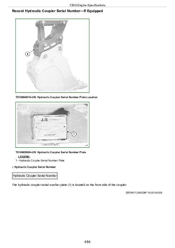
Record Hydraulic Coupler Serial Number—If Equipped
Record Hydraulic Pump Serial Number
Keep Proof of Ownership
Keep Machines Secure
Section 4-6: Miscellaneous—Specifications
135G Engine Specifications
135G Drain and Refill Capacities
135G Machine Specifications
135G Working Ranges
135G Lift Capacity—Rubber Track; Without Blade; Arm: 2.52 m (8 ft. 3 in.); Bucket: 414 kg (913 lb.); Shoe: 500 mm (20 in.)
135G Lift Capacity—Rubber Track; Blade on Ground; Arm: 2.52 m (8 ft. 3 in.); Bucket: 414 kg (913 lb.); Shoe: 500 mm (20 in.)
135G Lift Capacity—Without Blade; Arm: 2.52 m (8 ft. 3 in.); Bucket: 414 kg (913 lb.); Shoe: 600 mm (24 in.)
135G Lift Capacity—Blade on Ground; Arm: 2.52 m (8 ft. 3 in.); Bucket: 414 kg (913 lb.); Shoe: 600 mm (24 in.)
135G Lift Capacity—Without Blade; Arm: 2.52 m (8 ft.3 in.); Bucket: 414 kg (913 lb.); Shoe: 700 mm (28 in.)
135G Lift Capacity—Blade on Ground; Arm: 2.52 m (8 ft. 3 in.); Bucket: 414 kg (913 lb.); Shoe: 700 mm (28 in.)
135G Lift Capacity—Rubber Track; Without Blade; Arm: 3.01 m (9 ft. 11 in.); Bucket: 414 kg (913 lb.); Shoe: 500 mm (20 in.)
135G Lift Capacity—Rubber Track; Blade on Ground; Arm: 3.01 m (9 ft. 11 in.); Bucket: 414 kg (913 lb.); Shoe: 500 mm (20 in.)
135G Lift Capacity—Without Blade; Arm: 3.01 m (9 ft. 11 in.); Bucket: 414 kg (913 lb.); Shoe: 600 mm (24 in.)
135G Lift Capacity—Blade on Ground; Arm: 3.01 m (9 ft. 11 in.); Bucket: 414 kg (913 lb.); Shoe: 600 mm (24 in.)
135G Lift Capacity—Without Blade; Arm: 3.01 m (9 ft. 11 in.); Bucket: 414 kg (913 lb.); Shoe: 700 mm (28 in.)
135G Lift Capacity—Blade on Ground; Arm: 3.01 m (9 ft. 11 in.); Bucket: 414 kg (913 lb.); Shoe: 700 mm (28 in.)
John Deere 135G Excavator Operator's Manual (OMT319586)


