John Deere PowerTech 10.5 L and 12.5 L Diesel Engines Level 6 Electronic Fuel Systems With Lucas EUIs Component Technical Manual (CTM188)
Catalog:
Model:
Complete Technical Manual for John Deere PowerTech 10.5 L and 12.5 L Diesel Engines Level 6 Electronic Fuel Systems With Lucas EUIs, with all the workshop information to maintain, diagnose, repair, and rebuild like professional mechanics.
John Deere PowerTech 10.5 L and 12.5 L Diesel Engines Level 6 Electronic Fuel Systems With Lucas EUIs - (Worldwide Edition) workshop Component Technical Manual includes:
* Numbered table of contents easy to use so that you can find the information you need fast.
* Detailed sub-steps expand on repair procedure information
* Numbered instructions guide you through every repair procedure step by step.
* Troubleshooting and electrical service procedures are combined with detailed wiring diagrams for ease of use.
* Notes, cautions and warnings throughout each chapter pinpoint critical information.
* Bold figure number help you quickly match illustrations with instructions.
* Detailed illustrations, drawings and photos guide you through every procedure.
* Enlarged inset helps you identify and examine parts in detail.
ctm188 - John Deere PowerTech 10.5 L and 12.5 L Diesel Engines Level 6 Electronic Fuel Systems With Lucas EUIs - (Worldwide Edition) Component Technical Manual.pdf
ctm189 - John Deere Motores diésel PowerTech™ de 10.5 l y 12.5 l con sistemas electrónicos de combustible Nivel 6 y con unidad bomba-inyector electrónica (EUI) Lucas -: (Edición mundial).pdf
ctm190 - John Deere Moteurs diesel PowerTech™ 10,5 l et 12,5 l Circuit d'alimentation électronique niveau 6 avec injecteurs-pompes électroniques Lucas -: (Édition mondiale).pdf
ctm191 - John Deere PowerTech™ 10,5-l- und 12,5-l-Dieselmotoren Elektronische Kraftstoffsysteme der Stufe 6 mit Lucas-Pumpe-Düse-Einheiten -: (Weltweite Ausgabe).pdf
ctm192 - John Deere Motori diesel PowerTech™ da 10,5 e 12,5 l Impianti di alimentazione elettronici Livello 6 con iniettori elettronici Lucas -: (Edizione universale).pdf
ctm199 - John Deere Дизельные двигатели PowerTech™ объемом 10,5 л и 12,5 л Электронные топливные системы уровня 6 с электронными насос-форсунками (EUI) Lucas -: (Исполнение для всех стран).pdf
PRODUCT DETAILS:
Total Pages: 864 pages
File Format: PDF (Internal Links, Bookmarked, Table of Contents, Searchable, Printable, high quality)
Category: Component Technical Manual - CTM
Language: English Spanish French German Italian Russian
Published on 2018/04/07
Table of Contents
Foreword
Trademarks
Section 01: General Information
Group 000: Safety
Avoid Heating Near Pressurized Fluid Lines
Avoid High-Pressure Fluids
Avoid Hot Exhaust
Construct Dealer-Made Tools Safely
Decommissioning — Proper Recycling and Disposal of Fluids and Components
Follow Safety Instructions
Handle Agricultural Chemicals Safely
Handle Fluids Safely—Avoid Fires
Handling Batteries Safely
Illuminate Work Area Safely
Install All Guards
Live With Safety
Park Machine Safely
Practice Safe Maintenance
Precautions for Welding
Prepare for Emergencies
Prevent Acid Burns
Prevent Battery Explosions
Prevent Machine Runaway
Protect Against High Pressure Spray
Protect Against Noise
Recognize Safety Information
Remove Paint Before Welding or Heating
Replace Safety Signs
Service Cooling System Safely
Service Machines Safely
Stay Clear of Rotating Drivelines
Support Machine Properly
Understand Signal Words
Use Proper Lifting Equipment
Use Proper Tools
Use Steps and Handholds Correctly
Wait Before Opening High-Pressure Fuel System
Wear Protective Clothing
Work in Clean Area
Work In Ventilated Area
Group 001: Engine Identification
Engine Model Designation
Engine Serial Number Plate Information
Engine Option Code Label
Engine Application Chart
Distinguishing ECUs
Group 002: Fuels
Lubricants and Coolant
Diesel Fuel - Tier 1
Diesel Fuel - Tier 2
Diesel Fuel Additive Products
Bio-Diesel Fuel
Lubricity of Diesel Fuel
Testing Diesel Fuel
Section 02: Repair and Adjustments
Group 090: Dual Rail Fuel System Repair and Adjustment
Dual Rail Fuel System Components (Earlier Engines)
Replace Final (Secondary) Fuel Filter Element
Replacing Primary Fuel Filter/Water Separator
Remove and Install Air Purge Valve
Remove and Install Primary Fuel Filter Check Valve
Remove and Install Fuel System Surge Tank (6125ADW01/70 Engines)
Remove and Install Dual Rail Fuel Supply Pump
Remove and Install Dual Rail Fuel Manifold
Inspect Fuel Pressure Regulating Valve and Return Check Valve
Remove and Install Electronic Unit Injectors
Adjust Electronic Unit Injector Preload
Replace Electronic Unit Injector O-Rings
Replace Electronic Unit Injector Thrust Sleeve, Pad and O-Ring
Flush Fuel Rails
Bleed Fuel System
Group 091: Single Rail Fuel System Repair and Adjustment
General Information
Single Rail Fuel System Components (Later Engines)
Fuel Filter/Water Separator Assembly
Replacing Fuel Filter/Water Separator
Remove and Install Low Pressure Regulating Valve
Remove and Install High Pressure Regulating Valve
Remove and Install 100 Micron Internal Filter Housing Screen Insert
Remove and Install Fuel Filter Check Valve
Remove and Install Primer Pump
Remove and Install Single Rail Fuel Supply Pump
Remove and Install Electronic Unit Injectors (Single Rail Fuel System)
Adjust Electronic Unit Injector Preload
Replace Electronic Unit Injector O-Rings
Replace Electronic Unit Injector Thrust Sleeve, Pad and O-Ring
Bleed Fuel System
Group 110: Electrical Engine Control Repair and Adjustment
John Deere Electronic Control System
Remove and Install Coolant Temperature Sensor
Remove and Install Fuel Temperature Sensor (Dual Rail System)
Remove and Install Fuel Temperature Sensor
Remove and Install Fuel Pressure Sensor
Remove and Install Water-in-Fuel Sensor
Remove and Install Oil Pressure Sensor
Remove and Install Manifold Air Temperature (MAT) Sensor
Remove and Install Manifold Absolute Pressure (MAP) Sensor
Remove and Install Camshaft Position Sensor
Remove and Install Crankshaft Position Sensor
Connectors
Use Electrical Insulating Compound
Using High-Pressure Washer
Connector Repair
Remove Blade Terminals from Connector Body
Repair (Pull Type) METRI-PACK Connectors
Repair (Push Type) METRI-PACK Connectors
Repair DEUTSCH Connectors
Repair CINCH Connectors
Section 03: Theory of Operation
Group 130: Electronic Fuel System Operation
About This Group
Low Pressure Dual Rail Fuel Supply System Operation
Electronic Unit Injector (EUI) Operation on the Dual Rail Fuel System
Low Pressure Single Rail Fuel Supply System Operation
Electronic Unit Injector (EUI) Operation on the Single Rail Fuel System
Group 140: Electrical Control System Operation
Electronic Control System Terminology
Electronic Control System Overview
Electronic Control System Operation
Pilot Injection Operation
Monitoring Engine Parameters
Measuring Temperature
Measuring Pressure
Water In Fuel Sensor
Measuring Throttle Position
Determining Engine Speed and Piston Position
Engine Control Unit (ECU)
Controller Area Network (CAN)
Cruise Control Operation
Engine Protection
Different Derate Programs
Multiple Torque Curve Selection
Governor Droop Mode Selection
Engine Control Unit (ECU) Self-Diagnosis
Section 04: Diagnostics
Group 150: Observable Diagnostics and Tests
About this Group of the Manual
E1 - Engine Cranks/Won't Start
E2 - Engine Misfires/Runs Irregularly
E3 - Engine Does Not Develop Full Power
E4 - Engine Emits Excessive White Exhaust Smoke
E5 - Engine Emits Excessive Black or Gray Exhaust Smoke
E6 - Engine Will Not Crank
E7 - Engine Idles Poorly
E8 - Abnormal Engine Noise
F1 - Dual Rail Fuel Supply System Check
F1 - Dual Rail Fuel Supply System Check
F2 - Excessive Fuel Consumption on a Dual Rail Fuel System
F3 - Fuel in Oil on a Dual Rail Fuel System
F4 - Single Rail Fuel Supply System Check
F4 - Single Rail Fuel Supply System Check
F5 - Excessive Fuel Consumption on Single Rail Fuel System
F6 - Fuel in Oil on Single Rail Fuel System
F7 - Excessive Fuel Filter Replacement
D1 - ECU Does Not Communicate with Service ADVISOR
D2 - ECU Does Not Communicate with Diagnostic Gauge or Gauge Displays CAN Bus Error
D2 - ECU Does Not Communicate with Diagnostic Gauge (Earlier Model)
D2 - ECU Does Not Communicate with Diagnostic Gauge (Earlier Model)
D3 - ECU Does Not Program With Service ADVISOR
D3 - ECU Does Not Communicate with Diagnostic Gauge (Later Model)
D3 - ECU Does Not Communicate with Diagnostic Gauge (Later Model)
Check Dual Rail Fuel Supply Pressure
Bleed Dual Rail Fuel System
Check Single Rail Fuel Supply Pressure
Bleed Single Rail Fuel System
Restarting Engine That Has Run Out Of Fuel (Single Rail Fuel System)
Load Profile Information Test — Instructions
Load Profile Information Test — Instructions (Service ADVISOR 5)
Group 160: Trouble Code Diagnostics and Tests
About This Group of the Manual
Electrical Concepts
Electrical Circuit Malfunctions
Troubleshooting Circuit Malfunctions
Using a Digital Multimeter
Connecting to Diagnostic Scan Tool (DST)
Connecting to Service ADVISOR
Viewing Active DTCs on Diagnostic Gauge (Earlier Model)
Viewing Stored DTCs on Diagnostic Gauge (Earlier Model)
Clearing Stored DTCs on Diagnostic Gauge (Earlier Model)
Engine Configuration Parameters on Diagnostic Gauge (Earlier Model)
Viewing Active DTCs on Diagnostic Gauge (Later Model)
Viewing Stored DTCs on Diagnostic Gauge (Later Model)
Clearing Stored DTCs on Diagnostic Gauge (Later Model)
Data Parameter Description
Engine Test Instructions—Cylinder Misfire Test
Engine Test Instructions—Compression Test
Cylinder Cutout Test Instructions
Cylinder Cutout Test Using JDG1250
Engine Control Unit (ECU) — Donating this Engine’s ECU to be Used Elsewhere
Engine Control Unit (ECU) — Replacing Current ECU with Another ECU
Engine Control Unit (ECU) — Replacing Current ECU with Another ECU — Cannot Communicate with Current ECU
Engine Control Unit (ECU) — Reprogramming Current ECU
Engine Control Unit (ECU) — Reprogramming Instructions
Downloading Payload File For DST
Reprogramming Engine Control Unit (ECU) With DST
Diagnostic Trouble Codes (DTCs)
Listing of Diagnostic Trouble Codes (DTCs) on ECU
Diagnostic Procedure
Intermittent Fault Diagnostics
Terminal Test
T1 - Multi-state Throttle Input High
T1 - Multi-state Throttle Input High
T2 - Multi-state Throttle Input Low
T2 - Multi-state Throttle Input Low
T3 - Analog Throttle (A) Input High
T3 - Analog Throttle (A) Input High
T4 - Analog Throttle (A) Input Low
T4 - Analog Throttle (A) Input Low
T5 - Analog Throttle (B) Input High
T5 - Analog Throttle (B) Input High
T6 - Analog Throttle (B) Input Low
T6 - Analog Throttle (B) Input Low
T7 - CAN Throttle Invalid
T7 - CAN Throttle Invalid
T8 - PWM Throttle Input High
T8 - PWM Throttle Input High
T9 - PWM Throttle Input Low
T9 - PWM Throttle Input Low
T10 - PWM Throttle Abnormal Pulse Width
T10 - PWM Throttle Abnormal Pulse Width
T11 - Excavator Throttle Reference Voltage High
T11 - Excavator Throttle Reference Voltage High
T12 - Excavator Throttle Reference Voltage Low
T12 - Excavator Throttle Reference Voltage Low
T13 - Excavator Throttle Ground Voltage High
T13 - Excavator Throttle Ground Voltage High
T14 - Excavator Throttle Ground Voltage Low
T14 - Excavator Throttle Ground Voltage Low
T15 - Excavator Throttle Input Voltage High
T15 - Excavator Throttle Input Voltage High
T16 - Excavator Throttle Input Voltage Low
T16 - Excavator Throttle Input Voltage Low
T22 - Analog Throttle (A) Input Voltage Out of Range
000028.03 - Throttle Voltage High
000028.04 - Throttle Voltage Low
000029.03 - Throttle Voltage High
000029.04 - Throttle Voltage Low
000091.03 - Throttle Voltage High
000091.04 - Throttle Voltage Low
000091.08 - PWM Throttle Abnormal Pulse Width
000091.09 - Throttle Invalid
000091.14 - Throttle Voltage Out of Range
000094.01 — Fuel Supply Pressure Extremely Low
000094.01 - Fuel Supply Pressure Extremely Low
000094.03 — Fuel Supply Pressure Input Voltage High
000094.03 - Fuel Supply Pressure Input Voltage High
000094.04 — Fuel Supply Pressure Input Voltage Low
000094.04 - Fuel Supply Pressure Input Voltage Low
000094.16 — Fuel Supply Pressure Moderately High
000094.16 - Fuel Supply Pressure Moderately High
000094.18 — Fuel Supply Pressure Moderately Low
000094.18 - Fuel Supply Pressure Moderately Low
000097.00 — Water in Fuel Continuously Detected
000097.00 - Water in Fuel Continuously Detected
000097.03 — Water in Fuel Signal Voltage High
000097.03 - Water in Fuel Signal Voltage High
000097.04 — Water in Fuel Signal Voltage Low
000097.04 - Water in Fuel Signal Voltage Low
000097.16 — Water in Fuel Detected
000097.16 - Water in Fuel Detected
000097.31 — Water in Fuel Detected
000097.31 - Water in Fuel Detected
000100.01 — Engine Oil Pressure Extremely Low
000100.01 - Engine Oil Pressure Extremely Low
000100.03 — Engine Oil Pressure Input Voltage High
000100.03 - Engine Oil Pressure Input Voltage High
000100.04 — Engine Oil Pressure Input Voltage Low
000100.04 - Engine Oil Pressure Input Voltage Low
000100.18 — Engine Oil Pressure Moderately Low
000100.18 - Engine Oil Pressure Moderately Low
000102.03 — Manifold Air Pressure Input Voltage High
000102.03 - Manifold Air Pressure Input Voltage High
000102.04 — Manifold Air Pressure Input Voltage Low
000102.04 - Manifold Air Pressure Input Voltage Low
000105.03 — Manifold Air Temperature Input Voltage High
000105.03 - Manifold Air Temperature Input Voltage High
000105.04 — Manifold Air Temperature Input Voltage Low
000105.04 - Manifold Air Temperature Input Voltage Low
000105.16 — Manifold Air Temperature Moderately High
000105.16 - Manifold Air Temperature Moderately High
000107.00 — Air Filter Restriction High
000107.00 - Air Filter Restriction High
000107.31 — Air Filter Restriction High
000107.31 - Air Filter Restriction High
000110.00 — Engine Coolant Temperature High Most Severe
000110.00 - Engine Coolant Temperature High Most Severe
000110.03 — Engine Coolant Temperature Input Voltage High
000110.03 - Engine Coolant Temperature Input Voltage High
000110.04 — Engine Coolant Temperature Input Voltage Low
000110.04 - Engine Coolant Temperature Input Voltage Low
000110.15 — Engine Coolant Temperature High Least Severe
000110.15 - Engine Coolant Temperature High Least Severe
000110.16 Engine Coolant Temperature High Moderately Severe
000110.16 - Engine Coolant Temperature High Moderately Severe
000111.01 — Engine Coolant Level Low
000111.01 - Engine Coolant Level Low
000158.17 — ECU Power Down Error
000158.17 - ECU Power Down Error
000174.03 — Fuel Temperature Input Voltage High
000174.03 - Fuel Temperature Input Voltage High
000174.04 — Fuel Temperature Input Voltage Low
000174.04 - Fuel Temperature Input Voltage Low
000177.09 - Transmission Oil Temperature Invalid
000190.00 - Engine Speed Extremely High
000190.01 - Engine Extremely Overloaded
000190.16 - Engine Speed Moderately High
000190.18 - Engine Moderately Overloaded
000523.09 - Gear Selection Invalid
000611.03 — Injector Wiring Shorted To Power Source
000611.03 - Injector Wiring Shorted To Power Source
000611.04 — Injector Wiring Shorted To Ground
000611.04 - Injector Wiring Shorted To Ground
000620.03 — Sensor Supply Voltage High
000620.03 - Sensor Supply Voltage High
000620.04 — Sensor Supply Voltage Low
000620.04 - Sensor Supply Voltage Low
000627.01 — Injector Supply Voltage Problem
000627.01 - Injector Supply Voltage Problem
000629.12 - ECU Error
000629.13 - ECU Error
000636.02 — Cam Position Input Noise
000636.02 - Cam Position Input Noise
000636.08 — Cam Position Input Missing
000636.08 - Cam Position Input Missing
000636.10 — Cam Position Input Pattern Error
000636.10 - Cam Position Input Pattern Error
000637.02 — Crank Position Input Noise
000637.02 - Crank Position Input Noise
000637.07 — Crank Position/Cam Position Out of Sync
000637.07 - Crank Position/Cam Position Out of Sync
000637.08 — Crank Position Input Missing
000637.08 - Crank Position Input Missing
000637.10 — Crank Position Input Pattern Error
000637.10 - Crank Position Input Pattern Error
000639.13 — CAN Error
000639.13 - CAN Error
000651.05 — Cylinder #1 EUI Circuit Open
000651.05 - Cylinder #1 EUI Circuit Open
000651.06 — Cylinder #1 EUI Circuit Shorted
000651.06 - Cylinder #1 EUI Circuit Shorted
000652.05 — Cylinder #2 EUI Circuit Open
000652.05 - Cylinder #2 EUI Circuit Open
000652.06 — Cylinder #2 EUI Circuit Shorted
000652.06 - Cylinder #2 EUI Circuit Shorted
000653.05 — Cylinder #3 EUI Circuit Open
000653.05 - Cylinder #3 EUI Circuit Open
000653.06 — Cylinder #3 EUI Circuit Shorted
000653.06 - Cylinder #3 EUI Circuit Shorted
000654.05 — Cylinder #4 EUI Circuit Open
000654.05 - Cylinder #4 EUI Circuit Open
000654.06 — Cylinder #4 EUI Circuit Shorted
000654.06 - Cylinder #4 EUI Circuit Shorted
000655.05 — Cylinder #5 EUI Circuit Open
000655.05 - Cylinder #5 EUI Circuit Open
000655.06 — Cylinder #5 EUI Circuit Shorted
000655.06 - Cylinder #5 EUI Circuit Shorted
000656.05 — Cylinder #6 EUI Circuit Open
000656.05 - Cylinder #6 EUI Circuit Open
000656.06 — Cylinder #6 EUI Circuit Shorted
000656.06 - Cylinder #6 EUI Circuit Shorted
000970.02 — Auxiliary Engine Shutdown Switch Signal Invalid
000970.02 - Auxiliary Engine Shutdown Switch Signal Invalid
000970.31 - Auxiliary Engine Shutdown Switch Active
000971.31 - External Fuel Derate Switch Active
001109.31 - Engine Shutdown Warning
001110.31 - Engine Shutdown
001569.31 - Fuel Derate
002000.13 - Security Violation
Section 05: Tools
Group 170: Repair Tools
JDG145
JDG155
JDG359
JDG364
JDG707
JDG776
JDG777
JDG783
JDG820
JDG865
JDG971
JDG998
JDG1334
JDG10466
JDG11263
JT03513C
JT05412
JT07306
JT07328
JT07195B
Other Material
Electronic Control System Other Material
Group 180: Diagnostic Service Tools
Electronic Control System Diagnostic Tools
Section 06: Specifications
Group 200: Repair Specifications
Unified Inch Bolt and Screw Torque Values
Metric Bolt and Screw Torque Values
General OEM Engine Specifications
Dual Rail Fuel System Specifications
Single Rail Fuel System Specifications
Electronic Engine Control System Specifications
Group 210: Diagnostic Specifications
Fuel System Diagnostic Specifications
Application Specifications
Combines - Sensor Specifications
Combines - Torque Curve Selection
Combines - Governor Mode Selection
Combines - ECU Terminal Identification
Excavators - Sensor Specifications
Excavators - Torque Curve Selection
Excavators - Governor Mode Selection
Excavators - ECU Terminal Identification
Forage Harvesters - Sensor Specifications
Forage Harvesters - Torque Curve Selection
Forage Harvesters - Governor Mode Selection
Forage Harvesters - ECU Terminal Identification
Loaders - Sensor Specifications
Loaders - Torque Curve Selection
Loaders - Governor Mode Selection
Loaders - ECU Terminal Identification
Marine Engines - Sensor Specifications
Marine Engines - Torque Curve Selection
Marine Engines - Governor Mode Selection
Marine Engines - ECU Terminal Identification
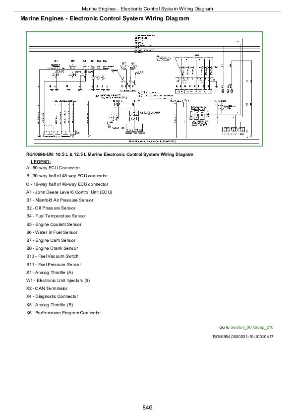
Marine Engines - Electronic Control System Wiring Diagram
12.5 L Marine Application Wheel House Panel Electrical Wiring Diagram
12.5 L Marine Application Fly Bridge Panel Electrical Wiring Diagram
OEM Engines - Sensor Specifications
OEM Engines - Torque Curve Selection
OEM Engines - Governor Mode Selection
OEM Engines - ECU Terminal Identification
OEM Engines - Electronic Control System Wiring Diagram
OEM Engines - Instrument Panel/Engine Start Components Electrical Wiring Diagram
Tractors - Sensor Specifications
Tractors - Torque Curve Selection
Tractors - Governor Mode Selection
Tractors - ECU Terminal Identification
John Deere PowerTech 10.5 L and 12.5 L Diesel Engines Level 6 Electronic Fuel Systems With Lucas EUIs Component Technical Manual (CTM188)


