Jonh Deere 640H and 648H Skidder Repair Service Manual (TM11811)
Catalog:
Model:
Complete Repair Service Technical Manual for Jonh Deere 640H and 648H Skidder (S.N.630436— ), with all the workshop information to maintain, repair, and rebuild like professional mechanics.
Jonh Deere 640H and 648H Skidder (S.N.630436— ) workshop technical manual (repair) includes:
* Numbered table of contents easy to use so that you can find the information you need fast.
* Detailed sub-steps expand on repair procedure information
* Numbered instructions guide you through every repair procedure step by step.
* Notes, cautions and warnings throughout each chapter pinpoint critical information.
* Bold figure number help you quickly match illustrations with instructions.
* Detailed illustrations, drawings and photos guide you through every procedure.
* Enlarged inset helps you identify and examine parts in detail.
tm11811 - Jonh Deere 640H and 648H Skidder (S.N.630436— ) Technical Manual (Repair).pdf
tm11817 - Jonh Deere Débardeurs 640H et 648H (630436— ).pdf
tm12071 - Jonh Deere трелевочных тракторов 640H и 648H (630436— ).pdf
tm11822 - Jonh Deere Remolcadores de troncos 640H y 648H (630436— ).pdf
PRODUCT DETAILS:
Total Pages: 852 pages
File Format: PDF (bookmarked, ToC, Searchable, Printable, high quality)
Category: Repair
Language: English Spanish French Russian
Published on 2018/09/13
TABLE OF CONTENTS
Foreword
Technical Information Feedback Form
Section 00: General Information
Group 0001: Safety
Recognize Safety Information
Follow Safety Instructions
Operate Only If Qualified
Wear Protective Equipment
Avoid Unauthorized Machine Modifications
Inspect Machine
Stay Clear of Moving Parts
Avoid High-Pressure Fluids
Avoid High-Pressure Oils
Do Not Use Starting Fluid
Work In Ventilated Area
Prevent Fires
Prevent Battery Explosions
Handle Chemical Products Safely
Decommissioning — Proper Recycling and Disposal of Fluids and Components
Prepare for Emergencies
Clean Debris from Machine
Use Steps and Handholds Correctly
Start Only From Operator's Seat
Use and Maintain Seat Belt
Prevent Unintended Machine Movement
Avoid Work Site Hazards
Operate Machine Safely
Keep Riders Off Machine
Avoid Backover Accidents
Avoid Machine Tip Over
Operating on Slopes
Operating or Traveling On Public Roads
Inspect and Maintain ROPS
Keep the Operator Protective Structure (OPS) in Place
Add and Operate Attachments Safely
Park and Prepare for Service Safely
Service Tires Safely
Service Cooling System Safely
Service Accumulator Systems Safely
Remove Paint Before Welding or Heating
Make Welding Repairs Safely
Drive Metal Pins Safely
Group 0003: Torque Values
Hardware Torque Specifications
Keeping ROPS Installed Properly
Metric Bolt and Cap Screw Torque Values
Additional Metric Cap Screw Torque Values
Unified Inch Bolt and Cap Screw Torque Values
Check Oil Lines And Fittings
Service Recommendations for 37° Flare and 30° Cone Seat Connectors
Service Recommendations for O-Ring Boss Fittings
Service Recommendations For Flat Face O-Ring Seal Fittings
Service Recommendations for Metric Series Four Bolt Flange Fitting
Service Recommendations For Inch Series Four Bolt Flange Fittings
Section 01: Wheels
Group 0110: Powered Wheels and Fastenings
Wheel Remove and Install
Tire Remove and Install
Dual Wheel Installation
Section 02: Axles and Suspension Systems
Group 0200: Removal and Installation
TeamMate™ IV Axles
Front Axle, Differential, and Oscillation Supports Remove and Install
Rear Axle and Differential Remove and Install
Front Axle Guards Remove and Install
Oscillation Supports Repair
Group 0225: Input Drive Shafts and U-Joints
Front Axle Drive Shaft Remove and Install
Rear Axle and Transmission Drive Shaft Remove and Install
Group 0260: Hydraulic System
Differential Lock Solenoid Valve Repair
Section 03: Transmission
Group 0300: Removal and Installation
Transmission Remove and Install—Direct Drive
Transmission Remove and Install—Torque Converter
Transmission Mount Remove and Install
Group 0315: Controls
Transmission Bump Shifter Remove and Install
Group 0325: Input Drive Shafts and U-Joints
Engine-to-Transmission Drive Shaft Remove and Install—Direct Drive
Engine-to-Transmission Drive Shaft Remove and Install—Torque Converter
Group 0350: Gears, Shafts and Power Shift Clutches
Transmission Repair Procedures
Winch Drive Repair
Input Yoke Remove and Install
Group 0360: Hydraulic System
Transmission Charge Pump Remove and Install—Direct Drive
Transmission Charge Pump Remove and Install
Transmission Charge Pump Drive Repair—Direct Drive
Transmission Suction Tube Repair
Transmission Control Valve Repair—Direct Drive
Transmission Control Valve Repair—Torque Converter
Section 04: Engine
Group 0400: Removal and Installation
PowerTech Plus™ 6.8L (6068) John Deere Engine—6.8L Tier 3/Stage IIIA
PowerTech Plus™ 6.8L (6068) John Deere Engine—6.8L Stage II
Engine Remove and Install—Torque Converter
Engine Remove and Install—Direct Drive
Section 05: Engine Auxiliary Systems
Group 0505: Cold Weather Starting Aids
Do Not Use Ether Start Aid
Group 0510: Cooling Systems
Air Baffle Enclosure Remove and Install
Serpentine Belt Remove and Install
Serpentine Belt Tensioner—Spring Tension Check
Serpentine Belt Tensioner Remove and Install
Aftercooler Remove and Install—Torque Converter
Aftercooler Remove and Install—Direct Drive
Radiator Remove and Install—Torque Converter
Radiator Remove and Install—Direct Drive
Transmission Oil Cooler Remove and Install—Torque Converter
Transmission Oil Cooler Remove and Install—Direct Drive
Hydraulic Oil Cooler Remove and Install—Torque Converter
Hydraulic Oil Cooler Remove and Install—Direct Drive
Fan Blade Remove and Install
Fan Shroud Remove and Install
Group 0520: Intake System
Air Cleaner Remove and Install
Group 0530: Exhaust System
Muffler Remove and Install
Group 0560: External Fuel Supply System
Fuel Tank Remove and Install—Cable Skidder
Fuel Tank Remove and Install—Grapple Skidder
Section 06: Torque Converter
Group 0600: Removal and Installation
Lock Up Torque Converter Housing Remove and Install
Group 0641: Torque Converter Housing
Torque Converter and Torque Converter Housing Disassemble and Assemble
Section 07: Dampener Drive
Group 0752: Elements
Dampener Remove and Install
Transmission Cold Weather Disconnect Linkage Remove and Install—If Equipped
Transmission Cold Weather Disconnect Repair—If Equipped
Section 09: Steering Systems
Group 0930: Secondary Steering
Secondary Steering Pump Remove and Install
Group 0960: Hydraulic System
Steering Valve Remove and Install
Steering Valve Disassemble and Assemble
Steering Cylinder Remove and Install
Group 0962: Dual Mode Steering
Dual Mode Steering Solenoid Valve Remove and Install
Section 10: Service Brakes
Group 1015: Control Linkage
Service Brake Pedal Remove and Install
Group 1060: Hydraulic System
Service Brake Valve Remove and Install
Service Brake Valve Disassemble and Assemble
Service Brake Accumulator Remove and Install
Section 11: Park Brake
Group 1111: Active Elements
Park Brake Remove and Install
Group 1160: Hydraulic System
Park Brake Solenoid Valve Repair
Section 17: Frame, Chassis, or Supporting Structures
Group 1740: Frame Installation
Welding Repair of Major Structure
Engine and Equipment Frames—Separate
Lower Pivot Pin Repair
Upper Pivot Pin Repair
Group 1746: Frame Bottom Guards
Engine Frame Bottom Guard Remove and Install
Equipment Frame Bottom Guard Remove and Install
Section 18: Operator's Station
Group 1800: Removal and Installation
Cab Remove and Install
Cab Isolators Remove and Install
Steering Column and Steering Wheel Remove and Install
Steering Column and Steering Wheel Disassemble and Assemble
Cab Tilt Hand Pump Remove and Install
Cab Tilt Hand Pump Disassemble and Assemble
Cab Tilt Hand Pump Bleeding Procedure
Cab Tilt Cylinder Remove and Install
Group 1810: Operator Enclosure
Window Remove and Install
Window Cleaning Procedure
Cab Door Remove and Install
Cab Door and Door Latch Disassemble and Assemble
Front Windshield Wiper Remove and Install
Rear Windshield Wiper Remove and Install
Windshield Wiper Adjustment
Group 1821: Seat and Seat Belt
Seat Remove and Install
Seat Disassemble and Assemble
Seat Belt Remove and Install
Group 1830: Heating and Air Conditioning
R134a Refrigerant Cautions and Proper Handling
Air Conditioning System Flush and Purge
R134a Refrigerant Oil Information
R134a Refrigerant Recovery/Recycling and Charging Station Installation Procedure
R134a Refrigerant Recovery
R134a System Evacuate
R134a System Charge
Compressor Relief Valve Remove and Install
Air Conditioner Compressor Remove and Install
Air Conditioner Compressor Clutch Remove and Install
Air Conditioner Compressor Manifold Remove and Install
Air Conditioner Condenser Remove and Install
Blower Motor Remove and Install
Precleaner Blower Assembly Remove and Install
Refrigerant High/Low Pressure Switch Remove and Install
Coolant Valve Remove and Install
Freeze Control Switch Remove and Install
Expansion Valve Remove and Install
Heater Core Remove and Install
Evaporator Remove and Install
Receiver-Dryer Remove and Install
Section 19: Sheet Metal and Styling
Group 1910: Hood or Engine Enclosure
Hood Remove and Install
Grille Guard Remove and Install
Grille Housing Remove and Install
Section 20: Safety, Convenience and Miscellaneous
Group 2003: Pressurized Water System
Pressurized Water System—If Equipped
Group 2004: Horn and Warning Devices
Horn Remove and Install
Reverse Warning Alarm Remove and Install
Section 21: Main Hydraulic System
Group 2160: Hydraulic System
General Oil Cleanup Procedure
Hydraulic Component Failure Cleanup Procedure
Hydraulic Pump Remove and Install—Direct Drive
Hydraulic Pump Remove and Install—Torque Converter
Priority Valve Remove and Install
Priority Valve Disassemble and Assemble
Hydraulic Attenuator Remove and Install
Fan Variable Speed and Reversing Manifold Remove and Install
Fan Variable Speed and Reversing Manifold Disassemble and Assemble
Hydraulic Fan Motor Remove and Install
Hydraulic Reservoir Remove and Install
Hydraulic Fan and Cooling Loop Pump Remove and Install—Direct Drive
Hydraulic Fan and Cooling Loop Pump Remove and Install—Torque Converter
Section 30: Winch
Group 3000: Removal and Installation
Winch 4000 Series Remove and Install
Fastening Cable to Winch Drum—4000 Series
Winch Free Spool Drag Adjustment
Winch 6000 Series Remove and Install
Fastening Cable to Winch Drum—6000 Series
Group 3015: Control Linkage
Winch Control Valve Linkage Remove and Install
Winch Control Cable Remove and Install
Group 3025: Input Drive Shafts and U-Joints
Winch Drive Shaft Remove and Install
Winch Drive Shaft Disassemble and Assemble
Group 3050: Drive and Clutch
Winch 4000 Series Drive and Clutch Repair
Winch 6000 Series Drive and Clutch Repair
Section 32: Stacking Blades
Group 3201: Blades
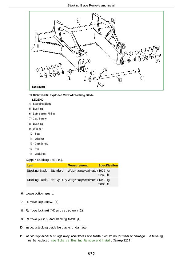
Stacking Blade Remove and Install
Spherical Bushing Remove and Install
Group 3215: Control Linkage
Blade Control Linkage Remove and Install
Blade Control Valve Remove and Install
Group 3260: Hydraulic System
Blade Lift Cylinder Remove and Install
Section 37: Arch or Boom
Group 3740: Frames
Arch Remove and Install
Horizontal Roller Remove and Install
Side Roller Remove and Install
Roller Brackets Remove and Install
Section 38: Grapple
Group 3803: Grapple Mechanism
Grapple Remove and Install
Grapple Disassemble and Assemble
Grapple Dampener Disassemble and Assemble
Grapple Dampener Adjustment
Dampener, Yoke, and Crosshead Pins Lubricate
Grapple Rotate Yoke Disassemble and Assemble
Group 3815: Control Linkage
Single Lever Pilot Controller Remove and Install
Group 3840: Frames
Single Function Grapple Cable Rollers Remove and Install
Dual Function Grapple Cable Rollers Remove and Install
Single Function Grapple Arch Remove and Install
Dual Function Grapple Boom Remove and Install
Dual Function Grapple Arch Remove and Install
Group 3860: Hydraulic System
Arch Cylinder Remove and Install—Single Function Grapple
Boom or Arch Cylinder Remove and Install—Dual Function Grapple
Grapple Tong Cylinder Remove and Install
Grapple Rotate Motor Remove and Install
Grapple Rotate Motor Disassemble
Grapple Rotate Motor Assemble
Rotate Motor Drive Gear Remove and Install
Control Valve Options
Pilot Operated Control Valve Remove and Install
Single Function Pilot Operated Control Valve Disassemble and Assemble
Dual Function Pilot Operated Control Valve Disassemble and Assemble
Control Valve Relief Valves Remove and Install
Lift Check Valve Disassemble and Assemble
Non-adjustable Circuit Relief Valve Disassemble and Assemble
Adjustable Circuit Relief Valve Disassemble and Assemble
Spool Valve Disassemble and Assemble
Detent Disassemble and Assemble
Pilot Operated Valve Remove and Install
Solenoid Operated Valve Remove and Install
Grapple Rotate Solenoid Valve Remove and Install
Grapple Rotate Solenoid Valve Disassemble and Assemble
Flow Divider Repair
Rotary Manifold Remove and Install (S.N. —647783)
Rotary Manifold Remove and Install (S.N. 647784— )
Rotary Manifold Disassemble and Assemble (S.N. —647783)
Rotary Manifold Disassemble and Assemble (S.N. 647784— )
Section 99: Dealer Fabricated Tools
Group 9900: Dealer Fabricated Tools
DFT1099 Bushing Drivers
DFT1216 Converter Housing Support
DFRW20 Compressor Holding Fixture
Jonh Deere 640H and 648H Skidder Repair Service Manual (TM11811)


