John Deere 540H and 548H Skidder ( —630435) Repair Technical Manual (TM11330)
Catalog:
Model:
John Deere 540H and 548H Skidder ( —630435) is divided into different sections. Each section covers a specific component or system with detailed illustrations. A table of contents is placed at the beginning of each section. Pages are easily found by category, and each page is expandable for great detail. The printer-ready PDF documents work like a charm on all kinds of devices. This document is printable, without restrictions, contains searchable text, bookmarks, crosslinks for easy navigation.
TM11330 - John Deere 540H and 548H Skidder ( —630435) Repair Technical Manual.pdf
tm11335 - John Deere Débardeurs 540H et 548H (SN —630435).pdf
tm11396 - John Deere Skidder 540H und 548H ( —630435).pdf
Category: Repair
Language: English French German
Published on 2018/08/24
TABLE OF CONTENTS
Section 00: General Information...12
Group 0001: Safety Information...12
Recognize Safety Information...15
Follow Safety Instructions...16
Operate Only If Qualified...17
Wear Protective Equipment...18
Avoid Unauthorized Machine Modifications...19
Inspect Machine...20
Stay Clear of Moving Parts...21
Avoid High-Pressure Fluids...22
Avoid High-Pressure Oils...23
Do Not Use Starting Fluid...24
Beware of Exhaust Fumes...25
Prevent Fires...26
Clean Debris from Machine...27
Prevent Battery Explosions...28
Handle Chemical Products Safely...29
Dispose of Waste Properly...30
Prepare for Emergencies...31
Use Steps and Handholds Correctly...32
Start Only From Operator's Seat...33
Use and Maintain Seat Belt...34
Prevent Unintended Machine Movement...35
Avoid Work Site Hazards...36
Operate Machine Safely...37
Keep Riders Off Machine...38
Avoid Backover Accidents...39
Avoid Machine Tip Over...40
Operating on Slopes...42
Operating or Traveling On Public Roads...43
Inspect and Maintain ROPS...44
Keep the Operator Protective Structure (OPS) in Place...45
Add and Operate Attachments Safely...46
Park and Prepare for Service Safely...47
Service Tires Safely...49
Service Cooling System Safely...50
Remove Paint Before Welding or Heating...51
Make Welding Repairs Safely...52
Drive Metal Pins Safely...53
Group 0003: Torque Values...13
Hardware Torque Specifications...55
Keeping ROPS Installed Properly...56
Metric Bolt and Cap Screw Torque Values...58
Additional Metric Cap Screw Torque Values...60
Unified Inch Bolt and Cap Screw Torque Values...62
Check Oil Lines And Fittings...64
Service Recommendations for 37° Flare and 30° Cone Seat Connectors...65
Service Recommendations for O-Ring Boss Fittings...67
Service Recommendations For Flat Face O-Ring Seal Fittings...69
Service Recommendations for Metric Series Four Bolt Flange Fitting...71
Service Recommendations For Inch Series Four Bolt Flange Fittings...73
Section 01: Wheels...75
Group 0110: Powered Wheels and Fastenings...75
Wheel Remove and Install...78
Tire Remove and Install...80
Dual Wheel Installation...83
Section 02: Axles and Suspension Systems...84
Group 0200: Removal and Installation...84
TeamMate™ IV 1200 Series Inboard Planetary Axles...86
Front Axle, Differential, and Oscillation Supports Remove and Install...87
Rear Axle and Differential Remove and Install...94
Front Axle Guards Remove and Install...99
Oscillation Supports Repair...100
Group 0225: Input Drive Shafts and U-Joints...84
Front Axle Drive Shaft Remove and Install...103
Rear Axle and Transmission Drive Shaft Remove and Install...105
Group 0260: Hydraulic System...84
Differential Lock Solenoid Valve Repair...112
Section 03: Transmission...115
Group 0300: Removal and Installation...115
Transmission Remove and Install...130
Transmission Mount Remove and Install...144
Group 0315: Controls...115
Transmission Bump Shifter Remove and Install...148
Group 0325: Input Drive Shafts and U-Joints...115
Engine-to-Transmission Drive Shaft Remove and Install...154
Group 0350: Gears, Shafts and Power Shift Clutches...115
Transmission Repair Procedures...159
Winch Drive Repair...160
Input Yoke Remove and Install...167
Group 0360: Hydraulic System...115
Transmission Charge Pump Remove and Install...175
Transmission Charge Pump Drive Repair...181
Transmission Suction Tube Repair...192
Transmission Control Valve Repair...194
Section 04: Engine...206
Group 0400: Removal and Installation...206
PowerTech Plus™ 6.8 L (6068) John Deere Engines...208
Engine Removal...209
Engine Installation...219
Section 05: Engine Auxiliary Systems...223
Group 0505: Cold Weather Starting Aids...223
Do Not Use Ether Start Aid...225
Group 0510: Cooling Systems...223
Fan Guards Remove and Install...227
Belt Remove and Install...228
Belt Tensioner—Spring Tension Check...229
Belt Tensioner Remove and Install...231
Aftercooler Remove and Install...232
Radiator Remove and Install...236
Transmission Cooler Remove and Install...239
Hydraulic Oil Cooler Remove and Install...242
Fan Shroud Remove and Install...245
Group 0520: Intake System...223
Air Cleaner Remove and Install...249
Group 0530: Exhaust System...223
Muffler Remove and Install...252
Group 0560: External Fuel Supply System...223
Fuel Tank Remove and Install...257
Section 07: Dampener Drive...261
Group 0752: Elements...261
Dampener Remove and Install...264
Transmission Cold Weather Disconnect Linkage Remove and Install...266
Transmission Cold Weather Disconnect Repair...270
Section 09: Steering Systems...276
Group 0930: Secondary Steering...276
Secondary Steering Pump Remove and Install...280
Group 0960: Hydraulic System...276
Steering Valve Remove and Install...289
Steering Valve Disassemble and Assemble...295
Steering Cylinder Remove and Install...302
Group 0962: Dual Mode Steering...276
Dual Mode Steering Solenoid Valve Remove and Install...308
Section 10: Service Brakes...311
Group 1015: Control Linkage...311
Service Brake Pedal Remove and Install...313
Group 1060: Hydraulic System...311
Service Brake Valve Remove and Install...318
Service Brake Valve Disassemble and Assemble...322
Service Brake Accumulator Remove and Install...324
Section 11: Park Brake...328
Group 1111: Active Elements...328
Park Brake Remove and Install...333
Group 1160: Hydraulic System...328
Park Brake Solenoid Valve Repair...340
Section 17: Frame, Chassis, or Supporting Structures...343
Group 1740: Frame Installation...343
Welding Repair of Major Structure...346
Engine and Equipment Frames—Separate...348
Lower Pivot Pin Repair...353
Upper Pivot Pin Repair...360
Group 1746: Frame Bottom Guards...343
Engine Frame Bottom Guard Remove and Install...369
Equipment Frame Bottom Guard Remove and Install...371
Section 18: Operator's Station...373
Group 1800: Removal and Installation...373
Cab Remove and Install...393
Cab Isolators Remove and Install...411
Steering Column and Steering Wheel Remove and Install...414
Steering Column and Steering Wheel Disassemble and Assemble...417
Cab Tilt Hand Pump Remove and Install...419
Cab Tilt Hand Pump Disassemble and Assemble...422
Cab Tilt Hand Pump Bleeding Procedure...424
Cab Tilt Cylinder Remove and Install...427
Group 1810: Operator Enclosure...373
Window Remove and Install...434
Window Cleaning Procedure...438
Cab Door Remove and Install...439
Cab Door and Door Latch Disassemble and Assemble...441
Front Windshield Wiper Remove and Install...444
Rear Windshield Wiper Remove and Install...446
Windshield Wiper Adjustment...449
Group 1821: Seat and Seat Belt...373
Seat Remove and Install...453
Seat Disassemble and Assemble...455
Seat Belt Remove and Install...459
Group 1830: Heating and Air Conditioning...373
Refrigerant Cautions and Proper Handling...461
R134a Refrigerant Recovery, Recycling and Charging Station Installation Procedure...462
R134a Refrigerant Oil Information...464
Recover R134a Refrigerant...467
Evacuate R134a System...468
Charge R134a System...470
Air Conditioning Compressor Remove and Install...471
Air Conditioning Condenser Remove and Install...473
Receiver Dryer Remove and Install...475
Expansion Valve Remove and Install...477
Air Conditioner and Heater Remove and Install...479
Section 19: Sheet Metal and Styling...481
Group 1910: Hood or Engine Enclosure...481
Hood Remove and Install...487
Section 20: Safety, Convenience and Miscellaneous...492
Group 2003: Pressurized Water System...496
Pressurized Water System...496
Group 2004: Horn and Warning Devices...492
Horn Remove and Install...500
Reverse Warning Alarm Remove and Install...501
Section 21: Main Hydraulic System...502
Group 2160: Hydraulic System...502
Hydraulic Pump Remove and Install...511
Hydraulic Pump Disassemble and Assemble...519
Priority Valve Repair...534
Cold Start Dump Valve Remove and Install (If Equipped)...537
Fan Variable Speed and Reversing Manifold Remove and Install...539
Fan Variable Speed and Reversing Manifold Disassemble and Assemble...541
Hydraulic Fan Motor Remove and Install...542
Hydraulic Reservoir Remove and Install...546
Hydraulic Fan and Cooling Loop Pump Remove and Install...555
Hydraulic Oil Cleanup Procedure Using Portable Filter Caddy...558
Section 30: Winch...559
Group 3000: Removal and Installation...559
Winch 4000 Series Remove and Install...566
Fastening Cable to Winch Drum—4000 Series...572
Winch Free Spool Drag Adjustment...576
Group 3015: Control Linkage...559
Winch Control Valve Linkage Remove and Install...579
Winch Control Cable Remove and Install...581
Group 3025: Input Drive Shafts and U-Joints...559
Winch Drive Shaft Remove and Install...587
Winch 4000 Series Drive Shaft Disassemble and Assemble...589
Group 3050: Drive and Clutch...559
Winch 4000 Series Drive and Clutch Repair...591
Section 32: Stacking Blades...592
Group 3201: Blades...592
Stacking Blade Remove and Install...598
Spherical Bushing Remove and Install...603
Group 3215: Control Linkage...592
Blade Control Linkage Remove and Install...607
Blade Control Valve Remove and Install...609
Group 3260: Hydraulic System...592
Blade Lift Cylinder Remove and Install...613
Section 37: Arch or Boom...615
Group 3740: Frames...615
Arch Remove and Install...618
Horizontal Roller Remove and Install...620
Side Roller Remove and Install...622
Roller Brackets Remove and Install...625
Section 38: Grapple...626
Group 3803: Grapple Mechanism...626
Grapple Remove and Install...631
Grapple Disassemble and Assemble...634
Grapple Dampener Repair...636
Grapple Dampener Adjustment...639
Dampener, Yoke, and Crosshead Pins Lubricate...642
Grapple Rotate Yoke Repair...644
Group 3815: Control Linkage...626
Single Function Grapple Control Linkage Repair...664
Single Lever Pilot Controller Remove and Install...666
Group 3840: Frames...626
Single Function Grapple Cable Rollers Remove and Install...671
Single Function Grapple Arch Remove and Install...673
Group 3860: Hydraulic System...626
Arch Cylinder Remove and Install—Single Function Grapple...679
Grapple Tong Cylinder Remove and Install...681
Grapple Rotate Motor Remove and Install...684
Grapple Rotate Motor Disassemble...687
Grapple Rotate Motor Assembly...695
Rotate Motor Drive Gear Remove and Install...704
Control Valve Options...705
Pilot Operated Control Valve Remove and Install...707
Mechanical Linkage Control Valve Remove and Install...711
Single Function Mechanical Linkage Control Valve Disassemble and Assemble...714
Single Function Pilot Operated Control Valve Disassemble and Assemble...717
Control Valve Relief Valves Remove and Install...720
Lift Check Valve Disassemble and Assemble...722
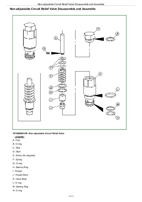
Non-adjustable Circuit Relief Valve Disassemble and Assemble...723
Adjustable Circuit Relief Valve Disassemble and Assemble...725
Spool Valve Disassemble and Assemble...727
Detent Disassemble and Assemble...729
Pilot Operated Valve Remove and Install...731
Solenoid Operated Valve Remove and Install...733
Grapple Rotate Solenoid Valve Remove and Install...735
Grapple Rotate Solenoid Valve Disassemble and Assemble...738
Flow Divider Repair...740
Rotary Manifold Remove and Install...743
Rotary Manifold Disassemble and Assemble...746
Section 99: Dealer Fabricated Tools...751
Group 9900: Dealer Fabricated Tools...751
DFT1099 Bushing Drivers...754
DFT1216 Converter Housing Support...756
DFRW20 Compressor Holding Fixture...758
John Deere 540H and 548H Skidder ( —630435) Repair Technical Manual (TM11330)


