John Deere 848H Skidder (S.N. —630435) Repair Service Manual (TM10289)
Catalog:
Model:
Complete Repair Service Technical Manual for John Deere 848H Skidder (S.N. —630435), with all the workshop information to maintain, repair, and rebuild like professional mechanics.
John Deere 848H Skidder (S.N. —630435) workshop technical manual (repair) includes:
* Numbered table of contents easy to use so that you can find the information you need fast.
* Detailed sub-steps expand on repair procedure information
* Numbered instructions guide you through every repair procedure step by step.
* Notes, cautions and warnings throughout each chapter pinpoint critical information.
* Bold figure number help you quickly match illustrations with instructions.
* Detailed illustrations, drawings and photos guide you through every procedure.
* Enlarged inset helps you identify and examine parts in detail.
TM10289 - John Deere 848H Skidder (S.N. —630435) Repair Technical Manual.pdf
TM11047 - John Deere Débardeurs 848H ( —630435).pdf
Category: Repair
Language: English French
Published on 2018/09/06
PRODUCT DETAILS:
Total Pages: 762 pages
File Format: PDF (bookmarked, ToC, Searchable, Printable)
Language: English
TABLE OF CONTENTS
Section 00: General Information...12
Group 0001: Safety Information...12
Recognize Safety Information...15
Follow Safety Instructions...16
Operate Only If Qualified...17
Wear Protective Equipment...18
Avoid Unauthorized Machine Modifications...19
Inspect Machine...20
Stay Clear of Moving Parts...21
Avoid High-Pressure Oils...22
Avoid High-Pressure Fluids...23
Do Not Use Starting Fluid...24
Beware of Exhaust Fumes...25
Prevent Fires...26
Prevent Battery Explosions...27
Handle Chemical Products Safely...28
Dispose of Waste Properly...29
Prepare for Emergencies...30
Use Steps and Handholds Correctly...31
Start Only From Operator's Seat...32
Use and Maintain Seat Belt...33
Prevent Unintended Machine Movement...34
Avoid Work Site Hazards...35
Operate Machine Safely...36
Keep Riders Off Machine...37
Avoid Backover Accidents...38
Avoid Machine Tip Over...39
Operating on Slopes...41
Operating or Traveling On Public Roads...42
Inspect and Maintain ROPS...43
Keep the Operator Protective Structure (OPS) in Place...44
Add and Operate Attachments Safely...45
Park and Prepare for Service Safely...46
Service Cooling System Safely...48
Remove Paint Before Welding or Heating...49
Make Welding Repairs Safely...50
Drive Metal Pins Safely...51
Group 0003: Torque Values...13
Hardware Torque Specifications...53
Keeping ROPS Installed Properly...54
Metric Bolt and Cap Screw Torque Values...56
Additional Metric Cap Screw Torque Values...58
Unified Inch Bolt and Cap Screw Torque Values...60
Check Oil Lines And Fittings...62
Service Recommendations for 37° Flare and 30° Cone Seat Connectors...63
Service Recommendations for O-Ring Boss Fittings...65
Service Recommendations For Flat Face O-Ring Seal Fittings...67
Service Recommendations for Metric Series Four Bolt Flange Fitting...69
Service Recommendations For Inch Series Four Bolt Flange Fittings...71
Section 01: Wheels...73
Group 110: Powered Wheels and Fastenings...73
Wheel Remove and Install...76
Tire Remove and Install...78
Dual Wheel Installation...81
Section 02: Axle...82
Group 0200: Removal and Installation...82
TeamMate™ IV Axles...84
Front Axle, Differential, and Oscillation Supports Remove and Install...85
Rear Axle and Differential Remove and Install...92
Front Axle Guards Remove and Install...98
Oscillation Supports Repair...99
Group 0225: Input Drive Shafts and U-Joints...82
Front Axle Drive Shaft Remove and Install...102
Rear Axle and Transmission Drive Shaft Remove and Install...104
Group 0260: Hydraulic System...82
Differential Lock Solenoid Valve Repair...111
Section 03: Transmission...114
Group 0300: Removal and Installation...114
Transmission Remove and Install...128
Transmission Mount Remove and Install...141
Group 0315: Controls...114
Transmission Bump Shifter Remove and Install...145
Group 0325: Input Drive Shafts and U-Joints...114
Engine-to-Transmission Drive Shaft Remove and Install...149
Group 0350: Gears, Shafts and Power Shift Clutches...114
Transmission Repair Procedures...152
Winch Drive Repair...153
Input Yoke Remove and Install...160
Group 0360: Hydraulic System...114
Transmission Charge Pump Remove and Install...165
Transmission Suction Tube Repair...168
Transmission Control Valve Repair...170
Section 04: Engine...182
Group 0400: Removal and Installation...182
6068 John Deere Engine POWERTECH POWERTECH is a trademark of Deere & Company 6.8 L Diesel Engines—Base Engine—Use CTM104...182
6068 John Deere Engine POWERTECH POWERTECH is a trademark of Deere & Company 6.8 L—Level 14 Electronic Fuel System With Denso HPCR—Use CTM320 Repairs...182
Engine Removal...186
Engine Installation...197
Section 05: Engine Auxiliary Systems...201
Group 0505: Cold Weather Starting Aids...201
Do Not Use Ether Start Aid...203
Group 0510: Cooling Systems...201
Fan Guards Remove and Install...205
Belt Remove and Install...206
Belt Tensioner—Spring Tension Check...207
Belt Tensioner Remove and Install...209
Aftercooler Remove and Install...210
Radiator Remove and Install...214
Transmission Cooler Remove and Install...218
Hydraulic Oil Cooler Remove and Install...222
Fan Shroud Remove and Install...224
Group 0520: Intake System...201
Air Cleaner Remove and Install...228
Group 0530: Exhaust System...201
Muffler Remove and Install...231
Group 0560: External Fuel Supply...201
Fuel Tank Remove and Install—Grapple Skidder...236
Section 06: Torque Converter...240
Group 0600: Remove and Install...240
Torque Converter Housing Remove and Install...254
Group 0641: Torque Converter Housing...240
Torque Converter and Torque Converter Housing Disassemble and Assemble...268
Section 09: Steering System...269
Group 0930: Secondary Steering...269
Secondary Steering Pump Remove and Install...274
Group 0960: Hydraulic System...269
Steering Valve Remove and Install...284
Steering Valve Disassemble and Assemble...290
Steering Cylinder Remove and Install...297
Group 0962: Dual Mode Steering...269
Dual Mode Steering Solenoid Valve Remove and Install...303
Section 10: Service Brakes...306
Group 1015: Controls Linkage...306
Service Brake Pedal Remove and Install...308
Group 1060: Hydraulic System...306
Service Brake Valve Remove and Install...313
Service Brake Valve Disassemble and Assemble...317
Service Brake Accumulator Remove and Install...319
Section 11: Park Brake...323
Group 1111: Active Elements...323
Park Brake Remove and Install...328
Group 1160: Hydraulic System...323
Park Brake Solenoid Valve Repair...335
Section 17: Frame, Chassis, or Supporting Structures...338
Group 1740: Frame Installation...338
Welding Repair of Major Structure...341
Engine and Equipment Frames—Separate...343
Lower Pivot Pin Repair...348
Upper Pivot Pin Repair...355
Group 1746: Frame Bottom Guards...338
Engine Frame Bottom Guard Remove and Install...364
Equipment Frame Bottom Guard Remove and Install...366
Section 18: Operator's Station...368
Group 1800: Removal and Installation...368
Cab Remove and Install...388
Cab Isolators Remove and Install...406
Steering Column and Steering Wheel Remove and Install...409
Steering Column and Steering Wheel Disassemble and Assemble...412
Cab Tilt Hand Pump Remove and Install...414
Cab Tilt Hand Pump Disassemble and Assemble...417
Cab Tilt Hand Pump Bleeding Procedure...419
Cab Tilt Cylinder Remove and Install...422
Group 1810: Operator Enclosure...368
Window Remove and Install...429
Window Cleaning Procedure...433
Cab Door Remove and Install...434
Cab Door and Door Latch Disassemble and Assemble...436
Front Windshield Wiper Remove and Install...439
Rear Windshield Wiper Remove and Install...441
Windshield Wiper Adjustment...444
Group 1821: Seat and Seat Belt...368
Seat Remove and Install...448
Seat Disassemble and Assemble...450
Seat Belt Remove and Install...454
Group 1830: Heating and Air Conditioning...368
Proper Refrigerant Handling...456
Flush and Purge Air Conditioner System...457
R134a Refrigerant Oil Information...461
R134a Refrigerant Recovery, Recycling and Charging Station Installation Procedure...464
Recover R134a Refrigerant...466
Evacuate R134a System...467
Charge R134a System...469
Compressor Relief Valve Remove and Install...470
Refrigerant High/Low Pressure Switch Remove and Install...471
Air Conditioning Compressor Remove and Install...473
Air Conditioning Compressor Clutch Remove and Install...475
Air Conditioning Compressor Manifold Remove and Install...479
Air Conditioning Condenser Remove and Install...481
Evaporator Remove and Install...483
Expansion Valve Remove and Install...485
Blower Motor Remove and Install...487
Heater Core Remove and Install...489
Coolant Valve Remove and Install...491
Receiver Dryer Remove and Install...493
Freeze Control Switch Remove and Install...495
Section 19: Sheet Metal and Styling...498
Group 1910: Hood or Engine Enclosure...498
Hood Remove and Install...504
Section 20: Safety, Convenience, and Miscellaneous...509
Group 2003: Pressurized Water System...513
Pressurized Water System...513
Group 2004: Horn and Warning Devices...509
Horn Remove and Install...517
Reverse Warning Alarm Remove and Install...518
Section 21: Main Hydraulic System...519
Group 2160: Hydraulic System...519
Hydraulic Pump Remove and Install...525
Hydraulic Pump Disassemble and Assemble...530
Priority Valve Repair...545
Cold Start Dump Valve Remove and Install (If Equipped)...548
Fan Variable Speed and Reversing Manifold Remove and Install...550
Fan Variable Speed and Reversing Manifold Disassemble and Assemble...552
Hydraulic Fan Motor Remove and Install...553
Hydraulic Fan and Cooling Loop Pump Remove and Install...557
Hydraulic Reservoir Remove and Install...560
Hydraulic Oil Cleanup Procedure Using Portable Filter Caddy...569
Section 30: Winch...570
Group 3000: Removal and Installation...570
Winch 4000 Series Remove and Install...577
Fastening Cable to Winch Drum—4000 Series...583
Winch Free Spool Drag Adjustment...587
Winch 6000 Series Remove and Install...589
Fastening Cable to Winch Drum—6000 Series...594
Group 3015: Controls Linkage...570
Winch Control Valve Linkage Remove and Install...598
Winch Control Cable Remove and Install...600
Group 3025: Input Drive Shafts and U-Joints...570
Winch Drive Shaft Remove and Install...607
Winch 4000 Series Drive Shaft Disassemble and Assemble...609
Group 3050: Drive and Clutch...570
Winch 4000 Series Drive and Clutch Repair...611
Winch 6000 Series Drive and Clutch Repair...612
Section 32: Stacking Blades...613
Group 3201: Blades...613
Stacking Blade Remove and Install...619
Spherical Bushing Remove and Install...624
Group 3215: Controls Linkage...613
Blade Control Linkage Remove and Install...628
Blade Control Valve Remove and Install...630
Group 3260: Hydraulic System...613
Blade Lift Cylinder Remove and Install...633
Section 38: Grapple...635
Group 3803: Grapple Mechanism...635
Grapple Remove and Install...640
Grapple Disassemble and Assemble...643
Grapple Damper Repair...645
Grapple Damper Adjustment...648
Dampener, Yoke, and Crosshead Pins Lubricate...651
Grapple Rotate Yoke Repair...653
Group 3815: Controls Linkage...635
Single Lever Pilot Controller Remove and Install...674
Group 3840: Frames...635
Dual Function Grapple Cable Rollers Remove and Install...679
Dual Function Grapple Boom Remove and Install...681
Dual Function Grapple Arch Remove and Install...683
Group 3860: Hydraulic System...635
Boom or Arch Cylinder Remove and Install—Dual Function Grapple...688
Grapple Tong Cylinder Remove and Install...691
Grapple Rotate Motor Remove and Install...694
Grapple Rotate Motor Disassemble...697
Grapple Rotate Motor Assembly...705
Rotate Motor Drive Gear Remove and Install...714
Control Valve Options...715
Pilot Operated Control Valve Remove and Install...716
Dual Function Pilot Operated Control Valve Disassemble and Assemble...720
Control Valve Relief Valves Remove and Install...723
Lift Check Valve Disassemble and Assemble...725
Non-adjustable Circuit Relief Valve Disassemble and Assemble...726
Adjustable Circuit Relief Valve Disassemble and Assemble...728
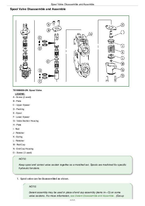
Spool Valve Disassemble and Assemble...730
Detent Disassemble and Assemble...732
Pilot Operated Valve Remove and Install...734
Solenoid Operated Valve Remove and Install...736
Grapple Rotate Solenoid Valve Remove and Install...738
Grapple Rotate Solenoid Valve Disassemble and Assemble...741
Flow Divider Repair...743
Rotary Manifold Remove and Install...746
Rotary Manifold Disassemble and Assemble...749
Section 99: Dealer Fabricated Tools...753
Group 9900: Dealer Fabricated Tools...753
DFT1099 Bushing Drivers...756
DFT1216 Converter Housing Support...758
DFRW20 Compressor Holding Fixture...760
John Deere 848H Skidder (S.N. —630435) Repair Service Manual (TM10289)


