John Deere PowerTech E 2.4L and 3.0L Diesel Engines Component Technical Manual (CTM101019)
Catalog:
Model:
Complete Component Technical Manual with Electrical Wiring Diagrams for John Deere PowerTech E 2.4L and 3.0L Diesel Engines, with all the shop information to maintain, diagnose, repair, and service like professional mechanics.
John Deere PowerTech E 2.4L and 3.0L Diesel Engines component technical service repair manual includes:
* Numbered table of contents easy to use so that you can find the information you need fast.
* Detailed sub-steps expand on repair procedure information
* Numbered instructions guide you through every repair procedure step by step.
* Troubleshooting and electrical service procedures are combined with detailed wiring diagrams for ease of use.
* Notes, cautions and warnings throughout each chapter pinpoint critical information.
* Bold figure number help you quickly match illustrations with instructions.
* Detailed illustrations, drawings and photos guide you through every procedure.
* Enlarged inset helps you identify and examine parts in detail.
ctm101019 - John Deere PowerTech™ E 2.4L and 3.0L Diesel Engines - (Worldwide Edition) Component Technical Manual.pdf
ctm101028 - John Deere Moteurs diesel PowerTech™ E 2,4 l et 3,0 l -: (Édition mondiale).pdf
ctm101029 - John Deere PowerTech™ E 2,4-l- und 3,0-l- Dieselmotoren -: (Weltweite Ausgabe).pdf
ctm101039 - John Deere Motori diesel PowerTech™ E da 2,4 e 3,0 l -: (Edizione universale).pdf
ctm101054 - John Deere Motores Diesel PowerTech™ E 2,4 L e 3,0 L -: (Edição Mundial).pdf
ctm101059 - John Deere Дизельные двигатели PowerTech™ E объемом 2,4 л и 3,0 л -: (Исполнение для всех стран).pdf
ctm101063 - John Deere Motores diésel PowerTech™ E de 2.4 l y 3.0 l -: (Edición mundial).pdf
Total Pages: 1,612 pages
File Format: PDF ( bookmarked, ToC, Searchable, Printable)
Category: CTM - Component Technical Manual
Language: English Spanish French German Italian Portuguese Russian
Published on 2018/04/17
Table of Contents
Foreword
Related Manuals
Training Information
Definition Of Terms
PowerTech™ E 2.4L and 3.0L Diesel Engines
Section 01: General Information
Group 000: Safety
About The Group
Avoid Heating Near Pressurized Fluid Lines
Avoid High-Pressure Fluids
Avoid Hot Exhaust
Avoid Static Electricity Risk When Refueling
Construct Dealer-Made Tools Safely
Dispose of Waste Properly
Follow Safety Instructions
Handle Chemical Products Safely
Handle Fluids Safely—Avoid Fires
Handle Fuel Safely—Avoid Fires
Handle Starting Fluid Safely
Handling Batteries Safely
Illuminate Work Area Safely
Install All Guards
Live With Safety
Prevent Acid Burns
Prevent Battery Explosions
Practice Safe Maintenance
Prepare for Emergencies
Protect Against High Pressure Spray
Protect Against Noise
Recognize Safety Information
Remove Paint Before Welding or Heating
Replace Safety Signs
Service Cooling System Safely
Service Machines Safely
Stay Clear of Rotating Drivelines
Understand Signal Words
Use Proper Lifting Equipment
Use Proper Tools
Wait Before Opening High-Pressure Fuel System
Wear Protective Clothing
Work in Clean Area
Work In Ventilated Area
Group 001: Engine Identification
Engine Model Designation
Engine Serial Number Plate
Record Engine Serial Number
OEM Engine Option Code Label
Information Relative to Emissions Regulations
Emissions Control System Certification Label
Group 002: Fuels, Lubricants, and Coolant
Diesel Fuel
Diesel Fuel Additive Products
Biodiesel Fuel
Handling and Storing Diesel Fuel
Filling Fuel Tank
Lubricity of Diesel Fuel
Testing Diesel Fuel
Diesel Engine Coolant
Supplemental Coolant Additives
Drain Intervals for Diesel Engine Coolant
Diesel Engine Coolant (engine without wet sleeve cylinder liners)
Disposing of Coolant
Operating in Warm Temperature Climates
Testing Diesel Engine Coolant
Additional Information About Diesel Engine Coolants and Supplemental Coolant Additives
Diesel Engine Break-In Oil
Diesel Engine Oil
Extended Diesel Engine Oil Service Intervals
Grease
Lubricant Storage
Mixing of Lubricants
Alternative and Synthetic Lubricants
Minimizing the Effect of Cold Weather on Diesel Engines
OILSCAN OILSCAN is a trademark of Deere & Company. and COOLSCAN COOLSCAN is a trademark of Deere & Company.
Section 02: Repair and Adjustments
Group 010: Engine Rebuild
Engine Stand Safety Precautions
Engine Overhaul Guidelines
Engine Repair Stand
Adapters Installation on Engine Repair Stand
Engine Lifting Procedure
Engine Mounting on Repair Stand
Clean Engine
Disconnect Turbocharger Oil Inlet Line
Engine Disassembly Sequence
Engine Assembly Sequence
Engine Break-In Guidelines
Perform Engine Break-In
Group 020: Cylinder Head and Valves
Cylinder Head Exploded View
Cylinder Head and Valves — Troubleshooting Guide
Cylinder Head — Removal
Cylinder Head — Cleaning and Inspection
Cylinder Head — Flatness Check
Cylinder Head — Thickness Check
Cylinder Head and Gasket — Inspection
Cylinder Head Cap Screw — Inspection
Cylinder Head (4-Cylinder) — Installation
Cylinder Head (5-Cylinder) — Installation
Injector Nozzle Bore — Cleaning and Inspection
Rocker Arm Cover — Removal
Rocker Arm Assembly — Removal
Rocker Arm Assembly — Inspection
Rocker Arm Assembly — Installation
Rocker Arm Cover — Installation
Valve — Adjustment Procedure
Valve — Removal
Valve — Cleaning and Inspection
Valve — Measurement
Valve — Grinding
Valve — Installation
Valve Guide — Cleaning and Inspection
Valve Guide — Measurement
Valve Guide — Knurling
Valve Seat — Cleaning and Inspection
Valve Seat — Recess Measurement
Valve Seat — Grinding
Valve Spring — Cleaning and Inspection
Valve Spring — Measurement
Group 030: Cylinder Block, Pistons, and Rods
Cylinder Block, Piston and Rod — Troubleshooting Guide
Connecting Rods — General Information
Connecting Rod Bearings — Inspection and Measurement (Rods and Crankshaft Removed from Engine)
Connecting Rod Bearings — Inspection and Measurement (Rods and Crankshaft in Engine)
Connecting Rod and Cap — Inspection
Connecting Rod Center-to-Center — Bore Measurement
Connecting Rod Cap Screws — Torque-Turn
Cylinder Bore — Deglazing
Cylinder Bore — Reboring
Cylinder Block — Cleaning and Inspection
Cylinder Block — Main Bearing Bore Measurement
Cylinder Bore — Inspection and Measurement
Cylinder Block — Top Deck Flatness Measurement
Piston and Connecting Rod Assembly — Removal
Piston and Connecting Rod Assembly — Tear Down
Piston and Connecting Rod — Reassemble
Piston and Connecting Rod Assembly — Installation
Piston — Cleaning And Inspection
Piston — Height Measurement
Piston Pins and Bushings — Inspection
Piston Pin — Bore Measurement
Piston Skirt — Measurement
Piston Cooling Orifices — Removal
Piston Cooling Orifices — Inspection
Piston Cooling Orifices — Installation
Piston Ring Groove — Wear Check
Piston Rings — Installation
Piston-to-Cylinder — Bore Clearance Measurement
Piston — Protrusion Measurement
Engine Tightness Check
Group 040: Crankshaft, Main Bearings and Flywheel
Crankshaft and Main Bearing — Troubleshooting Guide
Crankshaft Pulley/Damper — Removal
Crankshaft Pulley and Wear Sleeve — Inspection
Crankshaft Front Oil Seal — Removal (Without Removing Timing Gear Cover)
Crankshaft Front Oil Seal — Installation
Crankshaft Pulley/Damper — Installation
Crankshaft End Play Check
Crankshaft Rear Oil Seal and Wear Sleeve — Handling Precautions
Crankshaft Rear Oil Seal and Housing — Removal
Crankshaft Flange — Cleaning and Inspection
Crankshaft Rear Oil Seal Housing — Installation
Crankshaft Rear Oil Seal — Installation
Crankshaft Main Bearings and Thrust Washers — Removal
Crankshaft Main Thrust Journal Width and Thrust Washers — Measurement
Crankshaft Main Bearing Cap — ID Measurement
Crankshaft — Removal
Crankshaft — Inspection
Crankshaft Journal and Main Bearing ID — Measurement
Crankshaft Grinding — Guidelines
Crankshaft Grinding — Specifications
Crankshaft Main Bearings and Thrust Washers — Installation
Crankshaft Main Bearing Oil Clearance — Check
Flywheel — Inspection
Flywheel Face — Flatness Check
Flywheel Pilot Bearing Bore — Concentricity Check
Flywheel — Removal
Flywheel — Inspection
Flywheel Ring Gear — Removal
Flywheel Ring Gear — Installation
Flywheel Housing — Removal
Flywheel Housing — Installation
Flywheel — Installation
Assembled ID of Main Bearing Caps — Measurement
Group 050: Camshaft, Balancer Shafts and Timing Gear Train
Balancer Shafts — Removal (If Equipped)
Balancer Shaft Bushings and Journals — Inspection and Measurement
Balancer Shaft Gears and Thrust Plates — Inspection
Balancer Idler Gears and Shafts — Removal (If Equipped)
Balancer Idler Gears and Shafts — Inspection (If Equipped)
Balancer Idler Gear Bushing and Shaft — Measurement (If Equipped)
Balancer Idler Gears and Shafts — Installation (If Equipped)
Balancer Bushings — Removal
Balancer Bushings — Installation
Balancer Shafts — Installation (If Equipped)
Camshaft Follower Machined Bore Measurement
Camshaft Bushing Bores in Block Measurement
Camshaft — Removal
Camshaft — Inspection
Camshaft Bushing ID and Journal OD — Inspection and Measurement
Camshaft Bushings — Removal
Camshaft Bushings — Installation
Camshaft Lobe Height — Measurement
Camshaft Followers — Inspection
Camshaft — Installation
Camshaft Gear and Timing Wheel — Removal
Camshaft Gear and Timing Wheel — Installation
Camshaft — Timing
Timing Gear Cover — Removal
Timing Gear Cover — Cleaning and Inspection
Timing Gear Cover — Installation
Group 060: Lubrication System
General Lubrication System Information
Oil Cooler — Removal
Oil Cooler — Installation
Oil Dipstick Tube / Oil Fill — Removal
Oil Dipstick Tube / Oil Fill — Installation
Oil Dipstick Tube — Removal
Oil Dipstick Tube — Installation
Oil Pan — Removal
Oil Pan — Installation
Oil Pick-Up Tube Assembly — Removal
Oil Pick-Up Tube Assembly — Inspection
Oil Pick-Up Tube Assembly — Installation
Oil Pressure Regulating Valve — Removal
Oil Pressure Regulating Valve — Installation
Oil Pump — Removal
Oil Pump — Inspection
Oil Pump — Installation
Group 070: Cooling System
Belt Tensioner — Spring Tension and Belt Wear (Automatic Tensioner) Check
Automatic (Spring) Belt Tensioner — Removal
Automatic (Spring) Belt Tensioner — Installation
Coolant Pump — Removal
Coolant Pump Parts — Cleaning and Inspection
Coolant Pump — Installation
Cooling System — Deaeration
Fan and Alternator Belt — Removal
Fan and Alternator Belt — Installation
Fan Assembly — Removal
Fan Assembly — Inspection
Fan Assembly — Installation
Fan Pulley — Removal
Fan Pulley — Installation
Idler Pulley(s) with Lift Strap — Removal
Idler Pulley(s) with Lift Strap — Installation
Fan Bearing (Standard-Duty) — Removal
Fan Bearing (Standard-Duty) — Installation
Fan Bearing (Heavy-Duty) — Removal
Fan Bearing (Heavy-Duty) — Installation
Thermostat — Removal
Thermostat — Installation
Group 080: Air Intake and Exhaust System
Exhaust Manifold — Removal
Exhaust Manifold — Inspection
Exhaust Manifold — Installation
Extending Turbocharger Life
Glow Plugs — Removal
Glow Plugs — Installation
Glow Plug Wiring Harness — Removal
Glow Plug Wiring Harness — Installation
Intake Manifold — Removal
Intake Manifold — Inspection
Intake Manifold — Installation
Turbocharger — Removal
Turbocharger Failure Analysis
Turbocharger — Inspection
Turbocharger — Installation
Turbocharger — Repair
Turbocharger — Prelube
Group 090: Fuel System
Electronic Unit Pump — Removal
Electronic Unit Pump — Installation
Electronic Unit Pump Wiring Harness — Removal
Electronic Unit Pump Wiring Harness — Installation
Fuel Filter — Removal
Fuel Filter — Installation
Injection Nozzle — Removal
Injection Nozzle — Inspection
Injection Nozzle — Installation
Test Fuel Injection Nozzles
Low Pressure Fuel Pump — Removal
Low Pressure Fuel Pump — Installation
Group 100: Starting and Charging Systems
Alternator — Removal
Alternator — Installation
Starter Motor — Removal
Starter Motor — Installation
Group 110: Electrical Engine Control Repair and Adjustment
Camshaft Position Sensor — Removal
Camshaft Position Sensor — Installation
Crankshaft Position Sensor — Removal
Crankshaft Position Sensor — Installation
Coolant Temperature Sensor — Removal
Coolant Temperature Sensor — Installation
Engine Control Unit (ECU) — Removal
Engine Control Unit (ECU) — Installation
Engine Wiring Harness — Removal
Engine Wiring Harness — Installation
Fuel Temperature Sensor — Removal (If Equipped)
Fuel Temperature Sensor — Installation (IF Equipped)
Intake Manifold Air Temperature Sensor — Removal
Intake Manifold Air Temperature Sensor — Installation
Low Pressure Fuel Pressure Sensor — Removal
Low Pressure Fuel Pressure Sensor — Installation
Oil Pressure Sensor — Removal (If Equipped)
Oil Pressure Sensor — Installation (If Equipped)
Water-In-Fuel (WIF) Sensor — Removal (If Equipped)
Water-In-Fuel (WIF) Sensor — Installation (If Equipped)
Oil Pressure Switch (Optional) — Removal
Oil Pressure Switch (Optional) — Installation
Section 03: Theory of Operation
Group 120: General Engine Operation
General Engine Operation
Turbocharger Operation
Group 123: Cooling System
Coolant System Operation
Group 126: Lubrication System
Lubrication System Operation
Group 130: Fuel System
Electronic Unit Pump and Injector Nozzle Operation
Fuel Leak-Off System
Fuel System Operation
Fuel Filter/Water Separator Operation
Low Pressure Fuel System Operation
Group 135: Air System
Intake Air System Operation
Exhaust Air System Operation
Air Cleaner Operation
Group 140: Electronic Control System
Analog Throttle
Barometric Air Pressure (BAP) Sensor
Camshaft Position Sensor
CAN Throttle
Combination Throttle
Component Location Diagram 1
Component Location Diagram 2
Component Location Diagram 3
Component Location Diagram 4
Component Location Diagram 5
Component Location Diagram 6
Controller Area Network (CAN)
Crankshaft Position Sensor
Cruise Control Operation
Digital Multi-State Throttle
Dual-State Throttle
Electronic Control System Terminology
Electronic Control Unit (ECU) System Operation
Engine Control Unit (ECU) Temperature Sensor
Engine Coolant Level Switch
Engine Coolant Temperature (ECT) Sensor
Engine Derate and Shutdown Protection
Fuel Temperature Sensor
Glow Plug Operation
Governor Droop Mode Selection
Intake Manifold Air Temperature (MAT) Sensor
Low Fuel Pressure Sensor
Marine Throttle
Monitoring Engine Parameters
Oil Pressure Sensor
Oil Pressure Switch
Pressure Measurement
Pulse-Width-Modulated (PWM) Throttle
Ramp Throttle
Self-Calibration
Sensor Supply #1
Sensor Supply #2
Speed Measurement
Temperature Measurement
Throttle Adjustments
Throttle Descriptions
Throttle Offsets
Torque Curve Selection
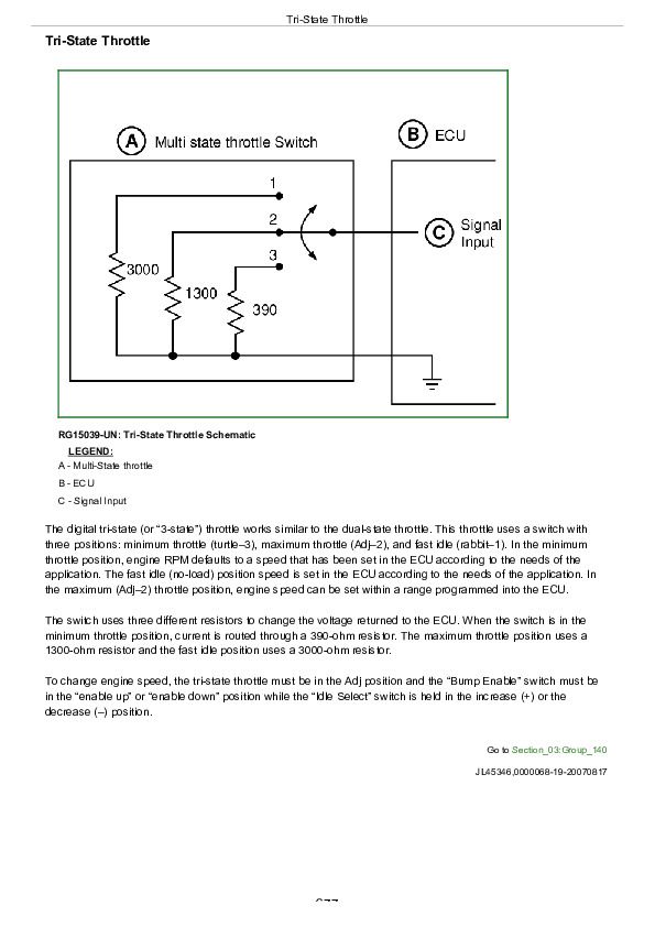
Tri-State Throttle
Water in Fuel (WIF) Sensor
Section 04: Diagnostics
Group 150: Observable Diagnostics
About This Group of the Manual
Abnormal Engine Noise
Coolant in Oil or Oil in Coolant
ECU Does Not Communicate with Service ADVISOR
ECU Does Not Communicate with Diagnostic Gauge or Gauge Displays CAN Bus Error
ECU Does Not Program with Service ADVISOR
Engine Cranks But Will Not Start
Engine Does Not Develop Full Power
Engine Emits Excessive White Exhaust Smoke
Engine Emits Excessive Black or Gray Exhaust Smoke
Engine Misfires or Runs Irregularly
Engine Oil Consumption
Check for Excessive Engine Crankcase Pressure (Blow-By) (Base Pressure)
Engine Oil Pressure Low
Engine Overheating
Engine Will Not Crank
Fuel in Oil
Guideline for Acceptable Oil Consumption
Head Gasket Failures — Check
Primary Analog Throttle Does Not Respond
Secondary Analog Throttle Does Not Respond
Group 155: Checks, Tests and Procedures
Air in Fuel — Check
Air Intake System — Check
Charge Air System — Test
Coolant System — Bleeding
Cooling System and Radiator Cap — Pressure Test
Cooling System — Test
Crankcase Pressure Blow-By Test
Cranking Speed Test
Engine Oil Pressure Check
Excessive Fuel Consumption
Exhaust System — Check
Fuel Shutoff Solenoid Test
Fuel Return Line (Leak-off) — Restriction Check
Fuel Supply Quality Check
Fuel System Bleeding
Glow Plug Check
Head Gasket — Leak Check
Intake Manifold — Pressure Measurement
Low Pressure Fuel System — Check
Mechanical Compression Test
Restarting Engine that has Ran Out of Fuel
Thermostat Operation Test
Turbocharger Oil Seal — Leak Check
Wastegate Turbocharger Test
Dynamometer Test
Group 160: Diagnostic Instructions and Information
Control Unit Information and Overview Test
Connecting to Service ADVISOR
Cylinder Cutout Test Instructions
Cylinder Electronic Compression Test Instructions
Cylinder Misfire Test
Cylinder Misfire Test Instructions
Data Parameters Descriptions As Used in Service ADVISOR
Diagnostic Gauge Active DTC Viewing Instructions
Diagnostic Gauge Data Parameters Viewing Instructions
Diagnostic Gauge Stored DTC Clearing Instructions
Diagnostic Gauge Stored DTC Viewing Instructions
Diagnostic Trouble Code Designations
Diagnostic Trouble Code (DTC) Group Locator
Electronic Unit Pump Calibration File Downloading Instructions
Electronic Unit Pump Calibration Information
Engine Control Unit (ECU) — Donating this Engine’s ECU to be Used Elsewhere
Engine Control Unit (ECU) — Replacing Current ECU with Another ECU
Engine Control Unit (ECU) — Replacing Current ECU with Another ECU — Cannot Communicate with Current ECU
Engine Control Unit (ECU) — Reprogramming Current ECU
Engine Hours — Updating Instructions
Guideline for Acceptable Oil Consumption
Harness Diagnostic Mode Test
Interactive Tests and Calibration Results — Printing, Exporting, or Saving Instructions
Intermittent DTC Diagnostics
Internal Data Monitor — Instructions
Payload File Downloading Instructions
Snapshot Instructions
Terminal Test
Trim Options Information
Group 161: Engine Position Diagnostics
000636.02 - Camshaft Position Signal Invalid
000636.05 - Camshaft Position Circuit has High Resistance
000636.06 - Camshaft Position Circuit has Low Resistance
000636.08 - Camshaft Position Signal Missing
000636.10 - Camshaft Position Signal Rate of Change Abnormal
000637.02 - Crankshaft Position Signal Invalid
000637.05 - Crankshaft Position Circuit has High Resistance
000637.06 - Crankshaft Position Circuit has Low Resistance
000637.07 - Crankshaft Position and Camshaft Position Signals Out of Sync
000637.08 - Crankshaft Position Signal Missing
000637.10 - Crankshaft Position Signal Rate of Change Abnormal
Group 162: Air System Diagnostics
000105.00 - Intake Manifold Air Temperature Signal Extremely High
000105.03 - Intake Manifold Air Temperature Signal Out of Range High
000105.04 - Intake Manifold Air Temperature Signal Out of Range Low
000105.15 - Intake Manifold Air Temperature Signal Slightly High
000105.16 - Intake Manifold Air Temperature Signal Moderately High
000676.03 - Glow Plug Relay Output Signal Received When Not Expected
000676.05 - Glow Plug Relay Output Signal Not Received
Group 163: Lubrication and Cooling Systems Diagnostics
000100.01 - Engine Oil Pressure Signal Extremely Low
000100.04 - Engine Oil Pressure Signal Out of Range Low
000100.18 - Engine Oil Pressure Signal Moderately Low
000100.31 - Engine Oil Pressure is not Zero with Engine Stopped
000110.00 - Engine Coolant Temperature Signal Extremely High
000110.03 - Engine Coolant Temperature Signal Out of Range High
000110.04 - Engine Coolant Temperature Signal Out of Range Low
000110.15 - Engine Coolant Temperature Signal Slightly High
000110.16 - Engine Coolant Temperature Signal Moderately High
Group 164: Fuel System Diagnostics
000094.03 - Low Pressure Fuel Signal Out of Range High
000094.04 - Low Pressure Fuel Signal Out of Range Low
000094.17 - Low-Pressure Fuel Signal Slightly Low
000094.18 - Low Pressure Fuel Signal Moderately Low
000097.03 - Water In Fuel Signal Out of Range High
000097.04 - Water In Fuel Signal Out of Range Low
000097.16 - Water In Fuel Detected
000174.03 - Fuel Temperature Signal Out of Range High
000174.04 - Fuel Temperature Signal Out of Range Low
000611.03 - Electronic Unit Pump Circuit Shorted to Voltage Source
000611.04 - Electronic Unit Pump Circuit Shorted to Ground
003597.01 - All Electronic Unit Pump Circuits Have High Resistance
000651.05 - Electronic Unit Pump #1 Circuit Has High Resistance
000651.06 - Electronic Unit Pump #1 Circuit Has Low Resistance
000651.13 - Electronic Unit Pump #1 Calibration Fault
000652.05 - Electronic Unit Pump #2 Circuit Has High Resistance
000652.06 - Electronic Unit Pump #2 Circuit Has Low Resistance
000652.13 - Electronic Unit Pump #2 Calibration Fault
000653.05 - Electronic Unit Pump #3 Circuit Has High Resistance
000653.06 - Electronic Unit Pump #3 Circuit Has Low Resistance
000653.13 - Electronic Unit Pump #3 Calibration Fault
000654.05 - Electronic Unit Pump #4 Circuit Has High Resistance
000654.06 - Electronic Unit Pump #4 Circuit Has Low Resistance
000654.13 - Electronic Unit Pump #4 Calibration Fault
000655.05 - Electronic Unit Pump #5 Circuit Has High Resistance
000655.06 - Electronic Unit Pump #5 Circuit Has Low Resistance
000655.13 - Electronic Unit Pump #5 Calibration Fault
Group 165: Engine Control Unit (ECU) and Throttle Diagnostics
000028.03 - Digital Throttle Signal Out of Range High
000028.04 - Digital Throttle Signal Out of Range Low
000029.03 - Throttle #2 Signal Out of Range High
000029.04 - Throttle #2 Signal Out of Range Low
000091.03 - Throttle #1 Signal Out of Range High
000091.04 - Throttle #1 Signal Out of Range Low
000091.07 - Throttle #1 Not Responding
000108.02 - Barometric Pressure Signal Invalid
000158.17 - ECU Power Down Error
000189.00 - Engine Speed Derate Condition Exists
000627.18 - Battery Voltage Moderately Low
000629.12 - ECU EEPROM Error
000629.13 - ECU Boot Block Error
001136.00 - ECU Temperature Signal Extremely High
001136.16 - ECU Temperature Signal Moderately High
001569.31 - Engine in Derate Condition
003509.03 - Sensor Supply #1 Voltage Out of Range High
003509.04 - Sensor Supply #1 Voltage Out of Range Low
003510.03 - Sensor Supply #2 Voltage Out of Range High
003510.04 - Sensor Supply #2 Voltage Out of Range Low
003597.18 - Battery Voltage Moderately Low
Group 166: Application Diagnostics
000091.13 - Throttle #1 Out of Calibration
000107.31 - Air Filter Restriction Detected
000111.01 - Engine Coolant Level Low
000569.03 - Rear Axle Differential Lock Signal Out of Range High
000569.04 - Rear Axle Differential Lock Signal Out of Range Low
000970.31 - External Engine Shutdown Switch Active
000971.31 - External Fuel Derate Switch Active
002003.09 - No CAN Message Received From Source Address 17 Within Time Out Period
002023.09 - The ETCP1 Message From ICC Has Not Been Received
003597.01 - Injector Power Supply Voltage Extremely Low
003597.18 - Injector Power Supply Voltage Moderately Low
524037.02 - MFWD Switch Circuit Fault
524223.03 - Rear Axle Differential Lock Circuit Fault
524225.31 - Engine Start Protection Bypass Detected
524235.03 - MFWD Solenoid Circuit Voltage High
524235.04 - MFWD Solenoid Circuit Voltage Low
Section 05: Tools and Other Materials
Group 170: Tools
DFRG9
313793
D01003AA
D01109AA
D01110AA
D01168AA
D01200AA
D01218AA
D05012ST-A
D05058ST
D05104ST
D05223ST
D17024BR
D17525CI
D17526CI
D17527CI
FKM10002
JDE38-2
JDE38-3
JDE81-4
JDE135
JDE138
JDE147
JDE645E
JDF13B
JDG22
JDG23
JDG193
JDG451
JDG698A
JDG719
JDG782A
JDG968
JDG1571
JDG1658
JDG1660
JDG1676
JDG1678
JDG1679
JDG1687
JDG1690
JDG1691
JDG1694
JDG1697
JDG1700
JDG1700P6
JDG1702
JDG1703
JDG1704
JDG1721
JDG1755
JDG1791
JDG1822
JDG1854
JDG2073
JDG10038
JDG10221
JDG10245
JDG10409
JDG10466
JT01674A
JT01718
JT01720
JT01724
JT05470
JT05697A
JT05893
JT05949
JT05993
JT07254
JT07306
JT25510
JT30040B
JT30041A
Group 180: Lubricants, Sealants, Cleaners
DT4052 — Petroleum Grease
DT5446 — Permabond MM115
DT5189 — Loctite #380-50, 1oz bottle
LOCTITE® 242 — Thread Lock and Sealer
LOCTITE® 277 — Adhesive & Sealant
LOCTITE® 592 — Adhesive
LOCTITE® 7649 — Clean and Cure Primer
LOCTITE® 5910 — Silicone Sealant
LOCTITE® 5127 — Silicone Sealant
LOCTITE® 609 — Adhesive
LOCTITE® 222 — Adhesive (purple)
Section 06: Specifications and Wiring Drawings
Group 200: Repair and General OEM Specifications
Unified Inch Bolt and Screw Torque Values
Metric Bolt and Screw Torque Values
Engine Rebuild Specifications
Cylinder Head and Valves Specifications
Cylinder Block, Liners, Pistons, and Rods Specifications
Crankshaft, Main Bearings, and Flywheel Specifications
Camshaft, Balancer Shafts and Timing Gear Train Specifications
Lubrication System Specifications
Cooling System Specifications
Fuel System Specifications
Air Intake and Exhaust System Specifications
Starting and Charging Systems Specifications
Electronic Engine Control Repair and Adjustment Specifications
Group 205: Diagnostic Specifications
Turbocharger Boost Table
Engine Power Rating and Speed Specifications
Coolant Temperature Sensor Characteristic Graph
Fuel Temperature Sensor Characteristic Graph
Manifold Air Temperature Sensor Characteristics
OEM Engines Derate Specifications
Glow Plug Specifications
Group 210: Wiring Diagrams
2.4L ECU Wiring Diagram 1
3.0L ECU Wiring Diagram 2
2.4L-3.0L ECU Wiring Diagram 3
2.4L/3.0L ECU Wiring Diagram 4
2.4L-3.0L ECU Wiring Diagram 5
2.4L-3.0L ECU Wiring Diagram 6
2.4L-3.0L ECU Wiring Diagram 7
OEM Engine-Instrument Panel Components Wiring Diagram
OEM Engine-Instruments Panel/Engine Start Components Wiring Diagram (Cont)
John Deere PowerTech E 2.4L and 3.0L Diesel Engines Component Technical Manual (CTM101019)


