John Deere Compact Loaders 244J, 304J Operation and Test Service Manual (TM2206)
Catalog:
Model:
Complete Diagnosis and Test manual with Electrical Wiring Diagrams for John Deere Compact Loaders 244J (SN.-23289), 304J (SN.-23371), with all the technical information to maintain, diagnose, and test the loader like professional mechanics.
John Deere Compact Loaders 244J, 304J workshop Diagnostics and Test manual includes:
* Numbered table of contents easy to use so that you can find the information you need fast.
* Detailed sub-steps expand on Operation and Test procedure information
* Numbered instructions guide you through every Operation and Test procedure step by step.
* Troubleshooting and electrical service procedures are combined with detailed wiring diagrams for ease of use.
* Notes, cautions and warnings throughout each chapter pinpoint critical information.
* Bold figure number help you quickly match illustrations with instructions.
* Detailed illustrations, drawings and photos guide you through every procedure.
* Enlarged inset helps you identify and examine parts in detail.
TM2206 - John Deere 244J (SN.-23289) , 304J (SN.-23371) Compact Loaders Technical Manual - Operation and Test.pdf
tm10204 - John Deere 244J (—23289) et 304J (—23371)Chargeuses à roues.pdf
Total Pages: 514 pages
File Format: PDF (bookmarked, ToC, Searchable, Printable)
Category: Operation and Test
Language: English French
Published on 2020/01/25
MAIN SECTIONS
Foreword
Technical Information Feedback Form
General Information
Safety Information
Operational Checkout Procedure
Operational Checkout Procedure
Engine
Theory of Operation
Diagnostic Information
Adjustments
Tests
Electrical System
System Information
System Diagrams
Sub-System Diagnostics
References
Tests and Adjustments
Power Train
Theory Of Operation
Diagnostic Information
Adjustments
Tests
Hydraulic System
Theory of Operation
Diagnostic Information
Adjustments
Test
Heating and Air Conditioning
Theory of Operation
Diagnostic Information
Tests
Table of Contents
Foreword
Technical Information Feedback Form
Section 9000: General Information
Group 01: Safety Information
Recognize Safety Information
Follow Safety Instructions
Operate Only If Qualified
Wear Protective Equipment
Avoid Unauthorized Machine Modifications
Add Cab Guarding For Special Uses
Inspect Machine
Stay Clear of Moving Parts
Avoid High-Pressure Oils
Beware of Exhaust Fumes
Prevent Fires
Prevent Battery Explosions
Handle Chemical Products Safely
Dispose of Waste Properly
Prepare for Emergencies
Use Steps and Handholds Correctly
Start Only From Operator's Seat
Use and Maintain Seat Belt
Prevent Unintended Machine Movement
Avoid Work Site Hazards
Use Special Care When Operating Loader
Keep Riders Off Machine
Avoid Backover Accidents
Avoid Machine Tip Over
Operating on Slopes
Operating or Traveling On Public Roads
Inspect and Maintain ROPS
Add and Operate Attachments Safely
Park and Prepare For Service Safely
Service Cooling System Safely
Remove Paint Before Welding or Heating
Make Welding Repairs Safely
Drive Metal Pins Safely
Section 9005: Operational Checkout Procedure
Group 10: Operational Checkout Procedure
Operational Checkout
Section 9010: Engine
Group 05: Theory of Operation
POWERTECH 2.4 L (4024) and 3.0 L (5030) John Deere Engines
Group 15: Diagnostic Information
Diagnose Observable Engine Symptoms
Group 20: Adjustments
Engine Speed Test and Adjustment
Group 25: Tests
JT05800 Digital Thermometer Installation
Intake Manifold Pressure Test—Turbocharger Boost
Section 9015: Electrical System
Group 05: System Information
Electrical Diagram Information
Component Identification Table
Fuse (Blade-Type) Color Codes
Group 10: System Diagrams
Fuse and Relay Specifications
System Functional Schematic, Wiring Diagrams, and Component Locations Master Legend
System Functional Schematic and Section Legend
Batteries and Power Cables (W5) Component Location
Loader/Rear Frame Harness (W6) Component Location
Loader/Rear Frame Harness (W6) Wiring Diagram
Cab Main Harness (W7) Component Location
Cab Main Harness (W7) Wiring Diagram
Cab Roof Harness (W8) Component Location
Cab Roof Harness (W8) Wiring Diagram
Rear Lights Harness (W9) Component Location
Rear Lights Harness (W9) Wiring Diagram
AC Thermostat/Blower Harness (W10) Component Location
AC Thermostat/Blower Harness (W10) Wiring Diagram
Air Conditioning Harness (W11) Component Location
Air Conditioning Harness (W11) Wiring Diagram
Fourth Function Harness (W12) Component Location—Optional
Fourth Function Harness (W12) Wiring Diagram—Optional
Ride Control Harness (W13) Component Location
Ride Control Harness (W13) Wiring Diagram
Group 15: Sub-System Diagnostics
Power Circuit Theory of Operation
Start Circuit Theory of Operation
Preheat Circuit Theory of Operation
Charging and Start Release Circuits Theory of Operation
Forward, Reverse, and Back-Up Alarm Circuits Theory of Operation
Park Brake Release Circuit Theory of Operation
Differential Lock Circuit Theory of Operation
Cooling Fan Drive Circuit Theory of Operation
Chassis Control Unit and Input/Output Circuits Theory of Operation
Group 20: References
POWERTECH 2.4 L (4024) and 3.0 L (5030) John Deere Engines
Diagnostic Trouble Codes Quick Reference List
Diagnostic Trouble Code Diagnostics
Electrical Component Specifications
Monitor Display Remove and Install
Chassis Control Unit Remove and Install
Ground Speed Sensor Install—244J (S.N. 11007—23289) and 304J (S.N. 11007—23371)
Controller Payload Download
Controller Payload Update
Chassis Control Unit (CCU) Configuration Test
Replace DEUTSCH DEUTSCH is a trademark of the Deutsch Co. Connectors
Replace DEUTSCH DEUTSCH is a trademark of Deutsch Co. Rectangular or Triangular Connectors
Install DEUTSCH DEUTSCH is a trademark of Deutsch Co. Contact
Replace CINCH CINCH is a trademark of the Cinch Co. Connectors
Install CINCH CINCH is a trademark of the Cinch Co. Contact
Replace Small MATE-N-LOK MATE-N-LOK is a trademark of AMP Inc. Socket Connector
Replace Small MATE-N-LOK MATE-N-LOK is a trademark of AMP Inc. Pin Connector
Remove Connector Body from Blade Terminals
Group 25: Tests and Adjustments
Accelerator Pedal Adjustment
Alternator Test
Ground Speed Sensor Adjustment—244J (S.N. —23189) and 304J (S.N. —23371)
Return-to-Dig Adjustment
Section 9020: Power Train
Group 05: Theory Of Operation
Power Train Description
Hydrostatic Transmission Operation—Neutral
Hydrostatic Transmission Operation—Forward (Low Speed)
Hydrostatic Transmission Operation—Forward (High Speed)
Hydrostatic Transmission Operation—Reverse (Low Speed)
Hydrostatic Pump Operation
Hydrostatic Pump Swash Plate Operation
Hydrostatic Pump Control Operation—Reverse (Engine Speed at Less than Fast Idle)
Hydrostatic Pump Control Operation—Forward (Engine Speed at Fast Idle)
High Pressure Relief Valve Operation
Hydrostatic Motor Operation—Neutral
Hydrostatic Motor Operation—Reverse (Low Speed)
Hydrostatic Motor Operation—Forward (High Speed)
Inching Valve Operation
Brake Valve Operation
Service and Park Brake Description
Park Brake Release Solenoid Valve Operation
Park Brake Operation—244J
Service Brakes Operation—244J
Differential Lock Operation—244J
Park Brake, Service Brake, and Differential Lock Operation—304J
Cooling Fan Pump and Motor Circuit Operation
Group 15: Diagnostic Information
Diagnose Hydrostatic Transmission Malfunctions
Diagnose Differential and Axle Malfunctions
Diagnose Driveline Malfunctions
Diagnose Park Brake Malfunctions
Diagnose Service Brake Malfunctions
Diagnose Hydraulic Cooling Fan Malfunctions
Hydraulic Circuit Symbols
Power Train Component Location
Service and Park Brake System Component Location
Hydrostatic Transmission Schematic
Service and Park Brake System Schematic
Group 20: Adjustments
Hydrostatic Pump Servo Piston Neutral Adjustment
Hydrostatic Motor Minimum Displacement Adjustment
Brake/Inching Pedal Linkage Adjustment
Group 25: Tests
Before Performing Hydrostatic Transmission Tests
Neutral Charge Relief Valve Pressure Test and Adjustment
Hydrostatic Pump Begin Regulation Test and Adjustment
Hydrostatic Pump Performance (Timing) Test and Adjustment
High Pressure Relief Valve Test and Adjustment
Hydrostatic Pump Pressure Override (POR) Valve Pressure Test and Adjustment
Hydrostatic Motor Begin Regulation of Displacement Control Valve Test and Adjustment
Hydrostatic Pump Isolation Procedure
Directional Control Valve Spool Leakage Test
Hydrostatic Adjusting Screws (With Tamper-Proof Caps)
Park Brake Release Pressure Test
Cooling Fan Motor RPM Test
Cooling Fan System Pressure and Pump Flow Test
Hydraulic Oil Clean-Up Procedure Using Portable Filter Caddy
Section 9025: Hydraulic System
Group 05: Theory of Operation
Main Hydraulic System Operation
Main Hydraulic Pump Operation
Priority Valve Operation
Steering Circuit Operation
Steering Valve Operation
Steering Cylinder Relief Valve Operation
Loader Control Valve Operation
Loader Circuit Relief Valve Operation
Ride Control Valve Operation
Pilot Control Valve Operation
Pilot Lockout Solenoid Valve Operation
Group 15: Diagnostic Information
Diagnose Hydraulic System Malfunctions
Hydraulic Circuit Symbols
Loader System Component Location
Steering System Component Location
Loader System Schematic
Steering System Schematic
Group 20: Adjustments
Steering Alignment Adjustment
Ride Control Accumulator Check and Charge Procedure
Group 25: Test
Hydraulic Oil Cleanup Procedure Using Portable Filter Caddy
Hydraulic Oil Warm-Up Procedure
Main Hydraulic Pump Flow Test
Steering System Relief Pressure Test
Steering Valve Leakage Test
Steering Cylinder Leakage Test
Loader System Relief Valve Pressure Test
Loader Circuit Relief Valve Pressure Test
Ride Control System Relief Valve Pressure Test
Loader Cylinder Drift Test
Boom and Bucket Cylinder Leakage Test
Pilot Control Valve Pressure Test
Section 9031: Heating and Air Conditioning
Group 05: Theory of Operation
Air Conditioning System Cycle of Operation
Group 15: Diagnostic Information
Diagnose Air Conditioning System Malfunctions
Diagnose Heater System Malfunctions
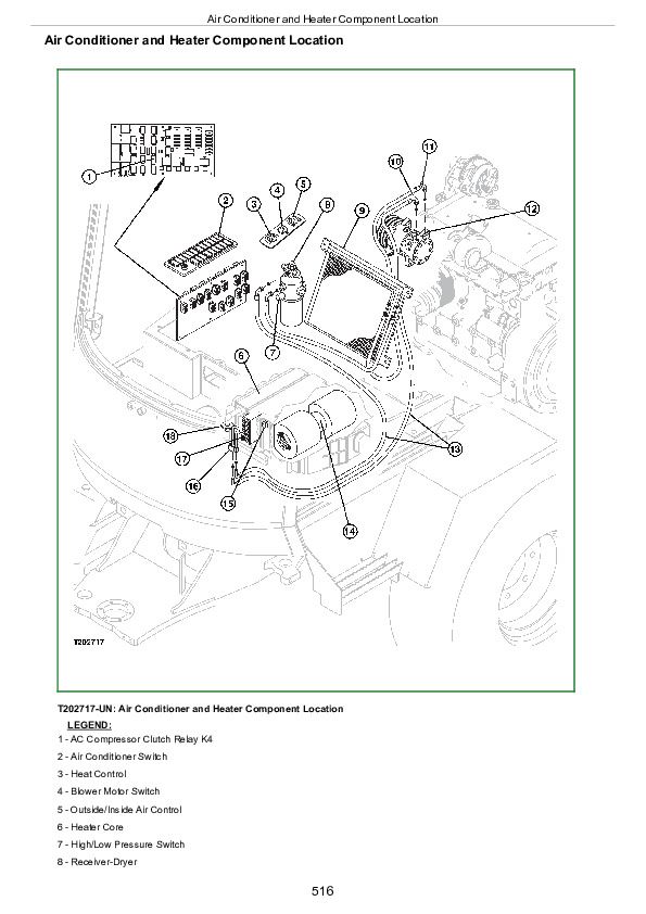
Air Conditioner and Heater Component Location
Group 25: Tests
Refrigerant Cautions and Proper Handling
Air Conditioner and Heater Operational Checks
Refrigerant Leak Test
Air Conditioner Compressor Clutch Test
Air Conditioner High/Low Pressure Switch Test
AC Thermostat Switch Test
R134a Air Conditioning System Test
Operating Pressure Diagnostic Chart
John Deere Compact Loaders 244J, 304J Operation and Test Service Manual (TM2206)


